
Saying More in Multiline Text
When you just can't shoehorn your creative genius into one or more one-line pieces of text, AutoCAD's multiline text object gives you room to go on and on and on. The following procedure shows you how to create multiline text with the MTEXT command.
Making it with Mtext
 The first part of the MTEXT command prompts you for various points and options. The order is a bit confusing, so read these steps and the prompts carefully.
Here's how you use the MTEXT command:
- Set an appropriate text style current and (optionally) turn off running object snaps, as described in Steps 1 and 2 in the “Using the Same Old Line” section, earlier in this chapter.
If you're doing real drafting, you should also set an appropriate layer current.
 On the Home tab's Annotation panel, click the upper part of the split button labeled Text to start the MTEXT command.
The command line displays the current text style and height settings, and prompts you to select the first corner of an imaginary rectangle that will determine the word-wrapping width for the text object:
Current text style: “Standard” Text height: 0.2000 Annotative: No Specify first corner:- Pick a point in the drawing.
The command line prompts you for the opposite corner of a rectangle that will determine the word-wrapping width; it also gives you the option of changing settings first:
Specify opposite corner or [Height/Justify/Line spacing/ Rotation/Style/Width/Columns]: - Type H and press Enter to change the default text height.
The command line prompts you for a new default text height:
Specify height <0.2000>:
- Type an appropriate text height.
See the “Taking your text to new heights” section, earlier in this chapter, for information. If you're adding text in model space, I highly recommend that you use annotative text.
The prompt for the opposite corner of the Mtext rectangle reappears. The command line shows
Specify opposite corner or [Height/Justify/Line spacing/ Rotation/Style/Width/Columns]: - If you want a different justification from the default (top left), type J, press Enter, and choose one of the other justification options.
Enter justify multiline text in the search box of the online help system if you want an explanation of the other justification options.
- Pick another point in the drawing.
 Don't worry about the height of the rectangle that you create by choosing the second point; the width of the rectangle is all that matters. AutoCAD adjusts the height of the text rectangle to accommodate the number of lines of word-wrapped text. Don't worry too much about the width, either; you can adjust it later.
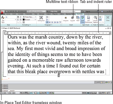
The In-Place Text Editor frameless window appears with the tab and indent ruler above it, and a previously hidden Text Editor contextual tab appears on the Ribbon, as shown in Figure 13-4. (If you don't see the tab and indent ruler at the top of your Text Editor window, right-click inside the window and choose Editor Settings, then Show Ruler from the right-click menu.)
New isn't always better; you may prefer the classic Text Formatting toolbar over the Ribbon's Text Editor contextual tab. If you want to give the classic version a test drive, change the value of the system variable MTEXTTOOLBAR. The default value (2) displays the Text Editor tab only; setting it to 1 displays both the tab and the toolbar. I don't recommend setting this variable to 0 — that turns off the Text Formatting toolbar in all workspaces. For more about system variables, see Chapter 26. When you create multiline text in either AutoCAD or AutoCAD LT, your text objects default to Dynamic Column mode. You can tell that's what you're going to get if the In-Place Text Editor displays a double-headed-arrow symbol in the center of the bottom border of the rectangle you define (refer to Figure 13-4). This is a useful default if you really are writing a novel, but for most drawing notations, I recommend you turn off columns. To do so, click Columns on the Text Editor panel (or the Text Editing toolbar if that's your preference) and choose No Columns. Setting the system variable MTEXTCOLUMN to 0 will force the MTEXT command to create non-columnized text. - Verify the text font and height.
The text font and height should be right if you correctly performed Steps 1, 4, and 5. If not, you can change these settings in the Font drop-down list and the Text Height text box on the Text Editor tab (or the classic Text Formatting toolbar).
- Type text into the text area of the In-Place Text Editor.
AutoCAD word-wraps multiline text automatically. If you want to force a line break at a particular location, press Enter.
- If you want other formatting options, select text, right-click, and make an appropriate choice from the menu (as shown in Figure 13-5).
By convention in most industries, text in drawings is always uppercase. How many times have you forgotten to press the Caps Lock key before entering drawing text? How many times have you forgotten to turn Caps Lock off again when it's time to type your e-mail? To save yourself some agony, right-click in the In-Place Text Editor and choose AutoCAPS from the menu.
- Click Close Text Editor (or OK in the classic Text Formatting toolbar).
The In-Place Text Editor window closes, and AutoCAD adds your text to the drawing.
You can close the text editor much more easily by simply clicking outside its window. But if you like clicking buttons instead, AutoCAD has amply provided for you. - Add annotation scales to the new multiline text object.
The steps are the same for multiline text as for single-line text. Refer to the “Turning On Your Annotative Objects” section, earlier in this chapter, if you need a refresher.

Figure 13-5: Right-click your way to textual excellence.
As you can tell by looking at the Text Editor tab (or the Text Formatting toolbar) and multiline text right-click menu, the MTEXT command gives you plenty of other options. You can show or hide the toolbar, the ruler, or the Options buttons, and you can give the In-Place Text Editor an opaque background. Other tool buttons give you access to columns and numbered or bulleted lists (both are covered in the section “Doing a number on your Mtext lists,” later in this chapter).
Between them, the Text Editor tab (or the Text Formatting toolbar) and the right-click menu also include a Stack/Unstack feature for fractions, a Find and Replace utility, tools for changing between lowercase and uppercase, options for applying background masks and inserting fields, a special Symbol submenu, and an Import Text option for importing text from a TXT (ASCII text) file or RTF (Rich Text Format) file. I discuss background masks and fields in the next section. If you think you may have a use for any of these other features, choose Command Reference![]() Commands
Commands![]() M Commands
M Commands![]() MTEXT in AutoCAD's online help browser to find out more about them.
MTEXT in AutoCAD's online help browser to find out more about them.
It slices, it dices …
Two more useful options on the multiline text right-click menu are Background Mask and Insert Field.
Mtext dons a mask
When you turn on background masking, AutoCAD hides the portions of any objects that lie underneath the multiline text. Use these steps to turn on and control this feature:
- Right-click in the In-Place Text Editor and choose Background Mask from the menu.
The Background Mask dialog box appears.
- Click the Use Background Mask check box so that this option is turned on.
- Either click Use Drawing Background Color (to make the mask the same color as the drawing area's background color) or choose a color from the drop-down list (to make the text appear in a solid rectangle of the specified color).
- Click OK to return to the In-Place Text Editor.
 One of the most irritating features of the Use Background Mask dialog box was its constant belief that you always wanted a fixed-size boundary around the mask, and — even worse — that it should be red (99% of the time, people want the background mask to be the same color as . . . er, the background.) Use Background Mask is now smart enough to remember the last boundary distance, and — even better — that you really do want the background color for the mask to be Background.
If you've turned on background masking but it isn't having the desired effect, use the TEXTTOFRONT command to move the text on top of other objects. Click the Bring to Front drop-down button on the Home tab's Modify panel slideout and choose Bring Text to Front.
Mtext plays the field
The Insert Field option on the In-Line Text Editor's right-click menu creates a text field that updates automatically every time you open, save, plot, or regenerate the drawing. Fields can contain data such as the date, filename, or author. Fields draw information from the operating-system settings, Drawing Properties dialog box, sheet sets feature (not covered in this book), and AutoCAD system variables. (For more information about system variables, see Chapter 26.) Use the following procedure to add a field while you're creating multiline text:
- Right-click in the In-Place Text Editor and choose Insert Field from the menu.
The Field dialog box appears.
- Choose a Field Name in the left column.
- Choose a Format in the right column, or for date fields, type a format in the Date Format box.
- Click OK.
AutoCAD adds the field to the Mtext object that you're creating or editing.
Doing a number on your Mtext lists
Mtext supports bulleted and numbered lists. This feature is especially useful for creating general drawing notes, as shown in Figure 13-6. AutoCAD automates the process of creating numbered lists almost completely. Here's how:
- Follow Steps 1 through 8 in the earlier section, “Making it with Mtext,” to open the In-Place Text Editor.
- Type a title — for example, DESIGN CRITERIA.
If you want your title underlined, click Underline on the Formatting panel (or the Text Formatting toolbar) before you type the title; click Underline again to turn it off. Press Enter to go to the next line and press Enter again to leave a little more space.
- On the Paragraph panel of the Text Editor tab, click the Bullets and Numbering drop-down button; verify that Allow Auto-List, Use Tab Delimiter Only, and Allow Bullets and Lists are selected; and then click Numbered, as shown in Figure 13-6.
The number 1 followed by a period appears on the current line, and the cursor jumps to the tab stop visible in the ruler at the top of the In-Place Text Editor window.
 Enabling Numbered places numerals followed by periods in front of items in a list. (Bulleted places bullet characters in front of items in a list.) Auto-List enables automatic numbering — each time you press Enter to move to a new line, AutoCAD increments the number.
Figure 13-6: Tabs, indents, and automatic numbering set to create numbered lists.
- Type the text corresponding to the current number or bullet.
As AutoCAD wraps the text, the second and subsequent lines align with the tab stop, and the text is indented automatically.
- Press Enter at the end of the paragraph to move to the next line.
Just like creating numbered lists in your favorite word processor, AutoCAD automatically inserts the next number at the beginning of the new paragraph, with everything perfectly aligned.
To create nested numbered or bulleted items as shown in Figure 13-6, simply press Tab at the start of the line. If you change your mind, you can bump a nested text item up a level by selecting the item in the In-Place Text Editor and pressing Shift+Tab. - Repeat Steps 4 and 5 for each subsequent numbered or bulleted item.
For legibility, you sometimes want to add spaces between the notes. If you press Enter twice to give yourself a blank line, AutoCAD — like every good word processor — thinks you're finished with your list and turns numbering off. AutoCAD is smart, so you need to be smarter. If you put the cursor at the end of the first note and press Enter, you get a blank line. The problem is, the blank line is now numbered, and your intended Note 2 is now Note 3. Just press the Backspace key. The number on the blank line disappears, and Note 2 is back to being Note 2 again. When you delete a numbered item, the remaining numbers adjust automatically.
If you don't like the horizontal spacing of the numbers or the alignment of subsequent lines, you can adjust them easily by manipulating the tab and indent markers in the In-Place Text Editor's ruler.
- In the ruler, drag the upper slider (the triangle pointing down) to the right a short distance. Drag the lower slider (the triangle pointing up) a slightly greater distance to the right.
The upper slider controls the indentation of the first line in each paragraph. The lower slider controls the indentation of the second and subsequent lines. An indent of one to two of the short, vertical tick marks usually works well for the first line. An indent of two to four tick marks works well for the second and subsequent lines.
- Click in the ruler just above the lower slider.
A small L appears above the lower slider. The L shows the tab stop.
Make sure that the corner of the L aligns horizontally with the point of the lower slider triangle. If not, click and drag the L until it aligns.
If you prefer to type tab and indent distances, not adjust them with the cursor, open the Paragraph dialog box by either
- Clicking the little arrow at the right end of the Paragraph panel label (in AutoCADese, it's called a Panel Dialog Box Launcher).
- Right-clicking inside the In-Place Text Editor and choosing Paragraph.
Whichever way you do it, if you select text first, the tab and indent changes apply to the selected text. If you don't select text first, the changes apply to new text from that point in the multiline text object forward.
Line up in columns — Now!
AutoCAD is getting more and more word processor–like. A few releases back, it was simple indents, then came numbered and bulleted lists. The most recent addition is columns in multiline text.
Columns come in two flavors: static and dynamic.
- Static: You specify the number of columns into which you want to flow your text. Columns are always the same height, and text is allowed to overflow the final column if there's too much of it.
- Dynamic: As you might expect, these columns are friendlier, more flexible, and the life of any party. You can individually adjust column heights, and new columns are added automatically to accommodate the text.
Selecting either column type also offers you a Column Settings dialog box where you can specify values numerically instead of by dragging grips.
Figure 13-7 shows a block of multiline text imported as an RTF file from a word processor and then formatted in dynamic columns with the Manual Height option.
Setting up columns is pretty straightforward — the following steps explain how:
- Open a drawing that contains a large multiline text object or create a large multiline text object in a new drawing.
If you already have drawing specifications or general notes in a word processor document, or even a text file, you can right-click inside the MTEXT command's In-Place Text Editor and choose Import Text. The Select File dialog box opens, giving you the choice of Rich Text Format (RTF) or ASCII text (TXT) files.
- If the In-Place Text Editor is not already open, double-click the text, or select it, then right-click and choose Mtext Edit.

- Click Columns in the Insert panel and choose either Dynamic Columns or Static Columns.
If you choose Dynamic Columns, select either Auto Height or Manual Height. Selecting Manual Height puts grips on each column so you can adjust their height individually (refer to Figure 13-7). Auto Height displays a single grip, so the heights of all columns remain the same, but new columns are still added as required by the amount of text.
If you choose Static Columns, select the number of columns you want from the menu. Clicking 2, for example, creates two columns regardless of the length of your text — you may end up with overflowing text or empty columns.
- Click Close Text Editor (or OK in the Text Formatting toolbar) when you're satisfied with the column arrangement.
You can revert to a non-columnar arrangement by clicking the Columns button in the Insert panel and choosing No Columns.
Modifying Mtext
After you create a multiline text object, you can edit it in the same ways as a single-line text object: Select the object, right-click, and choose Mtext Edit or Properties.
- Mtext Edit: Selecting this option opens the In-Place Text Editor window so that you can change the text contents and formatting.
- Properties: Selecting this option opens the Properties palette, where you can change overall properties for the text object.
- Quick Properties: Enable this setting on the status bar to make simply selecting a multiline text object open the Quick Properties palette, in which you can modify a subset of the Mtext object's properties.
The easiest way to change the word-wrapping width of a paragraph text object is to grip-edit it. Select the text object, click one of the corner grips, release the mouse button, move the crosshairs, and click again. Chapter 10 describes grip editing in detail.
![]()
![]() Just like any good word processor or text editor, AutoCAD includes both a spell checker and a find-and-replace tool for text or dimensions. To check the spelling of selected objects or the entire drawing, click the Annotate tab on the Ribbon and choose Check Spelling from the Text panel to display the Check Spelling dialog box. On the same panel, clicking Find Text, or typing FIND and pressing Enter displays the Find and Replace dialog box. Handily, Find and Replace and Spell Check are both also accessible from the Text Editor tab's Spell Check and Tools panels — in case you just want to replace text or check spelling within a single multiline text object. Look up SPELL or FIND in the online help if you need more information on either command.
Just like any good word processor or text editor, AutoCAD includes both a spell checker and a find-and-replace tool for text or dimensions. To check the spelling of selected objects or the entire drawing, click the Annotate tab on the Ribbon and choose Check Spelling from the Text panel to display the Check Spelling dialog box. On the same panel, clicking Find Text, or typing FIND and pressing Enter displays the Find and Replace dialog box. Handily, Find and Replace and Spell Check are both also accessible from the Text Editor tab's Spell Check and Tools panels — in case you just want to replace text or check spelling within a single multiline text object. Look up SPELL or FIND in the online help if you need more information on either command.