
Understanding Geometric Constraints
Adding geometric constraints to object geometry may take a little getting used to because it's unlike anything AutoCAD has offered before.
In a few cases, AutoCAD's geometric constraints have equivalent object snaps. There are tangent, parallel, and perpendicular object snaps and tangent, parallel, and perpendicular geometric constraints. The difference between these relations as object snaps and geometric constraints is that constraints are persistent.
For example, you can draw a line at any angle, start another line, turn on parallel object snap, and create a second line that's parallel to the first. But then you can easily rotate either line so they're no longer parallel. If, however, you apply a parallel constraint to the second line, it will rotate with the first line, always maintaining that parallel relation until you delete the constraint.
There are 12 geometric constraints you can apply to your drawing objects, and the easiest way to apply them is by clicking buttons on the Geometric panel of the Ribbon's Parametric tab. Table 19-2 presents a list of the geometric constraints and explains what they do.
Table 19-2 Geometric Constraints


 Text objects can also be geometrically constrained. You can apply horizontal or vertical constraints to text, and you can make text parallel, perpendicular, or collinear with lines. Anyone who's had to label utility lines on civil engineering drawings in earlier releases so the text aligns with the linework (who… moi??) will be very happy with this feature!
Applying a little more constraint
If you're using the full version of AutoCAD (not AutoCAD LT), you can constrain drawing objects geometrically by clicking buttons on the Geometric panel of the Parametric tab. In the following steps, I show you how to get started with geometric constraints.
 You can find the files I use in this sequence of steps at this book's companion web site. Go to www.dummies.com/go/autocad2012 and download afd19.zip. The drawing named afd19c.dwg contains the unconstrained geometry, and drawing afd19d.dwg contains the end product.
- Start a new drawing. Make the Ribbon's Parametric tab current and turn off Snap, Ortho, Polar, Osnap, and Otrack at the status bar.
For real drafting, you probably want to use these precision aids, but for this example, you get a better sense of parametrics with a really imprecise drawing.
- Draw some linework using the PLINE command and add a couple of circles.
Draw something similar to Figure 19-10 if you want to follow closely.
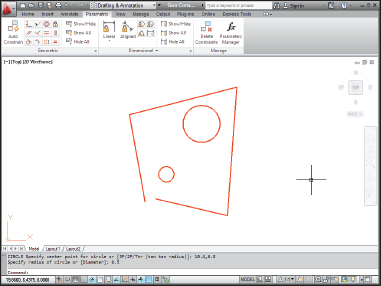
Figure 19-10: Random shapes that badly need constraining.
Every drawing is going to be tackled differently, and it's a good idea to think ahead and figure out the most efficient way to apply the constraints you need so that your design intent is maintained. In this example, I want to end up with two concentric circles in the middle of a square.
As I mention earlier, you'll find it a lot easier to apply constraints if at least one point on the geometry is fixed in space. In many cases, one of the first constraints you should think about applying is Fix, the one that constrains a point to one location in the drawing area.In this example, I'm going to lock one of the endpoints of the polyline into position.
 Click Fix in the Geometric panel and then click a point you want to fix in space.
A blue padlock icon is displayed beside the pickbox, and the red pick point marker appears when you're over a point you can constrain (see Figure 19-11). In this example, I click one of the endpoints on the polyline. A padlock icon appears in the constraint bar indicating the endpoint of the polyline segment is fixed in place.
With at least one point on the geometry fixed in place, I start constraining the geometry by closing the gap in the linework.

 Click Coincident in the Parametric tab's Geometric panel.
You use a coincident constraint to make two points coincide. A blue coincident icon appears near the pickbox and, as you move your crosshairs over an object, a marker appears over relevant points — in the case of lines or polyline segments, at the endpoints and midpoint.
Use appropriate drawing commands based on your design intent. I use a polyline in this example because the ends of the segments are already coincident-constrained by being part of a single polyline object. If I draw this shape with lines, I have to apply individual coincident constraints to each corner.- Click an endpoint on the first polyline segment you want to connect and then click an endpoint on the second segment.
The endpoint of the second polyline segment jumps to the endpoint of the first line, and a small blue square — the marker for coincident constraints — appears at the intersection. (If you don't see the little blue square, click Show All in the Geometric panel.)
Next, I apply some orthographic parameters so my linework starts to look a little more like a rectangle.
 Click Horizontal in the Parametric tab's Geometric panel and then click a line or polyline segment you want to be aligned with the drawing's X-axis.
In this example, I picked the bottom segment of the polyline. The segment realigns itself horizontally from the endpoint nearest to where you picked the line (unless a Fix constraint is added first), and a horizontal constraint marker — officially called a constraint bar — appears near the object.
 Click Vertical to align a line or polyline segment with the drawing's Y-axis.
In this example, I picked the left verticalish polyline segment. The segment realigns itself at 90 degrees to the horizontal segment, and a constraint bar showing a vertical constraint appears. With one horizontally and one vertically constrained line segment, you're halfway to a geometrically precise rectangle!
Because rectangles have parallel and perpendicular sides, next I apply those constraints to my linework.
 Click Parallel in the Parametric tab's Geometric panel, click the vertically constrained line segment, and then click the line segment opposite.
Because there's already a vertical constraint applied to one segment, it doesn't matter which line you pick first. If neither line had an existing constraint, the second line you picked would become parallel to the first line.
 Always keep your design intent in mind as you think about which constraints to apply and when to apply them. As a general rule, it's good to start with the most important and drill down to the least important. And, as I remind you earlier in the chapter, applying a fix constraint early in the game can prevent your geometry rearranging itself in ways you don't expect.
To make the final side of the almost-rectangle orthogonal with the other three, I could use another parallel constraint and click the bottom line. However, I don't want to wear out my Parallel button, so I'll use Perpendicular on the final segment.
 Click Perpendicular on the Geometric panel, click either of the vertical sides, and then click the non-orthogonal side.
Again, because three of the four sides are already constrained to horizontal and vertical, it doesn't matter which segment you pick first.
To delete a constraint, move the mouse pointer over the constraint marker to display the constraints bar (see Figure 19-12), right-click and choose Delete.From four nonorthogonal, not-even-closed line segments, applying a handful of constraints yields a perfect rectangle — but I really want a square! Here's where the Equal constraint comes in.
 Click Equal on the Geometric panel, click the bottom side, and then click either of the vertical sides.
A perfect square! Now I want to constrain those circles.
My design intent in this example is to have the circles be concentric and to locate their centers in the exact center of the rectangle. First the easy part: Making the circles concentric.
 Click Concentric in the Geometric panel, click one circle, and then click the other.
The two circles are concentrically constrained (try saying that ten times in a hurry!), and a new constraint bar appears in their vicinity. Try moving one circle by clicking it and watch the other tag along.
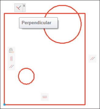
Figure 19-12: Constraining to orthogonal.
As I suggested, concentric was the easy constraint. I'd love to be able to use the Mid Between 2 Points object snap and just click two diagonally opposite corners to locate the circles dead center in the rectangle.
However, since you can constrain only objects or points on objects, I'm going to have to add some construction geometry in order to maintain my design intent.
- Draw a line between diagonally opposite corners using Endpoint object snaps and then apply coincident constraints between the endpoints of this line and the corners of the rectangle (see Figure 19-13).
Draw construction geometry on a separate layer and set that layer to NoPlot in the Layer Properties Manager. If you don't want to even see it, let alone not plot it, you can turn off your construction geometry layer or even freeze it — the geometric constraints will still work.
- Click Coincident in the Geometric panel. Click either circle so the parametric marker appears in the center, move the pickbox over the construction line, and click when the parametric marker is over the midpoint of the line.
You're done (whew!). You can test your design intent by using the STRETCH command on the corner of the rectangle that doesn't display a little square, blue coincident icon. As you drag the corner, you should see the two circles moving too, always maintaining their position in the middle of the rectangle (see Figure 19-14).

Figure 19-13: Adding some construction geometry.
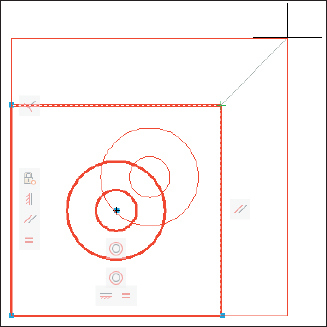
Figure 19-14: Full-on geometric constraints.

 Parametrics was a new feature in AutoCAD 2010, and it got a considerable enhancement in AutoCAD 2011 with the addition of inferred constraints. A status bar button (to the left of the Snap button) toggles Infer Constraints mode off and on. When Infer Constraints mode is enabled, you don't even have to specifically apply geometric constraints. For example, in AutoCAD 2010, if you wanted to make sure the endpoint of a line was always coincident with the center of a circle, you had to select the Coincident tool and click the two points. With inferred constraints, AutoCAD automatically applies a coincident constraint to these two points. Inferred Constraints mode is a powerful component of parametric drafting in AutoCAD, but I recommend that first you make yourself familiar with manually applying constraints in the ways I show in this chapter.
Autoconstrain yourself!
 The geometric constraints listed in Table 19-2 are meant to be applied one at a time. It's great to have that flexibility, but it can be pretty darned time-consuming to go around a complex object, trying to figure out what the best constraint option would be and then applying it.
The Auto Constrain button on the Parametric tab's Geometric panel can apply a whack of constraints to a selection of objects with a single click — but before you execute that single click, it's worth taking a look at the Auto Constrain settings. Click the dialog box launcher (the little arrow at the right end of the Geometric panel label) to open the Constraint Settings dialog box and make the AutoConstrain tab active (see Figure 19-15). Choose which constraints you want to apply automatically, and what order you want them in the list so the ones that should take precedence have a higher priority.
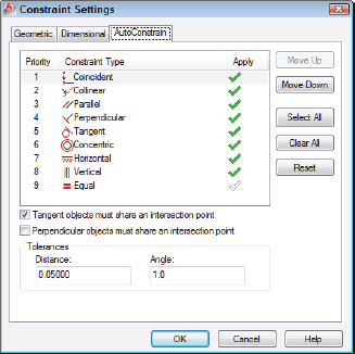
Figure 19-15: Auto-constrainable geometric relations in the Constraint Settings dialog box.
Auto Constrain works only with geometric constraints, not with dimensional constraints.
The three buttons at the right side of AutoCAD's Geometric panel — and the only buttons on AutoCAD LT's Geometric panel — are for controlling the visibility of geometric constraint markers. Show All shows them all, and Hide All (surprise!) hides them all. Use the Show/Hide button to display the constraints on selected objects. This last button is a little clunky. It would be nice to be able to hover the mouse pointer over an object and have the constraints show, but you actually have to click an object and then press Enter to see any results.
In this chapter I present the two varieties of parametric constraints separately, but you'll get the most mileage from this feature when you incorporate both geometric and dimensional constraints with all those other precision techniques I tell you about in Chapter 7. In fact, if you start a drawing using Snap, Ortho, Osnap, and other precision techniques before you start adding dimensional and parametric constraints, you'll be well on the way to creating a library of intelligent drawings that maintain your design intent.