
Understanding Dimensional Constraints
The normal practice in AutoCAD is to create some geometry — of course, using all the precision techniques I discuss in Chapter 7 — and then apply dimensions as I describe in Chapter 14. Assuming that you're using fully associative dimensions, you can then edit the geometry and watch the dimensions update automatically. The length of the line or the radius of the circle are in control, and those dimensions are called driven dimensions because they change when the object geometry changes.
Dimensional constraints, unlike regular AutoCAD dimensions, are driving dimensions, which means that when you change the value of a dynamic dimension on a line, the line changes to match — in other words, the length of the line is being driven by the dimension, not the other way around.
There are only eight dimensional-constraint options, but they cover all the bases. Table 19-1 lists them and describes their purposes.
Table 19-1 Dimensional Constraints

Practice a little constraint
 The objects you add to your drawing from the Dimensional panel are not the same as the dimension objects you add from the Annotate tab. Dimensional constraints are driving dimensions — that means when you change the value of one of these dimensions, the geometry changes.
 A lot is happening behind the scenes as you apply parametric constraints. You can get a great sense of how these constraints work at keeping your drawing objects in order by trying the STRETCH command on objects after you apply a constraint to them.
 You can find the files I use in this sequence of steps at this book's companion web site. Go to www.dummies.com/go/autocad2012 and download afd19.zip. The drawing named afd19a.dwg contains the unconstrained geometry, and drawing afd19b.dwg contains the end product.
The following steps present a very simple example of dimensional constraints:
- Start a new drawing and make the Ribbon's Parametric tab current.
Turn on some appropriate precision drawing aids on the status bar, such as Snap, Ortho, and Osnap.
- Draw some reasonably precise geometry using some of those precision techniques I describe in earlier chapters.
In the following example, I've used the RECTANG and CIRCLE commands to draw the geometry you see in Figure 19-2. The rectangle is 10 units square, and the 2.5-unit-radius circle is deliberately drawn away from the middle of the square.
 On the Dimensional panel of the Parametric tab, click the top part of the Linear split button.
A linear dimension icon appears beside the pickbox and AutoCAD prompts you to specify the first constraint point or pick an object.
Just like the DIMLINEAR command, the Linear dimensional constraint tool is inferential — which way you drag the crosshairs controls whether you get a horizontal or vertical dimension. Also, just like DIMLINEAR, you can press Enter at the command prompt and select an object to dimension.
- Press Enter at the command prompt to confirm you want to select an object and then select the bottom horizontal line segment.
If you see red markers at the midpoint and ends of the bottom line, you didn't press Enter, and you're in point-selection rather than object-selection mode.
AutoCAD generates a preview of a dimensional constraint and prompts you for a location.

- Click to locate the dimension position.
AutoCAD draws a dimensional constraint with a highlighted text field displaying the dimension name (d1 in this example) and the value returned by AutoCAD. You could type a new value in the edit box, but for now, just press Enter to confirm the value and the dimension location (see Figure 19-3).
If your dimensional constraints disappear as soon as you place them, click the Show All button on the Parametric tab's Dimensional panel (as shown in Figure 19-3). Dimensional constraints are not regular dimension objects — they're not going to plot, so it doesn't really matter where you put them or what they look like. (I show you how to turn dimensional constraints into properly styled, plottable dimensions in the next section.) - Repeat Steps 3–5 and add a dimensional constraint to the right vertical edge of the rectangle.
AutoCAD draws a second dimensional constraint, this one named d2.
As you mouse over the Linear button, you can see that unlike its Aligned neighbor, it's split into two parts. You can force a linear dimensional constraint to be either horizontal or vertical (rather than dependent on the direction in which you drag your crosshairs) by clicking the bottom part of the Linear button and making your choice from the drop-down menu.

Figure 19-3: Placing a dimensional constraint.
Making your drawing even smarter
If this were a traditional mechanical drawing that followed the rules of drafting, those two dimensions would be enough — whoever is reading your drawing understands that if sides are parallel and perpendicular, a dimension on one side applies to the opposite side as well. But in this chapter, I'm talking about intelligent drawings that respect design intent, not dumb collections of lines and circles, even if they do follow the rules of drafting!
If you try stretching the rectangle in various ways (from the upper-left corner, for example), you can see that only the bottom and right sides are constrained to 10 units in length. You could add two more linear dimensional constraints to the unconstrained sides, but then you'd have to remember to edit both dimensions. Rather than constraining both sides to be 10 units long, the way to maintain design intent is to make both sides equal in length.
You can make the two sides equal using either dimensional or geometric constraints. It's sometimes a good idea to apply some geometric constraints to your drawing so objects are at least a little locked down. In fact, in a real-world workflow, you'd be using both geometric and dimensional constraints as you produce your design.
I cover geometric constraints in a little more detail in the “Understanding Geometric Constraints” section later in the chapter, but for now, I'm going to apply three geometric constraints so the drawing behaves more predictably.


 On the Geometric panel of the Parametric tab, click Fix (the padlock icon) and click the lower-left corner of the rectangle.
- On the Geometric panel, click Horizontal and click the bottom side of the rectangle. Then click Vertical and click the left side.
Icons appear near the drawing geometry, showing that those three geometric constraints are active (see Figure 19-6 a few pages ahead).
I explain those icons — and geometric constraints, in general — in the next section, but I'm going back to dimensional constraints to finish this drawing.
- On the Dimensional panel of the Parametric tab, click Linear and add a dimensional constraint to the top horizontal line.
- Click to locate the dimension, type d1, and press Enter when AutoCAD prompts for the dimension text.
Instead of having numeric values like the first two linear constraints, this new dimensional constraint displays fx: d3=d1.
 The main part of this expression sets the d3 dimension to equal the value of the d1 dimension. The fx: is there just to remind you that other variables in other dimensions are being referenced.
 - Repeat Steps 3 and 4, this time adding a constraint to the vertical line at the left and entering d2 as the dimension text.
All four dynamic dimensional constraints display their names, plus a value or expression for each.
Dimensional constraints have names as well as values. They can also include expressions or formulas. You can set the default appearance of dynamic dimensional constraints by clicking the dialog-box launcher (the little arrow at the right end of the Dimensional panel label) to open the Constraint Settings dialog box with the Dimensional tab active (see Figure 19-4). The options are
- Name: The first linear dimension is named d1, the second d2, and so forth. You use the dimension names in expressions.
- Value: The numeric value that you enter into the dimensional constraint or that AutoCAD enters if you don't override it.
- Name and Expression: The dimension name shown as equal to an expression. The expression can be a value, as in this example, or it can be a formula.

Figure 19-4: Format the appearance of dimensional constraints in the Constraint Settings dialog box.
Using the Parameters Manager
Both AutoCAD and AutoCAD LT include the Parameters Manager palette, accessible on the Manage panels of their Ribbon's Parametric tab. You can use the Parameters Manager to give all those dimensional constraints more sensible names than d1 and d2, but even more usefully, you can enter expressions instead of plain numeric values, as I explain in the following steps.
 Click Parameters Manager in the Manage panel.
The Parameters Manager palette appears, showing a list of dimensional constraints currently applied in the drawing (see Figure 19-5).
In Figure 19-5, the Expression column shows the numeric values I specified for d1 and d2 and the expressions I entered for d3 and d4. The read-only Value column shows the calculated value. You can't change a value in the Value column (it's grayed out to remind you); you can only edit the cells in the Expression column.
- In the d1 row, click in the Expression field to highlight the current value (10 in this example), then click again and type a new value. For example, type 13 and press Enter.
The rectangle resizes itself in the drawing editor, and because the d3 constraint on the top side was made equal to the d1 constraint on the bottom side, both sides change equally.

Figure 19-5: The Parameters Manager palette.
Next, use an equation as an expression.
- In the d2 row, click in the Expression field to highlight the current value and then type an expression. For example, type d1*0.75 and press Enter.
The read-only Value column and the drawing geometry show that the new d1 distance of 13 has been multiplied by 0.75 and is now 9.75 (see Figure 19-6).

- Close the Parameters Manager.
Finally, constrain the circle so its center is always at dead center of the rectangle, no matter how the rectangle's size changes.
- Apply a horizontal dimensional constraint from the upper-left corner of the rectangle to the center of the circle. Locate the dimension and then type d3/2 and press Enter.
Because the rectangle is now dimensionally constrained on all four sides, it doesn't really matter which corner you start from. And note that you don't have to type the whole expression d5=d3/2. AutoCAD knows what you mean!
- Repeat Step 5, this time adding a vertical constraint from one of the corners to the center of the circle. Locate the dimension and then type d4/2.
Figure 19-7 shows the object geometry with all constraints added in this section. Who knew that drafting could be such fun?

Figure 19-7: All locked down — dimensionally, at least.
If your drawing starts getting overwhelmed with parameters, you can add parameter filters in the Parameters Manager palette. Right-click any parameter and choose Show Filter Tree, or click the double right arrow at the top left of the palette to open the Filters pane. Click the funnel icon in the toolbar to create a new filter group, then simply drag and drop parameters into the group. Figure 19-8 shows the two constraints added in Steps 5 and 6 dragged into a new group filter.

Figure 19-8: Filter your parameters to keep them organized.
Dimensions or constraints — have it both ways!
After all that hard work adding dimensional constraints to your drawings, it would be a downright shame to have to go back and apply regular dimensions, wouldn't it? Well — you don't have to — you can make dimensional constraints look and behave like regular dimensions. You can go the other way too, and make your regular dimensions act like dimensional constraints.
Dimensional constraints are available in two flavors:
- Dynamic constraints: The default form. Dynamic constraints appear gray with a padlock icon next to them in the drawing area. You can make them appear and disappear by clicking Show All in the Dimensional panel. They don't plot, and they resize as you zoom in and out of the drawing so they're always legible.
- Annotational constraints: This form is controlled as an object property, so you have to set it in the Properties palette. Annotational constraints do plot, don't resize as you zoom in and out, and don't disappear as you toggle the Show All button on and off. Annotational constraints conform to dimension style settings.
The dimension name format of annotational constraints can be set to Name, Value, or Name and Expression, just like dynamic constraints (refer to Figure 19-4 for another look at the Constraint Settings dialog box). If you're going to plot your drawing with annotational constraints, remember to reset the format so it doesn't show the dimension name or the expression.
Here's how to turn dynamic dimensional constraints into annotational constraints.
- Open a drawing that contains some geometry with dimensional constraints.
You can also start a new drawing, draw some simple geometry, and add a dimensional constraint to two.
- Select a dynamic constraint, right-click, and choose Properties.
The Properties palette opens with the object properties of the selected dimensional constraint listed in table form.
- Click in the Constraint Form field and in the drop-down list, change Dynamic to Annotational (see Figure 19-9).
The dynamic constraint becomes annotational, and takes on the appearance of the current dimension style. If you change the dimension style in the Properties palette, the annotational constraint updates to the new dimension style format.
You can go the other way too, from regular dimension objects to dimensional constraints.
- Add a linear, radius, diameter, aligned, or angular dimension (that is, a regular dimension, not a dimensional parameter) to your drawing geometry.
Nearly every type of dimension object has a parametric analog; the exceptions are arc length, jogged radius, jogged linear, and ordinate dimensions.
 Click Convert in the Dimensional panel, select one of the dimension types in Step 4, and press Enter.
The Dimensional Constraint text box displays as soon as you click an associative dimension, and the dimension becomes a dynamic constraint as soon as you press Enter.
 The only clue that a dimension is an annotational constraint rather than a regular old associative dimension is the padlock icon that appears next to the dimension value. You can turn off the display of the padlock in the Constraint Settings dialog box, but I recommend you leave it on. It doesn't plot anyway, and you might decide to delete the dimension without realizing it's controlling your object geometry.
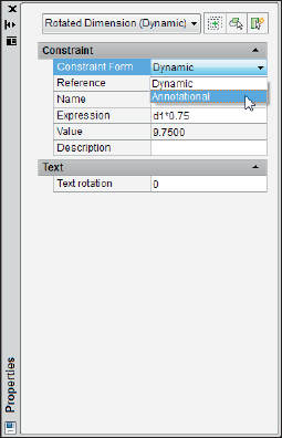
Figure 19-9: Turning dynamic constraints into annotational ones.