
Pushing the Boundary (of) Hatch
The remainder of this chapter shows you how to refine the techniques presented in the preceding section. I describe how to copy existing hatching, take advantage of the various options in the Hatch and Gradient dialog box (which offers a bit more control than the Hatch Creation contextual tab), and choose more complicated hatching boundaries.
Catch a hatch: Copying hatch properties
One slick way to hatch is by using the Match Properties button on the Options panel of the Hatch Creation tab, or the Inherit Properties button in the Hatch and Gradient dialog box, to copy hatch properties from an existing hatch object. Think of it as point-and-shoot hatching. If someone — such as you — added some hatching in the past that's just like what you want to use now, click the Inherit Properties or Match Properties button and pick the existing hatching.
Inherit Properties (Match Properties) updates the hatch pattern settings in the Hatch and Gradient dialog box to make them the same as the existing hatch pattern object that you picked. You can use the cloned hatch pattern specifications as they are or modify them by making changes in the Hatch and Gradient dialog box.
Consistency is a good thing in drafting, especially in computer-aided drafting, in which some or all your drawing may be used for a long time. Thus, it's good to use the same hatch patterns, scales, and angles for the same purposes in all your drawings. Find out whether your project, office, company, or profession has hatching standards that apply to your work.
Hatch from scratch
An alternative to the Ribbon is the Hatch and Gradient dialog box as shown in Figure 15-4. You don't see your hatch object updating as you change settings the way you do with the Ribbon, but you do have a bit more control over what you're going to end up with. To display the Hatch and Gradient dialog box, click the dialog box launcher (the teeny arrow at the right end of the Options panel of the Ribbon's Hatch Creation tab).

Figure 15-4: The Hatch tab of the expanded Hatch and Gradient dialog box.
You can use predefined, user-defined, or custom hatch patterns. Most of the time, you'll choose either predefined or user-defined hatch patterns, unless some generous soul gives you a custom pattern.
 By default, the right third of the Hatch and Gradient dialog box is hidden; to see the additional hatch options at the right side of the dialog box, as shown in Figure 15-4, click the More Options arrow beside the Help button.
Pick a pattern, any pattern: Predefined hatch patterns
To use AutoCAD's predefined hatch patterns, select Predefined from the Type drop-down list at the top of the Hatch tab in the Hatch and Gradient dialog box. This selection sets the stage for choosing the hatch pattern.
You specify a predefined hatch pattern in one of two ways:
- Pattern drop-down list: If you know the name of the hatch pattern, select it from the Pattern drop-down list. The list is alphabetical, except that SOLID (that is, a solid fill) is at the very beginning.
- Pattern button: If you don't know the pattern's name or if you prefer the visual approach, click the Pattern button (the tiny button with the ellipsis [three dots] to the right of the Pattern drop-down list and pattern name) to display the Hatch Pattern Palette with pattern previews and names.
Figure 15-5 shows the some of the Other Predefined hatch patterns, which cover everything from Earth to Escher to Stars.

Figure 15-5: Plenty of hatch patterns.
After you've selected a pattern, specify angle and scale, as I describe in the section, “Getting it right: Hatch angle and scale,” later in this chapter.
Although you may not guess it, AutoCAD treats filling an area with a solid color as a type of hatching. Simply choose SOLID from the top of the Pattern drop-down list.
Like any other object, a solid hatch takes on the current object color — or the current layer's color if you leave color set to ByLayer. Therefore, check whether the current object layer and color are set appropriately before you use the Solid hatching option (see Chapter 6 for details).
AutoCAD's transparency object property is probably most useful (in 2D anyway) when applied to solid hatches. You can use transparent solid hatches to demarcate areas on architectural floor plans or aerial photographs of project sites. In addition to the settings I list in the preceding paragraph, make sure the current object or layer transparency is set correctly too.
It's up to you: User-defined hatches
A user-defined hatch pattern makes a hatch pattern out of parallel lines. Use this option to create a simple pattern and specify the space between the lines in paper units for annotative hatches or drawing units for non-annotative hatches. For example, you can hatch a wall in a building plan with an annotative user-defined pattern and specify that the hatch lines be 1/8″ apart.
After you choose User Defined from the Type drop-down list in the Hatch and Gradient dialog box, you specify the angle and spacing of the lines. You can select the Double check box to achieve a crosshatching effect (two perpendicular sets of hatching lines).
 User-defined patterns require that you enter an angle and spacing, not angle and scale.
Getting it right: Hatch angle and scale
Predefined and custom hatch patterns require that you enter the angle and scale for AutoCAD to generate the hatching. Usually, you won't have any trouble deciding on an appropriate angle, but a suitable scale can be tricky. Because (with a few exceptions) AutoCAD's hatch patterns don't represent real objects, you don't have to be that precise about scaling them — you can just make them look good. But where do you start?
The answer to that question depends on whether you're using AutoCAD's annotative hatching or the old-style, non-annotative hatching. If you're an up-to-the-minute CAD gal or guy, check out the next section, “Hatching for the 21st century.” For non-annotative hatching, you need to calculate the hatch scale based on the drawing scale factor, as described in Chapter 4. As a general rule, hatch patterns look best at somewhere between one-half and three-quarters of the drawing scale factor. For example, the EARTH pattern (in the Other Predefined tab of the Hatch Pattern Palette, as shown in Figure 15-5 and as used in an actual drawing back in Figure 15-1) looks pretty good in a full-scale (1 = 1) drawing with a hatch scale of 0.75. If you're adding EARTH pattern hatching to a 1″ = 1′−0″ detail (drawing scale factor equals 12), try using a hatch scale of 0.75 × 12, or 9.0. Using a consistent multiplier like 0.5 or 0.75 applied to the drawing scale factor ensures that hatching looks consistent (that the spaces between the lines are the same) at all scales when you plot.
Autodesk created the hatch patterns whose names begin with AR- particularly for use in architectural drawings, and unlike the non-AR patterns, they do represent real objects such as brick and roof shakes. The AR-patterns were designed with a final hatch scale of 1.0 in mind, but in some cases, you'll have to adjust up or down in order to achieve a suitable scale.
Hatching for the 21st century
With annotative hatching, you start with the paper scale (because that's where all your fancy CAD geometry is going to end up) of 1:1. Once again, most patterns look better at between half and three-quarters of the paper scale, so try setting the hatch scale to, say, 0.75. The following steps explain how to create annotative hatching:
 You can find the files I use in this sequence of steps at this book's companion web site. Go to www.dummies.com/go/autocad2012 and download afd15.zip. The drawing named afd15a.dwg contains the architectural detail shown in Figure 15-6.
- Open a drawing containing geometry that forms fully closed boundaries, or draw some boundaries by using the drawing commands described in Chapters 8 and 9.
The areas you want to hatch should be completely enclosed. The CIRCLE, POLYGON, and RECTANG commands, and the LINE and PLINE commands with the Close option, make great hatch boundaries (see Chapters 8 and 9 for details).
- Set an appropriate layer current, as described in Chapter 6.
- Start the HATCH command by typing H and pressing Enter. Alternatively, click the Hatch button on the Draw panel of the Ribbon's Home tab.
AutoCAD prompts:
Pick internal point of [Select objects/seTtings]:
- Type T to select the seTtings option and press Enter.
The Hatch and Gradient dialog box as seen in Figure 15-4 appears.
- Choose Predefined, User Defined, or Custom from the Type drop-down list.
Predefined works best for most purposes. See the “Hatch from scratch” section, earlier in this chapter, for details.
- If you chose Predefined or Custom in the previous step, select any predefined or custom hatch pattern from the Pattern drop-down list.
If you chose User Defined, you don't need to choose a pattern.
- Specify an Angle and Scale for the hatch pattern. (Or, if you chose User Defined in Step 5, specify Angle and Spacing.)
See the previous section, “Getting it right: Hatch angle and scale,” for more information.
- In the Options area of the dialog box, select the Annotative check box.
This time you're going to create annotative hatch objects.
- Click the Add: Pick Points button.
The Hatch and Gradient dialog box (temporarily) disappears, and your drawing reappears with the following prompt at the command line:
Pick internal point or [Select objects/seTtings]:
- Pick a point inside the boundary of the area you want to hatch.
AutoCAD analyzes the drawing and decides which boundaries to use. In a complex drawing, this analysis can take several seconds. AutoCAD highlights the boundary that it finds and previews the hatched area.
- Right-click anywhere in the drawing area and choose Enter from the menu to indicate that you're finished selecting points.
AutoCAD hatches the area inside the boundary. If you've correctly created an annotative hatch object, you see the annotative object symbol (the end of a triangular drawing scale) beside the crosshairs if you move your crosshairs over the hatch.
- Select the hatch object; then right-click and choose Annotative Object Scale, then Add/Delete Scales to assign annotative scales to the hatch object.
The Annotation Object Scale dialog box appears, showing a list of all annotative scales assigned to the selected object. In the case of a new hatch object, the only scale listed will be the current annotation scale; if you're doing this in a new drawing, the scale will probably be 1:1, the default value.
- In the Annotation Object Scale dialog box, click Add.
The Add Scales to Object dialog box appears, displaying a list of all drawing scale values stored in the drawing.
- Select the desired scales from the list, holding down the Ctrl key to select more than one, and then click OK.
The Annotation Object Scale dialog box reappears, with the scales you added displayed in the list box.
Don't go overboard and select every scale in the list — select only the scales you're likely to use. - Click OK.
After you've assigned annotative scales to a hatch (or any annotative) object, you see a pair of triangular annotative object symbols. Don't worry — although you are seeing double, you've done it right!
- Open the Annotation Scale drop-down list on the application or drawing status bar and select one of the scales you added to the object.
The annotative hatch objects will change their spacing as you change the annotation scale. If you select a scale from the list that you didn't assign to the object in Step 14, the hatch reverts to the default 1:1 scale.
Figure 15-6 shows two versions of the same drawing, dressed up with annotative and non-annotative hatch patterns. As the annotation scales displayed on the drawing status bars show, the annotative hatches change their scale while the non-annotative hatches remain unchanged. Before annotative hatching first appeared in AutoCAD 2008, the only way to get the effect in these two views was to create two separate layers, one for each hatch scale, and hatch the object twice.
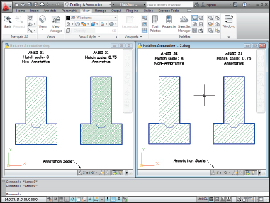
Figure 15-6: Hatches annotative (and not).
Do fence me in: Defining hatch boundaries
After you specify the hatch pattern, angle, and scale you want to use, you define the boundary (or boundaries) into which you want to pour that hatch pattern in one of two ways:
- Picking points within the area(s) you want hatched
- Selecting objects that surround those areas
The actual operation involved in using either of these options is confusing to most people. You'll probably need a little practice before you get used to it.
The idea behind either definition option is simple when applied to simple areas — that is, closed areas with no additional objects inside them. To define the hatch boundary for a simple area, do one of these two things:
- Click the Add: Pick Points button in the Hatch and Gradient dialog box and then click a point inside the boundary.
- Click the Add: Select Objects button and select one or more objects that form a fully closed boundary.
This simple hatching gets more complicated if you have one closed object inside another, as shown in Figure 15-7. The AutoCAD hatch preview and a bit of experimentation will clarify all these potentially puzzling permutations.
As I warn earlier in this chapter, boundaries must be completely closed before AutoCAD will hatch them. That's one of the reasons you should employ the precision techniques from this book whenever you draw or edit objects. If the lines surrounding your boundary don't either meet exactly or cross, AutoCAD scolds you with an A Closed Boundary Could Not Be Determined error message.
The A Closed Boundary Could Not Be Determined error message means that you need to repair lines or other objects so they're a fully closed boundary. Sometimes you can use the FILLET command with a zero fillet radius to force two lines to meet exactly. Another possibility is to use grip editing to align one endpoint precisely with another. Chapter 10 discusses these two editing techniques.
AutoCAD 2010 made grip-editing non-associative hatches a breeze — in fact, they became easier to manage than associative hatches. AutoCAD 2011 added grip functions that make associative and non-associative hatches easy to edit. Hovering your mouse pointer over the round center grip (in AutoCAD 2011 and AutoCAD LT 2011 and later) gives you quick access to changing the hatch origin, angle, and scale, all without running the HATCHEDIT command. Don't be misled by the Stretch option on the right-click menu, though — you can only move a hatch with this option.

Figure 15-7: Get picky about your hatching. (X indicates a pick point.)
Have palette, will hatch
With tool palettes (described in Chapter 2), you can create click-and-drag hatch palettes. With a hatch palette, you click a tool (a swatch) and drag into an enclosed boundary to hatch the area. If your hatching needs are simple, you can create a tool palette for the patterns and scales you often use. See hatches, adding to tool palettes in AutoCAD's online help for more information.