
Managing Your Properties
All the objects that you draw in AutoCAD are like good Monopoly players: They own properties. In AutoCAD, these properties aren't physical things; they're an object's characteristics, such as layer, color, linetype, lineweight, transparency, and plot style. You use properties to communicate information about the characteristics of the objects you draw, such as the kinds of real-world objects they represent, their materials, their relative location in space, or their relative importance. In AutoCAD, you also use properties to organize objects for editing and plotting purposes.
 You can view — and change — all properties of an object in the Properties palette, and many of them in Quick Properties palette. In Figure 6-1, the Properties palette at the left and the Quick Properties palette at the right show properties for the selected line object.
 The Properties palette was joined in AutoCAD 2009 by its more streamlined little sibling, Quick Properties. When Quick Properties is toggled on in the status bar, selecting an object opens a floating palette that displays a customizable selection of that object's properties. (If your status bar buttons show text rather than icons, look for the QP button.)
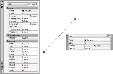
Figure 6-1: Comprehensive or quick? Sometimes you need lots of information, and sometimes you don't.
 Handy as it is, the Quick Properties palette has a knack of popping up on top of drawing objects that you need to see. In AutoCAD 2012, you can keep Quick Properties mode toggled off at the status bar, and instead use the new QUICKPROPERTIES command. Type QP and select an object to display the Quick Properties panel. You can also double-click most objects to display their quick properties.
To toggle the full Properties palette on and off, click the Properties button on the View tab of the Ribbon or use the Ctrl+1 key combination. Before you select an object, the Properties palette displays the current properties — properties that AutoCAD applies to new objects when you draw them. After you select an object, the Properties palette displays the properties for that object. If you select more than one object, the Properties palette displays the properties that they have in common.
Putting it on a layer
Every object has a layer as one of its properties. You may be familiar with layers — independent drawing spaces that stack on top of each other to create an overall image — from using drawing programs. AutoCAD, like most CAD programs, uses layers as the primary organizing principle for all the objects that you draw. You use layers to organize objects into logical groups of things that belong together; for example, walls, furniture, and text notes usually belong on three separate layers, for a couple of reasons:
- Layers give you a way to turn groups of objects on and off — both on the screen and on the plot.
- Layers provide the most efficient way of controlling object color, linetype, lineweight, transparency, and plot style.
So, to work efficiently in AutoCAD, you create some layers, assigning them names and properties, such as color and linetype. Then you draw objects on those layers. When you draw an object, AutoCAD automatically puts it on the current layer — the layer that you see in the Layer drop-down list on the Home tab's Layers panel when no objects are selected. If a layer already exists in your drawing, you can make it the current layer by choosing it in the Layer drop-down list, as shown in Figure 6-2.
 It's not absolutely necessary to create all your layers before you draw anything, but it will save you some time if you start with a few basic layers and then add new layers as needed. Many experienced AutoCAD users draw things first and then create appropriate layers and change the objects to the new layers. You can easily change an object's layer by selecting it and then choosing the desired new layer name from the Layer drop-down list.

Figure 6-2: Setting an existing layer as the current layer.
 Make sure that no objects are selected before you use the Layer drop-down list to change the current layer. (Press the Esc key twice to be sure.) If objects are selected, the Layer drop-down list displays (and lets you change) those objects' layers. When no objects are selected, the Layer drop-down list displays (and lets you change) the current layer.
How do you decide what to call your layers and which objects to put on them? Some industries have developed layer guidelines, and many offices have created documented layer standards. Some projects even impose specific layer requirements. (But be careful; if someone says, “You need a brick layer for this project,” that can mean a couple of different things.) Ask experienced CAD drafters in your office or industry how they use layers in AutoCAD. If you can't find any definitive answer, create a chart of layers for yourself. Each row in the chart should list the layer name, default color, default linetype, default lineweight, default transparency, and what kinds of objects belong on that layer. If you use named plot styles to control your plotted output, add a default plot style to the list — that's not necessary for traditional color-based plotting.
Accumulating properties
Besides layers, the remaining object properties that you're likely to want to use often are color, linetype, lineweight, transparency, and possibly plot style. Table 6-1 summarizes these five properties.
Table 6-1 Useful Object Properties
| Property | What It Controls |
| Color | Displayed color and plotted color or line width |
| Linetype | Displayed and plotted dash-dot line pattern |
| Lineweight | Displayed and plotted line width |
| Transparency | Displayed and plotted opacity of objects |
| Plot style | Plotted characteristics (see Chapter 16) |
Long before AutoCAD could display lineweights on the screen and print those same lineweights on paper, object colors controlled the printed lineweight of objects. AutoCAD 2000 introduced a more logical system, where you could assign an actual plotted thickness to objects. As logical as that method seems, the older method, in which the color of objects determines their plotted lineweight, continues to dominate. You may find yourself working this way even in AutoCAD 2012, for compatibility with drawings (and coworkers) that use the old way. Figure 6-3 shows you the idea. The model space view at the left shows objects in different colors, but with the same default lineweight. The paper space view at the right (what your plotted drawing will actually look like) shows that, although the lines are all black, their thicknesses vary, determined by the model space colors. For example, Blue is very thick and Black is very thin.
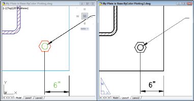
Figure 6-3: Change my line thickness but color me black.
AutoCAD gives you two different ways of controlling object properties:
- By Layer: Each layer has a default color, linetype, lineweight, transparency, and plot style property. Unless you tell AutoCAD otherwise, objects inherit the properties of the layers on which they're created. When objects are selected in a drawing created using this system, the object properties are listed as ByLayer.
- By Object: AutoCAD also enables you to override an object's layer's property setting and give the object a specific color, linetype, lineweight, transparency, or plot style that differs from the layer's.
If you've worked with other graphics programs, you may be used to assigning properties, such as color, to specific objects. If so, you may be tempted to do the same in AutoCAD. Resist the temptation. Did you catch that? One more time: Resist the temptation.
In almost all cases, it's better to create layers, assign properties to each layer, and let the objects on each layer inherit that layer's properties. Here are some benefits of using the ByLayer approach:
- You can easily change the properties of a group of related objects that you put on one layer. You simply change the property for the layer, not for a bunch of separate objects.
- Experienced drafters use the ByLayer approach, so if you work with drawings from other people, you'll be much more compatible with them if you do it the same way. You'll also avoid getting yelled at by irate CAD managers, whose job duties include haranguing any hapless newbie who assigns properties to individual objects.
If you take my advice and assign properties ByLayer, all you have to do is set layer properties in the Layer Properties Manager palette (I tell you how in this section), as shown in Figure 6-4. Before you draw any objects, make sure the Color Control, Linetype Control, and Lineweight Control drop-down lists, and the Transparency button on the Ribbon Home tab's Properties panel are all set to ByLayer, as shown in Figure 6-5. (Remember that the configuration of panels and drop-down lists may vary according to the resolution of your display.) If the drawing is set to use color-based plot styles instead of named plot styles (see Chapter 16), the Plot Style Control drop-down list will be inactive and will display ByColor.
Figure 6-4: Use layer properties to control object properties.

Figure 6-5: ByLayer (nearly) all the way.
 As with all palettes in AutoCAD, you can leave the Layer Properties Manager open while you do other things in the drawing — unlike the dialog box method of stopping what you're doing, opening the dialog box, making adjustments, closing the dialog box, and then resuming what you were doing. Also like other palettes, the Layer Properties Manager can be set to auto-hide itself to its title bar, to be either floating or docked, or to be anchored (do you get the sense that there are some AutoCAD programmers who'd rather be sailing?) to either side of the screen.
If the drawing is set to use named plot styles instead of color-based plot styles (see Chapter 16), the Plot Style control drop-down list should also display ByLayer.
If you want to avoid doing things the wrong way and getting yelled at by CAD managers, don't assign properties to objects in either of these ways:
- Don't make the very common beginner's mistake of choosing a specific color, linetype, lineweight, transparency, or plot style from the appropriate drop-down list on the Properties panel of the Ribbon's Home tab, or from the Properties palette, and then drawing the objects.
- Don't make the also-very-common beginner's mistake of drawing the objects, selecting them, and then choosing a property from the same drop-down lists.
If you prefer to do things the right way (that is, my way!), assign these properties ByLayer, as I describe in the following section.
AutoCAD's SETBYLAYER command lets you correct those non-ByLayer properties — on the Ribbon's Home tab, click the Modify panel label to open the panel slideout, and then click Set to ByLayer. Answer the prompts at the command line to finish modifying objects. For more information, refer to SETBYLAYER in the online help.
Creating new layers
If a suitable layer doesn't exist, you need to create one in the Layer Properties Manager palette. Follow these steps:
- Click the Layer Properties button on the Layers panel of the Ribbon's Home tab, or type LAYER (or LA) at the command line and press Enter.
The Layer Properties Manager palette appears. A new drawing has only one layer: Layer 0. You need to add the layers necessary for your drawing.
- Click the New Layer button (it looks like a sheet of paper with a little sunburst on one corner) to create a new layer.
A new layer appears. AutoCAD names it Layer1 but highlights the name in an edit box so you can type a new name to replace it easily, as shown in Figure 6-6.

Figure 6-6: Adding a new layer in the Layer Properties Manager palette.
- Type a name for the new layer.
Type the layer name with initial caps (only the first letters of words in uppercase). Layer names written completely in uppercase are much wider, which means that they often get truncated in the Layer Control drop-down list.
- On the same line as the new layer, click the color block or color name (White by default) of the new layer.
The Select Color dialog box appears, as shown in Figure 6-7.

Figure 6-7: The Select Color dialog box. Magenta is selected from the Standard Colors list.
The normal AutoCAD color scheme — AutoCAD Color Index (ACI) — provides 255 colors. So many choices are overkill for ordinary drafting.
For now, stick with the first nine colors — the ones that appear in a single, separate row to the left of the ByLayer and ByBlock buttons on the Index Color tab of the Select Color dialog box — for the following reasons:- These colors are easy to distinguish from one another.
- Using a small number of colors makes configuring your plot parameters easier. (I describe that procedure in Chapter 16.)
 In the Select Color dialog box, the True Color tab offers a choice of more than 16 million colors, which you can specify by using HSL (Hue Saturation Luminance) or RGB (Red Green Blue) numbers. The Color Books tab enables you to use PANTONE and RAL color schemes, which are popular in publishing. If your work requires tons of colors or close color matching between the computer screen and printed output, you're probably familiar with the relevant color palette and how to use it. If you're using AutoCAD for ordinary drafting or design, stick with the AutoCAD Color Index palette.
 - Click a color to select it as the color for this layer and click OK.
The Select Color dialog box closes, and focus returns to the Layer Properties Manager palette. In the Color column, the new layer color changes to either the name or the number of the color that you selected.
AutoCAD's first seven colors have both numbers and standard names: 1 = red, 2 = yellow, 3 = green, 4 = cyan, 5 = blue, 6 = magenta, and 7 = white (which appears black when displayed on a white background). The remaining 248 colors have numbers only. - On the same line as the new layer, click the Linetype name of the new layer.
The Select Linetype dialog box appears, as shown in Figure 6-8.
The default AutoCAD linetype is Continuous, which means no gaps in the line.
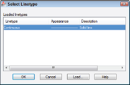
Figure 6-8: The Select Linetype dialog box.
If you already loaded the linetypes you need for your drawing, or if the template file you started from has some linetypes loaded, the Select Linetype dialog box displays them in the Loaded Linetypes list. If not, click the Load button to open the Load or Reload Linetypes dialog box. By default, AutoCAD displays linetypes from the standard AutoCAD or AutoCAD LT linetype definition file — acad.lin for imperial-units drawings or acadiso.lin for metric-units drawings (acadlt.lin and acadltiso.lin in AutoCAD LT). Load the desired linetype by selecting its name and clicking OK.
Unless you have a really good reason (for example, your boss tells you so), avoid loading or using any linetypes labeled ACAD_ISO. These linetypes are normally used only in metric drawings — and rarely even then. They overrule everything I'm trying to show you about printed lineweight in what follows so, if at all possible, just say NO to ACAD_ISO. I promise you'll find it easier to use the linetypes with the more descriptive names: CENTER, DASHED, and so on. - Click the desired linetype in the Loaded Linetypes list to select it as the linetype for the layer; say that really fast five times and then click OK.
The Select Linetype dialog box disappears, returning you to the Layer Properties Manager palette. In the Name list, the linetype for the selected layer changes to the linetype you just chose.
- On the same line as the new layer, click the new layer's lineweight.
The Lineweight dialog box appears, as shown in Figure 6-9.

- Select the lineweight you want from the list and click OK.
Using the lineweight property is a two-step process. After you've assigned a lineweight to a layer, you must click the Show/Hide Lineweight button on the status bar to see the effect. You can toggle the feature off and on with this button.
The lineweight 0.00 mm tells AutoCAD to use the thinnest possible lineweight on the screen and on the plot. I recommend that for now, you leave lineweight set to Default and instead map screen color to plotted lineweight, as described in greater detail in Chapter 16.AutoCAD 2012's transparency property will probably be most appreciated by people preparing drawings for presentation. Clicking in the Transparency column opens the Layer Transparency dialog box; type a numeric value between 0 and 90 or use the drop-down list to set a value. Transparency = 0 is the default, and means no transparency at all — objects drawn on a layer set to Transparency = 0 are completely opaque. Set the value to greater than 0 and you start seeing things through the objects you draw.
- In the same line as the new layer, click the value in the Transparency column.
By default, layer transparency is set to 0, for no transparency. As you increase the numeric value, the degree of transparency increases (the maximum value is 90). Similar to the Lineweight property, you have to turn on the Transparency button on the status bar to see through your objects.
The Plot Style column's contents depend on whether the drawing uses named plot styles or the traditional color-based plotting. Drawings set up to use color-based plotting display an unchangeable plot style name based on the layer's color property. The grayed-out style name changes only when the layer color changes. If, on the other hand, your drawing uses named plot styles, you can assign a named plot style to the layer in this column. (Chapter 16 explains why you might not want to.)
The setting in the Plot column controls whether the layer's objects appear on plots. Click the little printer icon to toggle this setting off (the little printer gets a red bar through it) for any layer whose objects you want to see on the screen but hide on plots.
- (Optional) If you want to add a description to the layer, scroll the layer list to the right to see the Description column, click in the Description box corresponding to your new layer, and type a description.
My advice is to name your layers so you can tell what's on them. If you do choose to use layer descriptions, stretch the Layer Properties Manager palette to the right so that you can see the descriptions without having to scroll the layer list.
- Repeat Steps 1 through 11 to create any other layers that you want.
- Select the new layer that you want to make current and click the Set Current button (the green check mark).
Changes you make in the Layer Properties Manager palette are instantaneous, unlike a dialog box in which you have to click OK to close the dialog box and apply the change.
 Don't forget to toggle on the Lineweight and Transparency buttons on the status bar to see the effect of assigning these properties. Unlike color and linetype, lineweight and transparency can be switched off and on.
The Layer Control drop-down list now displays your new layer as the current layer — the one on which AutoCAD places new objects that you draw.
After you create layers, you can set any one of them to be the current layer: Make sure that no objects are selected, and then choose the layer name from the Layer Control drop-down list on the Layers panel in the Ribbon or the Layers toolbar.
A load of linetypes
When you load a linetype, AutoCAD copies its linetype definition — a formula for how to create the dashes, dots, and gaps in that particular linetype — from the acad.lin (imperial units) or acadiso.lin (metric units) file into the drawing. (The files are acadlt.lin and acadltiso.lin, respectively, in AutoCAD LT.) The definition doesn't automatically appear in other drawings; you have to load each linetype that you want to use into each drawing in which you want to use it. If you find yourself loading the same linetypes repeatedly into different drawings, consider adding them to your template drawings instead. (See Chapter 4 for information about templates and how to create them.) After you add linetypes to a template drawing, all new drawings that you create from that template will start with those linetypes loaded automatically.
Don't go overboard on loading linetypes. For example, you don't need to load all the linetypes in the acad.lin file on the off chance that you might use them all someday. The resulting linetype list would be long and unwieldy. Most drawings require only a few linetypes, and most industries and companies settle on a half dozen or so linetypes for common use. Your industry, office, or project may have guidelines about which linetypes to use for which purposes.
If you're the techno-dweeb type and don't mind editing a text file that contains linetype definitions, you can define your own linetypes or weed out the ones you'll never use. Press F1 to open the main online help window. Then choose Customization Guide![]() Custom Linetypes.
Custom Linetypes.
Manipulating layers
After you create layers and draw objects on them, you can turn a layer off or on to hide or show the objects on that layer. In the Layer Properties Manager palette, the first three icons to the right of the layer name control AutoCAD's layer visibility modes:
- Off/On: Click the light-bulb icon to toggle visibility of all objects on the selected layer. AutoCAD does not regenerate the drawing when you turn layers back on. (I give you the lowdown on regenerations in Chapter 12.)
- Freeze/Thaw: Click the sun icon to toggle off visibility of all objects on the selected layer. Click the snowflake icon to toggle visibility on. AutoCAD regenerates the drawing when you thaw layers.
- Lock/Unlock: Click the padlock icon to lock and unlock layers. When a layer is locked, you can see but not edit objects on that layer.
You can rearrange column order by simply dragging and dropping the column label to a new place. And you can right-click any column label to display a menu from which you can turn columns off and on.
Off/On and Freeze/Thaw do almost the same thing — both settings let you make objects visible or invisible by layer. In the old days, turning layers off and on was often a faster process than thawing frozen layers because thawing layers always required regenerating the drawing. But modern computers, modern operating systems, and recent AutoCAD releases make regenerations much less of an issue on all but the largest drawings. You'll probably find it makes no appreciable difference whether you freeze and thaw layers or turn them off and on.
You can turn layers off and on, freeze and thaw them, and lock and unlock them by clicking the appropriate icons in the Layer Control drop-down list on the Ribbon.
The state of your layers
Say you have a floor plan of a house that includes a layer showing the framing and another layer showing the wiring. You'd probably never show both of those elements on the same drawing, so you'd need to do some layer management when you showed your drawing to the framers or the electricians. Rather than turning a dozen layers off and a different dozen layers on when you want a different view into your drawing, you can save groups of layer settings as a named layer state. You can manage your layer states in the appropriately named Layer States Manager dialog box by clicking the Layer States Manager button in the Layer Properties Manager. You can also access the Layer States Manager directly by entering LAYERSTATES at the command line or choosing Manage Layer States from the Layer State drop-down list in the Layers panel.
AutoCAD fades locked layers, giving you a really effective visual reference without confusing you about which layers might be locked or not. You can control the amount of fading by setting a nonzero value for the system variable LAYLOCKFADECTL. (See Chapter 26 for an explanation of system variables and check out the online help for specific info on this one.) You can turn off fading but retain the current setting for future use by adding a minus sign (−) in front of the fade value, or you can turn off the fading altogether by setting this value to 0.
If you find yourself using lots of layers, you can create layer filters to make viewing and managing the layer list easier. A group filter is simply a subset of layers that you choose (by dragging layer names into the group filter name or by selecting objects in the drawing). A property filter is a subset of layers that AutoCAD creates and updates automatically according to layer property criteria that you define (for example, all layers whose names contain Wall or whose color is green). To find out more, move your mouse pointer into the Layer Properties Manager palette, press F1, and click the New Property Filter hyperlink.
In both AutoCAD and AutoCAD LT, you can access a set of layer tools through the Layers panel of the Ribbon's Home tab — see Figure 6-10 (you may have to open the panel slideout to see them all). Layer Isolate and Layer Off are especially useful — you simply click an object to specify the layer to isolate (that is, fade all layers except the chosen one) or turn off altogether. For more information on layers, open the online help system and choose User's Guide![]() Create and Modify Objects
Create and Modify Objects![]() Control the Properties of Objects
Control the Properties of Objects![]() Work with Layers
Work with Layers![]() Use Layers to Manage Complexity.
Use Layers to Manage Complexity.

Figure 6-10: Tooling through the layer tools.
The LAYISO command incorporates the same layer-fading feature described in the preceding tip for locked layers — and it locks the layers as well. Set it up the way you want by typing S (for Settings) and pressing Enter; then type the option letter for the specific settings you want. Look up LAYISO in the online help Index for more information.
Instead of turning off a layer when there are only a few things in the way, you can hide or isolate individual objects with AutoCAD 2012's ISOLATEOBJECTS and HIDEOBJECTS commands while keeping normal visibility for other objects on the layer. I discuss these commands in Chapter 10.