
A Setup Roadmap
You have to set up AutoCAD correctly, partly because AutoCAD is so flexible and partly because, well, you're doing CAD — computer-aided drafting (or design). The computer can't aid your drafting (or design) if you don't clue it in on things like system of measure, drawing scale, paper size, and units. In this context, the following facts help explain why AutoCAD drawing setup is important:
- Electronic paper: The most important thing you can do to make using AutoCAD fun is to work on a correctly-set-up drawing so that your screen acts like paper, only smarter. When drawing on real paper, you constantly have to translate between units on the paper and the real-life units of the object you're drawing. But when drawing in AutoCAD's smarter paper, you draw directly in real-life units — feet and inches, millimeters, or whatever you typically use on your projects. AutoCAD can then calculate distances and dimensions for you and add them to the drawing. You can make the mouse pointer jump directly to preset intervals on-screen, and a visible, resizable grid gives you a better sense of the scale of your drawing. However, this smart-paper function works well only if you tell AutoCAD some crucial parameters for your specific drawing. AutoCAD can't really do its job until you tell it how to work.
- Dead-trees paper: Creating a great drawing on-screen that doesn't fit well on paper is all too easy. After you finish creating your drawing on the smart paper that AutoCAD provides on-screen, you usually have to plot it on the good old-fashioned real-world paper that people have used for thousands of years. At that point, you must deal with the fact that people like to use certain standard paper sizes and drawing scales. (Most people also like everything to fit neatly on one sheet of paper.) If you set up AutoCAD correctly, good plotting is the automatic result; if not, plotting time can become one colossal hassle.
- It ain't easy: AutoCAD provides templates and Setup Wizards for you, but the templates don't work well unless you understand them, and some of the wizards don't work well even if you do understand them. This deficiency is one of the major weaknesses in AutoCAD. You must figure out on your own (with the help of this book, of course) how to make the program work right. If you just plunge in without carefully setting up, your drawing and printing efforts are likely to wind up a real mess.
Fortunately, setting up AutoCAD correctly is a bit like following a roadmap to a new destination. Although the directions for performing your setup are complex, you can master them with attention and practice. Even more fortunately, this chapter provides a detailed and field-tested route. And soon, you'll know the route like the back of your hand.
 While you're working in AutoCAD, always keep in mind what your final output should look like on real paper. Even your first printed drawings should look just like hand-drawn ones — only without all those eraser smudges.
Before you start the drawing-setup process, you need to make decisions about your new drawing. The following four questions are absolutely critical; if you don't answer them or your answers are wrong, you'll probably need to rework the drawing later:
- What system of measure — metric or imperial — will you use?
- What drawing units will you use?
- At what scale — or scales — will you plot it?
- On what size paper does it need to fit?
In some cases, you can defer answering one additional question, but it's usually better to deal with it up front: What kind of border or title block does your drawing require?
 If you're in a hurry, it's tempting to find an existing drawing that was set up for the drawing scale and paper size that you want to use, make a copy of that DWG file, erase the objects, and start drawing. Use this approach with care, though. When you start from another drawing, you inherit any setup mistakes that may lurk in that drawing. Also, drawings that were created in much older versions of AutoCAD may not take advantage of current program features and CAD practices. If you can find a suitable drawing that was set up in a recent version of AutoCAD by an experienced person who was conscientious about doing setup right, then consider using it. Otherwise you're better off setting up a new drawing from scratch.
Choosing your units
AutoCAD is extremely flexible about drawing units; it lets you have them your way. Usually, you choose the type of units that you normally use to talk about whatever you're drawing: feet and inches for a building in the United States, millimeters for a metric screw, and so on.
Speaking of millimeters, there's another choice you have to make even before you choose your units of measure, and that's your system of measure.
… or, “Let's forget everything we learned about measuring stuff and start over again!” All (well, nearly all) the world is metric. Instead of a system of linear measure based on twelves, of volume measure based on sixteens, and of temperature measure based on who knows what, metric bases all types of measure on tens. (Of course, For Dummies books are in the metric vanguard because every single For Dummies title includes a Part of Tens.)
The metric system first gained a toehold (ten toes, of course) in France during the Revolution. Over time, it became apparent that some standardization was called for, and a mere century and a half later, SI Metric became that standard. SI is short for Systeme International d'Unites. (That's International System of Units in English. Isn't it great to speak more than one language?)
The United States may be late coming to the party, but the U.S. federal government has made a commitment to adopt SI Metric. For more information, point your browser to the National Institute of Standards and Technology's Special Publication 814 (http://ts.nist.gov/WeightsAndMeasures/Metric/pub814.cfm).
Most of the world abandoned local systems of measure generations ago. Even widely adopted ones like the imperial system have mostly fallen by the wayside, just like their driving force, the British Empire. Except, of course, in the United States, where feet, inches, pounds, gallons, and degrees Fahrenheit still rule.
During drawing setup, you choose settings for Length units (for measuring linear objects and distances) and Angle units (for measuring angles between nonparallel objects or points on arcs or circles) in the Drawing Units dialog box, as shown in Figure 4-1. (I show you how to specify these settings in the section “Setting your units,” later in this chapter.) AutoCAD's Length unit types are as follows:
- Architectural units are based in feet and inches and use fractions to represent partial inches.
- Decimal units are unitless — that is, they're not based on any particular real-world unit. With decimal units, each unit in the drawing could represent an inch, a millimeter, a cubit (if you're into building arks in case that rainy day should come), or any other unit of measure you deem suitable.
- Engineering units are based in feet and inches and use decimals to represent partial inches.
- Fractional units, like decimal units, are unitless and show values as fractions rather than decimal numbers.
- Scientific units are also unitless and show values as exponents, used for drawing really tiny or really large things. If you design molecules or galaxies, this is the unit type for you.
AutoCAD's Angle unit types are as follows:
- Decimal Degrees show angles as decimal numbers and are by far the easiest to work with — if your type of work allows it!
- Deg/Min/Sec is based on the old style of dividing a degree into minutes and minutes into seconds. But seconds aren't fine enough to display AutoCAD's precision capabilities, so seconds can be further divided into decimals.
- Grads and Radians are mathematically beautiful (so I'm told) but are not widely used in drafting. Apparently the French artillery uses grads, but as long as we're friends with them, we shouldn't have to worry.
- Surveyor's Units type is similar to Deg/Min/Sec, but uses quadrants (quarter circles), rather than a whole circle, where an angle in Deg/Min/Sec might measure 300°0′0.00″, the same angle in Surveyor's Units would be represented as S 30°0′0.00″ E.
For the great majority of AutoCAD users, the unit types to know and use are Decimal, Architectural, and Decimal Degree. You'll know or be told if you need to use one of the other types!

Figure 4-1: The Drawing Units dialog box.
After you specify a type of unit, you draw things on-screen at full size in those units just as though you were laying them out on the construction site or in the machine shop. You draw an 8-foot-high line, for example, to indicate the height of a wall and an 8-inch-high line to indicate the cutout for a doggie door (for a dachshund, naturally). The on-screen line may actually be only 2 inches long at a particular zoom magnification, but AutoCAD stores the length as 8 feet. This way of working is easy and natural for most people for whom CAD is their first drafting experience, but it seems weird to people who've done a lot of manual drafting. If you're in the latter category, don't worry; you'll soon get the hang of it.
 When you use dash-dot linetypes (Chapter 6) and hatching (Chapter 15) in a drawing, it matters to AutoCAD whether the drawing uses an imperial (inches, feet, miles, and so on) or metric (millimeters, meters, kilometers, and so on) system of measure. The MEASUREMENT system variable controls whether the linetype and hatch patterns that AutoCAD lists for you to choose from are scaled with inches or millimeters in mind as the plotting units. MEASUREMENT=0 means inches (that is, an imperial-units drawing), whereas MEASUREMENT=1 means millimeters (that is, a metric-units drawing). If you start from an appropriate template drawing (as described in the section “A Template for Success,” later in this chapter), the MEASUREMENT system variable will be set correctly, and you won't ever have to think about it. (For an explanation of system variables and how to set them, see Chapter 26.)
Weighing up your scales
The next decision you should make before setting up a new drawing is choosing the scale at which you'll eventually plot the drawing. This decision gives you the drawing scale and drawing scale factor — two ways of expressing the same relationship between the objects in the real world and the objects plotted on paper.
The scale factor factor
“Okay,” you're saying, “I understand I need to print my drawings at a scale acceptable to the discipline I work in. But if I'm drawing stuff full size, why do I need to worry about the scale factor?” Grab yourself a nice mug of cocoa and settle down 'round the fire, because I'm going to tell you. By now you know (because I've told you so) that you draw real things full size, but drawings contain other things that are not real, such as text, dimensions, hatch patterns, title blocks, dash-dot linetypes, and so forth. And those nonreal things need to be legible on your plotted drawing.
Say, for example, you want to draw a plan of your garage. You need it to fit on an 11-×-17-inch sheet of paper, and you want to add a title like (if you're really original like me) “My Garage.” Typically, text annotations are 3/32″ or 1/8″ high. Now, if you draw your 6″-wide wall full size, put a 1/8″-high title beside it, and then print the drawing at a scale of, say, 1:24 (that's 1 drawing inch equals 24 real inches, usually expressed as 1/2″ = 1'-0″), the 6″ wall itself will measure 1/4″ on the sheet, and the note will be an illegible little speck beside it. You fix it with the help of the drawing scale factor; the “Drawing scale versus drawing scale factor” sidebar explains how you arrive at the scale factor, and Table 4-1, in the following section, presents a list of acceptable standard scales with their corresponding scale factors for both imperial and metric systems of measure.
Thinking annotatively
A few years back, AutoCAD introduced a new way of setting some types of annotation objects to the appropriate plotted size. Annotative objects possess a special property so that when you change the annotation scale of a layout's viewport or of the model tab, all the annotative objects — including text, dimensions, dash-dot linetypes, hatch patterns, and symbol blocks — change automatically to their correct size for the chosen scale. I take a closer look at annotative objects in Chapter 13, but in the meantime, it's still worthwhile getting familiar with using drawing scale factors because they're useful in a few other ways.
You shouldn't just invent some arbitrary scale based on what looks okay on whatever size paper you happen to have handy. Most industries work with a small set of approved drawing scales that are related to one another by factors of 2 or 10. If you use other scales, at best you'll be branded a clueless newbie — and at worst you'll have to redo all your drawings at an accepted scale.
Drawing scale versus drawing scale factor
CAD users employ two different ways of talking about a drawing's intended plot scale: drawing scale and drawing scale factor.
Drawing scale is the traditional way of describing a scale — traditional because it existed long before CAD came to be. Drawing scales are expressed with an equal sign or colon — for example, 1/8″ = 1′–0″, 1:20, or 2:1. You can translate the equal sign or colon as “corresponds to.” In all cases, the measurement to the left of the equal sign or colon indicates a paper measurement, and the number to the right indicates a real-world measurement. In other words, the imperial drawing scale 1/8″ = 1′–0″ means that 1/8″; on the plotted drawing corresponds to 1′–0″ in the CAD drawing and in the real world, assuming that the plot was made at the proper scale. A metric drawing scale is usually expressed without units, as a simple ratio. Thus, a scale of 1:20 means 1 unit on the plotted drawing corresponds to 20 units in the real world. In architectural and engineering drawings, the numbers usually refer to millimeters.
Drawing scale factor is a single number that represents a multiplier, such as 96, 20, or 0.5. The drawing scale factor for a drawing is the conversion factor between a measurement on the plot and a measurement in the real world.
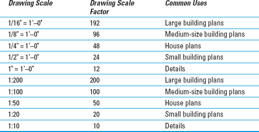
Table 4-1 lists some common architectural drawing scales, using both imperial and metric systems of measure. The table also lists the drawing scale factor corresponding to each drawing scale and the common uses for each scale. If you work in industries other than those listed here, ask drafters or coworkers what the common drawing scales are and for what kinds of drawings they're used.
Table 4-1 Common Architectural Drawing Scales
After you choose a drawing scale, engrave the corresponding drawing scale factor on your desk, write it on your hand (don't mix those two up, okay?), and put it on a sticky note on your monitor. You need to know the drawing scale factor for many drawing tasks, as well as for some plotting. You should be able to recite the drawing scale factor of any drawing you're working on in AutoCAD without even thinking about it.
Even if you're going to use the Plot dialog box's Fit to Paper option (rather than a specific scale factor) to plot the drawing, you still need to choose a scale to make the non-real things (such as text, dash-dot linetypes, hatch patterns, and so on) appear at a useful size. Choose a scale that's in the neighborhood of the Fit to Paper plotting factor, which AutoCAD displays in the Plot Scale area of the Plot dialog box. For example, if you determine that you need to squeeze your drawing down about 90 times to fit on the desired sheet size, choose a drawing scale of 1/8 inch = 1′–0″ (drawing scale factor = 96) if you're using architectural units or 1:100 (drawing scale factor = 100) for other kinds of units.
Thinking about paper
With knowledge of your industry's common drawing scales, you can choose a provisional scale based on what you're depicting. But you won't know for sure whether that scale works until you compare it with the size of the paper that you want to use for plotting your drawing. Here again, most industries use a small range of standard sheet sizes. Three common sets of sizes exist, as shown in Figure 4-2 and Table 4-2:
- ANSI (American National Standards Institute)
- Architectural
- ISO (International Organization for Standardization)

Figure 4-2: Relationships among standard paper sizes.
Table 4-2 Common Plot Sheet Sizes

You select a particular set of sheet sizes based on the common practices in your industry. You then narrow down your choice based on the area required by what you're going to draw. For example, most imperial-units architectural plans are plotted on Architectural or ANSI D- or E-size sheets, and most metric architectural plans go on ISO A1 or A0 sheets.
If you know the desired sheet size and drawing scale factor, you can calculate the available drawing area easily. Simply multiply each of the sheet's dimensions by the drawing scale factor. For example, if you choose an 11-×-17-inch sheet and a drawing scale factor of 96 (corresponding to a plot scale of 1/8″ = 1′–0″), you multiply 17 times 96 and 11 times 96 to get an available drawing area of 1,632 inches × 1,056 inches (or 136 feet × 88 feet). If your sheet size is in inches but your drawing scale is in millimeters, you need to multiply by an additional 25.4 to convert from inches to millimeters. For example, with an 11-×-17-inch sheet and a scale of 1:200 (drawing scale factor = 200), you multiply 17 times 200 times 25.4 and 11 times 200 times 25.4 to get 86,360 × 55,880 mm or 86.36 × 55.88 m — not quite big enough for a football field (American or European football).
Conversely, if you know the sheet size that you're going to use and the real-world size of what you're going to draw, and you want to find out the largest plot scale you can use, you have to divide, not multiply. Divide the needed real-world drawing area's length and width by the sheet's dimensions. Take the larger number — either the length result or the width result — and round up to the nearest real drawing scale factor (that is, one that's commonly used in your industry). For example, suppose you want to draw a 60-×-40-foot (or 720-×-480-inch) floor plan and print it on 11-×-17-inch paper. You divide 720 by 17 and 480 by 11 to get 42.35 and 43.64, respectively. The larger number, 43.64, corresponds in this example to the short dimension of the house and the paper. The nearest larger common architectural drawing scale factor is 48 (corresponding to 1/4″ = 1′–0″), which leaves a little room for the plotting margin and title block.
The Cheat Sheet at this book's companion Web site (www.dummies.com/cheatsheet/autocad2012) includes two tables that list the available drawing areas for a range of sheet sizes and drawing scales. Those tables can help you decide on an appropriate paper size and drawing scale; revert to the calculation method for situations that the tables don't cover. If you don't keep a favorite old calculator on your physical desktop, don't despair: AutoCAD 2012 has one lurking on the Ribbon. You'll find it on the Home tab's Utilities panel (hint: It looks like a calculator). You speed demons can toggle QuickCalc off and on with the Ctrl+8 key combo!
When you select a sheet size and drawing scale, always leave some extra room for the following two reasons:
- Margin allowance: Most plotters and printers can't print all the way to the edge of the sheet — they require a small margin. For example, my trusty old Hewlett-Packard LaserJet 4050 has a printable area of about 8.0 × 10.7 inches on an 8.5 × 11-inch ANSI A-size (letter-size) sheet. (You can find this information in the Plot dialog box, as described in Chapter 16.) If you're a stickler for precision, you can use the printable area instead of the physical sheet area in the calculations described earlier in this section.
- Annotations: Most drawings require some annotations — text, dimensions, grid bubbles, and so on — outside the objects you're drawing, plus a title block surrounding the objects and annotations. If you don't leave some room for the annotations and title block, you'll end up having to cram things together too much or change to a different sheet size. Either way, you'll be slowed down later in the project, when you can least afford it.
Some industries deal with the sheet-is-too-small/drawing-scale-is-too-large problem by breaking up drawings onto multiple plotted sheets. You might consider doing the same.
Don't be afraid to start with real paper. Experienced drafters often make a quick, throwaway pencil-and-paper sketch indicating the dimensions of the sheet of paper they intend to plot on, a sketch of the title block, and a very rough, schematic sketch of the thing they're going to draw. By sketching on paper first, you'll often catch scale or sheet-size problems before you set up a drawing, when repairs take only a few minutes — not after you've created the drawing, when fixing the problem can take hours.
Defending your border
The next decision to make is what kind of border your drawing needs. The options include a full-blown title block, a simple rectangle, or nothing at all around your drawing. If you need a title block, do you have one, can you borrow an existing one, or will you need to draw one from scratch? Although you can draw title block geometry in an individual drawing, you'll save time by reusing the same title block for multiple drawings. Your company may already have a standard title-block drawing ready to use, or someone else who's working on your project may have created one for the project.
The most efficient way of creating a title block is as a separate DWG file, drawn at its normal plotted size (for example, 36 inches long by 24 inches high for an architectural D-size title block, or 841 mm long by 594 mm high for an ISO A1-size version). You then insert or xref the title block drawing into each sheet drawing. I explain inserting drawings into other drawings, or attaching drawings as external reference files in Chapters 17 and 18.