
Drawing a (Base) Plate
With a properly set-up drawing, you're ready to draw some objects. In this example, you use the RECTANG command to draw a steel base plate and column, the CIRCLE command to draw an anchor bolt, and the POLYGON command to draw a hexagonal nut. (Both the RECTANG and POLYGON commands create polylines — objects that contain a series of straight-line segments and/or arc segments.) I describe these drawing commands in more detail in Chapters 8 and 9.
AutoCAD, like most CAD programs, uses layers as an organizing principle for all the objects that you draw. Chapter 6 describes layers and other object properties in detail. In this example, you create separate layers for the base plate, column, anchor bolts, and nuts. This might seem like layer madness, but when you're doing complex drawings, you need to use a lot of layers just to keep things organized.
Drawing rectangles on the right layers
The following steps demonstrate how to create and use layers, as well as how to draw rectangles. You also see how to apply fillets to objects and offset them. (Chapter 6 describes layers in detail, and Chapter 8 covers the RECTANG command. Chapter 11 explains the FILLET and OFFSET commands.) Start by creating a Column layer and a Plate layer and then drawing a rectangular column on the Column layer and a square base plate on the Plate layer:
- Make sure that you complete the drawing set up in the previous section of this chapter and have the drawing open in AutoCAD.
- Click the Home tab on the Ribbon.
You'll find the most frequently used commands for 2D drafting tasks on the Ribbon's Home tab. (For a refresher on the contents of the other tabs, refer to the “Unraveling the Ribbon” section in Chapter 2.) Unless I direct you otherwise, look on the Home tab for the panels and buttons I specify in the following steps.
- On the Layers panel, click the Layer Properties button.
The Layer Properties button is at the upper-left corner of the Layers panel. The LAYER command starts, and AutoCAD displays the Layer Properties Manager palette.
- Click the New Layer button.
AutoCAD adds a new layer to the list and gives it the default name Layer1 (see Figure 3-4).

- Type a more suitable name for the layer on which you'll draw the column and press Enter.
For this example, type Column.
- Click the color swatch or name (white) in the Column layer row.
The Select Color dialog box appears (see Figure 3-5).

Figure 3-5: Blue is the color — select it from the standard color tiles.
- Click color 5 (blue) in the single, separate row to the left of the ByLayer and ByBlock buttons, then click OK.
The Select Color dialog box closes, and AutoCAD changes the color of the Column layer to blue.
- With the Layer Properties Manager still open, repeat Steps 4 through 7 to create a new layer named Plate and set its color to 4 (cyan).
- With layer Plate still highlighted, click the Set Current button (the green check mark).
Plate becomes the current layer, and everything you draw is placed on that layer until you set a different layer current.
- Click Close (the “X” at the top-left corner of the palette in Figure 3-4) to close the Layer Properties Manager palette.
The Layer drop-down list on the Home tab's Layers panel displays Plate as the current layer. Now you can draw a rectangular plate on the Plate layer.
You probably already know that the RECTANG command will draw a rectangular plate for you, but for the next step, pretend you don't.
 You can start from this point with drawing afd03a-i.dwg [afd03a-m.dwg] available in the afd03.zip download at www.dummies.com/go/autocad2012.
 - Click the Application button, click inside the Search edit box at the top of the Application Menu, and start typing RECT…
As you type into the Search box, AutoCAD guesses what you might be looking for. When you've typed enough letters, the command you're probably looking for appears at or near the top of the Application Menu.
- When “Rectangle” appears in the Search results, simply click the command item.
The RECTANG command starts, and AutoCAD prompts you to specify the first corner point. The command line shows
Specify first corner point or [Chamfer/Elevation/Fillet/ Thickness/Width]: - Click in the drawing area at the point 32,7 [800,175].
By watching the coordinate display on the Dynamic Input tooltip, you can see the coordinates of the current crosshairs location. Because Snap Mode is set to 0.5 [10] units, you can land right on the point 32,7 [800,175]. Picking the first corner in this location gives you enough room to work.
AutoCAD prompts at the command line
Specify other corner point or [Area/Dimensions/Rotation]:
- Type 36,36 [900,900] (without any spaces) and press Enter.
Make sure that the Dynamic Input button is on for this step. If it's not, AutoCAD treats an input of 36,36 as absolute coordinates — that is, 36 units above and 36 units to the right of the origin. When Dynamic Input is on, an input of 36,36 is treated as 36 units above and 36 units to the right of the last point — in other words, as relative to the last point. See Chapter 7 for more information about typing absolute and relative coordinates.
AutoCAD draws the 36 × 36 [900 × 900] rectangle, as shown in Figure 3-6. It's on the Plate layer and inherits that layer's cyan color.
You draw the column next, but first you have to change layers.

- On the Layers panel of the Home tab, click the Layer drop-down list to display the list of layers. Click Column to set it as the current layer.
Using the Layer drop-down list saves you from having to open the Layer Properties Manager, select the layer, and click the Set Current button. Becoming an AutoCAD master is all about efficiency!
- Right-click in an empty area of the screen to display the shortcut menu. Choose Repeat RECTANG to draw another rectangle.
In the next steps, you create a hollow steel column.
- At the Specify First Corner Point prompt, type 44,16 [1100,400] and press Enter.
- At the Specify Other Corner Point prompt, type 12,18 [300,450] and press Enter.
A second rectangle is drawn in the middle of the base plate.
Next, you round the corners of the column with the FILLET command and then use OFFSET to give it some thickness.
- On the Home tab's Modify panel, click the Fillet button.
The FILLET command starts, and AutoCAD prompts you to select the first object. Look at the command line to see the options for this command. In the next step, you specify a 2-inch [50 mm] radius fillet to all four corners.
- Type R and press Enter to set a new fillet radius. Type 2 [50] and press Enter.
AutoCAD again prompts you to select the first object. You could pick each of the lines at each corner that need to be filleted (that's eight picks), but because the column is a continuous polyline, in this case a more efficient method is to use the FILLET command's Polyline option to fillet all four corners in one fell swoop.
- Type P to choose the Polyline option, and then press Enter.
AutoCAD prompts you to select a 2D polyline. As you move your mouse pointer over the rectangle, AutoCAD shows you a preview of what the fillet will look like.
- Select the rectangle you drew in Steps 16 to 18.
All four corners of the column are rounded with a 2-inch [50-mm] radius fillet.
Next, offset the polyline to create a 3/4-inch [19 mm] thick steel column.
- On the Modify panel, click the Offset button.
- At the Specify Offset Distance prompt, type .75 [19] and press Enter.
- At the Select Object to Offset prompt, click the rounded rectangle. At the Specify Point on Side to Offset prompt, click anywhere inside the rounded rectangle. Press Enter to complete the command.
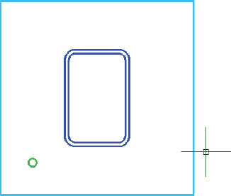
AutoCAD offsets the selected object toward the inside of the rounded rectangle (see Figure 3-7).
 Make sure your Object Snap status bar button is toggled off for this step, or AutoCAD may offset your object back on top of itself.
 - Click the Dynamic Input button on the status bar so the button looks dimmed.
 Now that you've given Dynamic Input a test drive, turn it off for the rest of this chapter. You know how to turn it off and on, and if you like it, by all means, turn it on again for the remainder of the book. Personally, I think that it gets in the way too much to be truly useful, so I rarely use it.
 - Press Ctrl+S to save the drawing.
AutoCAD saves the drawing and renames the previously saved version drawingname.bak — for example, My Plate is Base.bak. .bak is AutoCAD's extension for a backup file.

Figure 3-7: Give it some thickness with OFFSET.
Circling your plate
You can use the CIRCLE command to draw a 1½-inch diameter anchor bolt on an Anchor Bolts layer by following these steps:
- Repeat Steps 2 through 7 in the previous section to create a new layer for the anchor bolts. Give the layer the name Anchor Bolts, assign it the color 3 (green), set it as the current layer, and then close the Layer Properties Manager.
The Layer drop-down on the Layers panel displays Anchor Bolts as the current layer.
- On the Home tab's Draw panel, click the Circle button.
The CIRCLE command starts, and AutoCAD prompts you to specify the center point. The command line shows
Specify center point for circle or [3P/2P/Ttr (tan tan radius)]: - Click in the drawing area at point 38,13 [950,325].
AutoCAD asks you to specify the size of the circle. The command line shows
Specify radius of circle or [Diameter]:
You decide that you want 1½-inch [38 mm] diameter anchor bolts. AutoCAD is asking for a radius. Although you can probably figure out the radius of a 1½-inch [38 mm] diameter circle, specify the Diameter option and let AutoCAD do the hard work.
- Type D and press Enter to select the Diameter option.
AutoCAD prompts you:
Specify diameter of circle:
- Type 1.5 [38] and press Enter.
AutoCAD draws the 1½-inch [38 mm] diameter circle. It's on the Anchor Bolts layer and inherits that layer's green color (see Figure 3-8).
- Press Ctrl+S to save the drawing.
Placing your polygon
Every good bolt deserves a nut. Use the POLYGON command to draw a hexagonal shape on a Nuts layer (well, what else would you call it?). Besides showing you how to draw polygons, these steps introduce you to a couple of AutoCAD's more useful precision techniques: object snaps and Ortho Mode.
- Repeat Steps 2 through 7 in the “Drawing rectangles on the right layers” section, earlier in this chapter, to create a new layer for the nuts and set the new layer current. Give the layer the name Nuts and assign it the color 1 (red).
The Layer drop-down list displays Nuts as the current layer.
You don't have to create a separate layer for every type of object that you draw. For example, you could draw both the anchor bolts and nuts on a layer called Hardware. Layer names and usage depend on industry and office practices, in addition to a certain amount of individual judgment. Having too many layers is better than having too few because lumping two or more layers together is much easier than dividing the objects on one layer into two or more layers.The Ribbon's standard panels aren't big enough to contain a button for every command, so AutoCAD hides the ones that don't fit in drop-down buttons or slideout panels that you open by clicking the panel label. A small down-pointing triangle beside the panel name means there's a slideout with more commands available.
- On the Home tab's Draw panel, click the Polygon button — the one that looks like a plan of the Pentagon.
If this is the first time you've drawn a polygon, its button is hiding under the Rectangle tool button. Look for the button showing a rectangle with little circles at two corners. Click the down arrow beside that button, and then click Polygon.
The POLYGON command starts, and AutoCAD prompts you as follows:
Enter number of sides <4>:
Peek ahead to Figure 3-9 to get an idea of how the nut will look after you draw it. Four-sided nuts can be a little difficult to adjust in the real world, so I stick with the conventional hexagonal sort.
- Type 6 and press Enter.
AutoCAD next prompts you for the center of the polygon:
Specify center of polygon or [Edge]:
In the next steps, you use one of AutoCAD's precision drafting modes: Object Snap. I explain object snaps in detail in Chapter 7, but for now, just follow along here.
- Click the Object Snap button on the status bar to turn on Object Snap mode. When Object Snap is enabled, the button appears light blue and the command prompt shows <Osnap on>.
As you move the crosshairs around near the anchor bolt, notice that AutoCAD tends to pull the crosshairs to certain points on existing objects.
- Move the crosshairs over the anchor bolt you just drew.
A tooltip should show Center and pull the crosshairs to the center of the anchor-bolt circle. If you don't see a Center object snap marker or tooltip, then right-click the Object Snap button and click Center. You may also see tracking vectors across the screen from this point — you can ignore those.
- Click when the tooltip reads Center — not Center-Intersection or something similar — just Center.
The POLYGON command draws regular closed polygons based on an imaginary circle; the center of this imaginary circle is the point you just picked.
AutoCAD prompts you:
Enter an option [Inscribed in circle/Circumscribed about circle] <I>:
- Press Enter to accept the default Inscribed in Circle option.
 The Inscribed option draws a polygon whose corners touch the circumference of the imaginary circle. The Circumscribed option draws a polygon whose sides are tangent to the circumference of the circle.
AutoCAD then asks you to
Specify radius of circle:
- Turn on Ortho Mode by clicking the Ortho Mode button on the status bar until you see <Ortho on> on the command line.
Ortho mode forces the crosshairs to move orthogonally — that is, in a precise horizontal or vertical direction. (I describe Ortho mode more fully in Chapter 7.)
- Move the mouse pointer to the right so the top and bottom sides of the polygon are horizontal, but don't click yet!
- Type 1.5 [38] and press Enter.
AutoCAD draws the nut, as shown in Figure 3-9. It's on the Nuts layer and inherits that layer's red color.
The drawing afd03b-i.dwg [afd03b-m.dwg] contained in the afd03.zip download includes the base plate, column, and one anchor bolt.If your nut-and-bolt looks just like Figure 3-9, way to go — you did it right! If, by chance, your bolt is completely inside the circle, you probably missed Step 4 of the “Circling your plate” section, earlier in this chapter, where I tell you to use the CIRCLE command's Diameter option.

- Turn off Ortho mode and object snap by clicking the Ortho Mode and Object Snap buttons on the status bar until they look dimmed and you see <Ortho off> and <Osnap off> on the command line.
Occasionally, Ortho Mode and object snaps interfere with drafting in AutoCAD. Disabling them (as you do in this step) keeps them from being a problem.
- Press Ctrl+S to save the drawing.
Not much of a base plate yet, is it? But don't worry — I cover creating more nuts and bolts with editing commands in the section “Modifying to Make It Merrier,” later in this chapter. If your brain is feeling full, now is a good time to take a break and go look out the window. If you exit AutoCAD, just restart the program and reopen your drawing when you're ready to continue.