
Chapter 23
The Direct-to-Disk Nagra V (Digital)
The three most important things I want to know when I consider a recording tool:
1. How much engineering experience does the manufacturer have in the field of production sound?
2. How sturdy is the unit? The last thing I want is a unit that appears to work fine in a controlled studio environment but cannot stand up to the rigors of on-location temperature and humidity shifts. Is the device truly portable, or is it bound to a sound cart with a bunch of other gear it needs to make it operate?
3. Electrical power to run the recording device. I am out in “Poe-dunk-nowhere” and the special dedicated rechargeable batteries that came with the unit are down. I need power and I need it now. I have no access to an AC outlet and I have to function—no excuses. The lonely gas station just down the road does have D-cell batteries. Will the recording unit I am considering run on common D-cell power?
THE NAGRA V
Engineering Experience
Stephan Kudelski's 60 years of audio engineering experience has brought forth several of the world's premier field sound recorders for film and television production. And, as in any field of discipline, decades of experience are a priceless commodity.
Sturdiness
Nagras have a reputation for being able to take a great deal of punishment, both in transportability and vibration, field temperature and humidity conditions, as well as plain abuse. Many recorders work fine in the showroom or controlled studio environment, but are just not engineered to handle the demands and hardships of location sound work. This, of course, has been where the Nagra machines have excelled.
Electrical Power
Like its cousins, the analog Nagras, the Nagra V can operate on eight D-cell batteries, available everywhere in the world (using the NA-BB8B #70 1911 000 unit). It can also run off of an AC power outlet. In addition, it can operate using a lithium ion pack (NV-LISET #2098260000) which yields 65 W of power. The recharge time is 7 hours. Remember that lithium ion cells do not like to be charged as rapidly as nickel cadmium cells. If you use the battery charger to run the machine from an AC source, the battery pack can also recharge simultaneously.
Warranty
One of the more interesting attractions to the Nagra V is the new warranty policy. In the past Nagra had a 1-year warranty on their equipment, but now, with their new direct-to-disk digital recorder, the manufacturer is so confident of it that they are including a 3-year warranty with the Nagra V. This, of course, is quite an attraction to the user/owner.
Input Capabilities
The Nagra V is capable of four analog inputs, two using the traditional XLR microphone input connectors and being controlled by the (1) left and (2) right potentiometers on the front panel in classic Nagra protocol. Using the AUX In & Line Out potentiometer (and the menu mode set to AUX In), two additional Line Input signals (such as radio mikes) can be serviced using a 15-pin D-type connector using the extension pin socket on the left Input side panel.
DIRECT-TO-DISK RECORDING
In today's highly accelerated demanding world of postproduction schedules and shortcuts, the Nagra V sets out to service the key issues of being able to record direct-to-disk (D-to-D) in an audio file format that is universally suited for the sample rates and bit depths for today's recording expectations as well as delivering the high standards of recording quality that Nagras are famous for. A WAV (broadcast wave) audio file will be created as it records either at 44.1 or 48 kHz. Using the NV-HSF (high sampling frequency) option, you can record at either 88.2 or 96 kHz sampling rate. The Nagra V also offers both the 16- and 24-bit depths.
One can see the classic Nagra organization protocol of controls and flow in these sleek, efficient units. With very few exceptions, those who have enjoyed the use of the analog Nagra units will find that working with the Nagra V is like slipping on an old comfortable pair of shoes—you feel right at home.
Note the hard-drive enclosure. As of this writing, Nagra is offering a 20 and 40 gigabit removable hard drive. These drives are G-force rated so that you need not be concerned about carrying the unit around while you are recording.
The left Input side panel of the Nagra V offers both traditional microphone (XLR) as well as a 15-pin extension connector for supplemental signal needs.
As with the traditional analog Nagra IV, the Nagra V offers two XLR inputs with a simplified microphone powering selector. The sensitivity of the microphone inputs is selected on the front panel of the Nagra V, but the microphone powering choices are just above the XLR inputs.
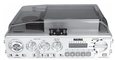
Figure 23.1 Front view of the Nagra V. (Photo courtesy of Glen Trew of Trew Audio, Nashville.)
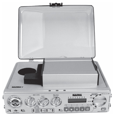
Figure 23.2 Front view with lid up—note the removable Orb drive for direct-to-disk digital recording. (Photo courtesy of Glen Trew of Trew Audio, Nashville.)
+12 V T power
Dynamic
Phantom +48 V
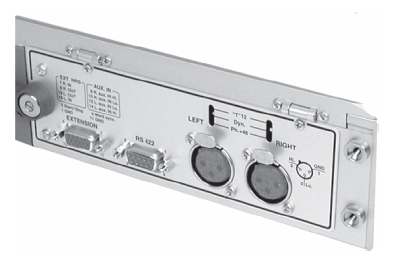
Figure 23.3 View of the left side inputs. (Photo courtesy of Glen Trew of Trew Audio, Nashville.)
A 15-pin D-type connector is positioned at the lower left side of the Input panel. This input socket serves several purposes. It has a symmetrical transformerless Line Input (AUX). If you are using an outboard mixer, you would send your Line Out signal to this connector. You can also send a digital audio input using the AES input cable (#P/N 7031 140 000) that is required. Should you wish to use a noise reduction system, the In/Out access is also served by the 15-pin extension. Here is the correct pinning of the connector.
| Pin # | Connection |
| 1 | Ground |
| 2 | Not presently used |
| 3 | Not presently used |
| 4 | Not presently used |
| 5 | Start/Stop—connect this pin to ground to stop |
| 6 | Digital input (AES bus using a special cable P/N #7031 140 000 is required) |
| 7 | External NRS—Right channel In |
| 8 | AUX In—Right channel High |
| 9 | External NRS—Right channel Out |
| 10 | AUX In—Right channel Low |
| 11 | Ground |
| 12 | AUX In—Left channel Low |
| 13 | External NRS—Left channel Out |
| 14 | AUX In—Left channel High |
| 15 | External NRS—Left channel In |
There is a 9-pin RS 422 symmetrical serial communication port for connection to the outside world. The factory uses this port to test the Nagra V unit. For remote controlling the Nagra V by a PC or laptop, this same 9-pin connector can be used with Nagra software.

Figure 23.4 View of the right side outputs. (Photo courtesy of Glen Trew of Trew Audio, Nashville.)
The right Output side panel of the Nagra V offers several analog and digital signal send opportunities.
OUTPUTS AND INPUTS
Analog Audio Outputs
Two XLR 3-pin male output connectors are the traditional standard for 2-channel stereo analog outputs.
Digital Audio Outputs
An XLR 3-pin male AES output connector services the digital audio output requirements. The resolution is either 16 or 24 bits, depending on the output settings chosen. This, of course, can be directly connected with any other digital equipment with an AES interface for D-to-D transfer.
Telephone Output
On the left side of the Output panel are three Banana Output connectors. This is the telephone output connection, with a transformer with an output impedance of 600 Ohms from 300 Hz to 5 kHz. This can be used for connecting to a standard switched telephone line. The output level of this connection can be selected in the Tel Level of the menu mode to be either 1.55 or 4.4 V. When in operation, the return feed from the telephone can be heard in the headphones or on the internal loudspeaker.
Headset Output
The Headset Output is a standard ¼″ stereo jack connector. The rotary volume control for the headsets is just to the right of the female connector.
Camera Input Return
This mini-jack connector can receive the audio signal from a video camera to the headphones (or speaker) of the Nagra V. This signal is not recorded on the hard drive, but simply used as a monitoring mechanism.
TIME CODE CONNECTOR
The 5-pin Lemo connector (located just to the right of the AES XLR output) is used for time code input and output. The pin connections correspond to that of the Nagra IV-S (Time Code unit), T-Audio (Time Code), and the Nagra D.
| Pin # | Connection |
| 1 | Ground |
| 2 | Time Code Input |
| 3 | Time Code Output |
The time code system of the Nagra V can be set to record all the currently accepted standard time code frame rates, which are as follows:
24 fps—film applications
25 fps—PAL/SECAM video and film-to-video applications
29.97 fps—NTSC black-and-white television
29.97 fps (drop frame)—NTSC color television
30 fps—film applications (NTSC)
30 fps (drop frame)—film-to-video (NTSC)
In addition, the Nagra V can record any of the frame rates either accelerated or retarded by 0.1 percent in order to deal with all the possible anomalies of the NTSC pull-up or pull-down issues, as follows:
| Frame Rate (−0.1 percent) | Actual Frame Rate | Frame Rate (+0.1 percent) |
| 23.976 | 24 | 24.024 |
| 24.975 | 25 | 25.025 |
| 29.940 | 29.97 | 30 |
| 29.97 | 30 | 30.03 |
These frame rate choices are made in the REF.FREQ menu on the front panel.
It is important to note that when the reference frequency is set to Master +0.1 percent (or -0.1 percent) the Nagra V will speed up (or slow down) when making the recording, that is, the time code and the sampling frequency of the audio. For example, setting the machine to 29.97 at 48 kHz sampling rate and selecting Master + 0.1 percent in the reference frequency menu means that the Nagra V will actually accelerate by 0.1 percent and the result will be 30 frame time code at a sampling frequency of 48.048 kHz. The ± 0.1 percent will be stored in the memory of the Nagra V when the power is turned off and will remain accurate for one week.
Unlike previous time code Nagra recorders that recorded a continuous time code signal, the Nagra V simply records a time stamp at the start of each recording, and according to the selected frame rate and sampling frequency, the time code value of any given point after the stamp is simply calculated by counting the number of samples of the audio file. This time code information is readable by any computer device capable of reading an audio file, which is standard throughout the postproduction industry.
Video Sync In
If the Nagra V is fitted with the Internal Time Code option then this is the connector where a video signal (NTSC, PAL, NTSC B/W, 75 Ohms internally loaded) or an external work clock can be imported. The external sync input is yet another way to synchronize the internal clocks of the Nagra V. The advantage of this 5 V logic input is that it can be used to control the VCXO (voltage-controlled crystal oscillator) from an external source. The input can be 44.1, 48, 88.2, or 96 kHz with a logic voltage level from minimum 0.5 to 5.0 V. This signal can be fed to the machine through the BNC connector.
THE FRONT PANEL
The front panel of the recorder is a classic Nagra layout: the modulometer and sensor metering to the left, volume control potentiometers in the center, the Menu panel and Transport controls to the right.
The Modulometer
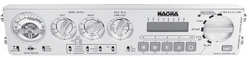
Figure 23.5 Full view of the front panel. (Photo courtesy of Glen Trew of Trew Audio, Nashville).
The Nagra V modulometer uses a single needle, rather than two (one for microphone input 1 and one for microphone input 2) as the analog Nagra IV-S does. Note the two LEDs at either extreme of the scale. The one on the left is marked “L > R” and the one on the right is marked “R > L” which indicate the individual values of their corresponding channels when in 2-channel mode or the highest of the channels when in stereo mode.

Figure 23.6 The modulometer. (Photo courtesy of Glen Trew of Trew Audio, Nashville.)
Note the thick green crescent area just below from -15 dB up to -6 dB. This is the area where the needle will move to when you are in the BATT position (the switch to the lower left under the modulometer). This will indicate the strength of your battery pack.
Remember that this is a digital recorder, so even though at a cursory glance you may mistake this meter as an analog modulometer that you are accustomed to working with on analog Nagras, do not think that you have headroom after 0 as you do on a VU meter. Like a digital peak meter, this modulometer ends at maximum which is 0—there is nothing after it. Your headroom is whatever you consider headroom lower than 0—above what you decide to use as a 0 VU equivalent (such as -18 dB) as we have discussed in previous chapters.
Light/BATT Switch
The little cloud and sunshine icons just above the BATT designation on the lower left switch controls the back lighting of the meter for dark environments or bright situations.
Modulometer Switch
The Modulometer switch directly under the modulometer itself allows you to select whether you want to read Left (channel 1) or Right (channel 2) only. If you leave the switch in the center, or the MAX position, the needle will indicate the highest level obtained between the two channels and the LEDs will indicate which channel this corresponds to. Although it seems a bit odd not to have two needles for two channels, you will actually find it easy to get used to and will actually find it very effective for stereo-level adjustment, especially with the two green LEDs.
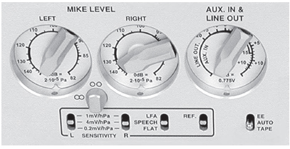
Figure 23.7 The volume controls. (Photo courtesy of Glen Trew of Trew Audio, Nashville.)
Mem/Norm/Reset Switch
The Mem/Norm/Reset switch, to the lower right of the modulometer, controls how you wish the meter to operate. If you leave the switch in the center Norm position, the modulometer will operate in a normal manner, according to the signal (whether input or output). If you flip the selector up to Mem, the needles will indicate the highest obtained level. You can reset the Mem mode by flipping the selector down to Reset. This is a snap-switch position, and can be used at any time without affecting the recording. In stereo operation of the machine the operation of this switch is, of course, linked to the Meter selection switch.
The Potentiometers
The two Mike Level potentiometers are used for precise volume control of the Left (channel 1) and Right (channel 2) microphone inputs (the two analog XLR microphone inputs on the left side Input panel).
Channel Rotary Lock
Note the little stubby stump-like rotary lock seated just between the two Mike Level potentiometers. If the lock is turned upward toward the two small circle icons, it means that each channel can operate independently of each other, working as two separate monaural feeds. If the rotary lock is turned to the left to the 9 o'clock position at the two circle icons that now resemble a figure 8 on its side, this means that the two potentiometers are mechanically locked together, irrespective of their individual positions. To make the rotary lock move into the “interlock” position you must depress it in slightly, and then rotate.
Sensitivity Selectors
The two Sensitivity selectors just below the Rotary Lock are where you select the desired sensitivity for the two microphone inputs. There are three settings:
1 mV/hPa
4 mV/hPa
0.2 mV/hpa
Equalization Selector
Just to the right of the Sensitivity switches is the Equalization selector. The filters available are the same as those on other Nagra recorders and act on both the microphone and Line Inputs.
LFA (Low-Frequency Attenuation)
Speech
Flat
Reference Tone Generator
By pushing this switch upward, the internal reference tone (REF) generator will be activated. As long as the switch is held in the up position, a sine wave of 1 kHz tone will be generated. The reference level is set at the factory at -18 dB. If the Nagra V is in the Test position, the reference line-up tone will be generated and heard as an output only. To record the reference tone, the EE/Auto/Tape selector must be in Auto and the Main function selector must, of course, be in either of the two Record selections.
Auxiliary In and Line Out
The AUX In & Line Out Potentiometer has two different functions, depending on which you make in the menu mode. If the menu is selected to Line Out then the pot will adjust the Line Output level of both channels simultaneously, as well as the headphone and loudspeaker level. Its position is memorized by the microprocessor inside the machine. If you change the menu to use the Potentiometer to control the AUX IN input, then the initial output setting will be stored in the memory of the machine until accessed later. Once the menu is set to the AUX IN mode, then the Potentiometer serves to adjust the level of the Auxiliary Line Input coming from the 15-pin D-type extension connector on the left Input panel of the Nagra V. If you change back to Line Out in the menu mode, the AUX IN level will be stored in the memory until accessed later.
EE/AUTO/TAPE
The EE/AUTO/TAPE selector is situated just below and to the right of the AUX IN and Line Out Potentiometer. With the selector in the EE position, only the input signals will be available at the outputs. (EE stands for electric-electric.)
The Tape position simulates the behavior of a tape transport. The output signal is the recording from the hard drive, like a confidence (playback) head playing what you are recording, not just listening to the input signal. You will also hear the sounds (as like a playback head) when you use the rewind option.

Figure 23.8 The transport controls. (Photo courtesy of Glen Trew of Trew Audio, Nashville.)
The Auto position will automatically select the EE mode or Tape mode, depending on the status of the transport (using the Main function selector).
Note that the CAM. RET (camera return) is selected (via the mini-plug on the right Input panel); the camera return signal will be available for the speaker or headphones only when the EE/AUTO/TAPE selector is in the Tape position. Switching between Tape and Auto position is a fast way to select CAM. RET or Line Out as a monitoring source.
THE TRANSPORT CONTROLS AND MENU PANEL
Main Function Selector
The rotary Main Function selector operates almost exactly like its Nagra IV-S cousin. Let us review each of the positions.
Stop
In this horizontal position the machine is off. Power is now being fed to the electronics of the unit. When you turn the selector to this position, the machine will switch off after a few seconds if the Power Delay Manual (in the menu option) is not set.
Test
When you turn the selector up to Test, all of the electronics are powered up, allowing the adjustment of levels and signal monitoring (just as with the Nagra IV-S). This can be considered as a stand-by for Record mode. All menu verification and settings can be made in this position.
If in the menu, the PREREC is set to On, the record LED will start blinking, meaning that the closed loop recording (a revolving buffer) is activated.
The Nagra V has a prerecord buffer option. You can set the PREREC setting in the menu for as little as 1 second up through a maximum of 20 seconds. This means that if you turned the selector up to Record position, the audio file created would have the previous amount of time (up to 20 seconds) in the audio file before you turned the selector up into the Record mode. This is extremely handy for situations of confusion or hasty started recordings where invaluable material was lost before the recording mixer could get his or her machine into the Record mode.

Figure 23.9 Gray record buttons.

Figure 23.10 Gray play buttons.
Record
When you turn the selector up to the Record position, it sets NO A.L.C./LIM. When you turn the selector up to the NO A.L.C./LIM position, it sets STD. BY.
When you turn the selector down to the STD. BY position, the five gray pushbuttons under the LCD menu display will be activated to work as rewind, fast forward, skip to next cue, and stop, whether moving forward or backward. Should you be in the middle of playing back a cue and suddenly find that the first assistant director has called to roll sound, you can instantly move into Record mode without fear of recording over any audio files because the machine automatically moves to free space on the hard drive.
Play
When you turn the selector down to the Play position, the unit will play back audio files recorded on the removable hard drive. Once the Play mode has been selected the five gray pushbuttons under the LCD menu display become activated.
THE MENU PANEL
The LCD Display
The menu panel is a 14-segment eight-digit backlit LCD display, permitting alphanumeric indications of a large quantity of different information and allowing internal settings of the machine to be made while in the Menu mode. In normal operation it will indicate the current take number and time from the beginning of the recording. It is also used to display the internal status of the machine, as well as the remaining disk space available on the removable hard drive for recording. The display will be illuminated if the Light/BATT switch (just to the lower left of the modulometer) is flipped up to the cloud icon position.
The LCD display can be used to display the following:
Menu Tree
Take Number and Time from start of take
Remaining Time on the removable hard drive (related to bit and sampling rate)
Time Code
Error codes
The flags on the top of the display show:
Video—If a valid video versus time code format is connected.
Tcext—If external time code is present.
Tcint—If during playback the time code is accurate.
Lock—If the machine is locked in Chase mode.
PWER—If the BATT or EXT voltage drops below the limit.
Flag 1—If the Shift button was pressed twice (for menu lock).
Flag 2—Not used as of this writing.
Flag 3—Not used as of this writing.
The Shift Button
The Shift button, located just to the right under the Main function selector, is how you navigate through the various menus on the LCD menu display (under the Nagra emblem). When the Shift button is pressed the five gray transport buttons just below the display will operate, using their shifted arrow features shown above each gray button.
When you take your finger off of the Shift button, the display will return to its main display screen. While you are in the Menu mode, the Stop button (the one with EXE above it) becomes the Execute function.
When the Shift button is pressed rapidly twice, the display will stay in the Menu mode (flag 1 on the display will be on). To remove the Menu mode, press once again on the Shift button or move the Main function selector to another position.
Sync Mode
When the Shift button is pressed and held while moving the Main function selector to the Play position, the machine turns on the Synchronizer.
There are two different modes in which the internal synchronizer can operate. One is called the VAR CLK (variable clock) mode and the other is the FIX CLK (fixed clock) mode.
Fixed Clock
In the FIX CLK mode the machine will always follow the external reference. Once the machine is in the Lock state the internal synchronizer will no longer influence the transport and the playback speed is controlled entirely by the reference frequency (REF FREQ menu). If, however, the synchronizer of the Nagra V sees an error of more than one frame, it will reengage itself to correct the synchronization error. This is the recommended operating mode. In this mode the maximum variation accepted is 100 ppm.
Variable Clock
This mode is designed to allow the machine to follow an external reference that is not the same as the REF FREQ using the internal synchronizer. This setting allows the internal synchronizer to modify the internal clocks in such a way as to follow this REF FREQ (for example, NTSC/NTSC 60). In this mode, the digital output is not available and the quality of the analog outputs may be slightly degraded. In this mode variations of up to ±4 percent in the reference signal will be tolerated.
The Sync mode will turn off when the Main Function selector turned out of the Play mode to any other position.
Power Delay
In the case that the POW. DELAY menu is set to Manual, press and hold the Shift button while turning the Main function selector to the Stop position. Continue to keep the Shift button depressed for an additional 2 seconds until the machine powers off.
Speaker
Selecting On, Off, or Auto for activating the speaker without going into the menus can be made by holding the Shift button in while pushing the Light/BATT switch. Every time this function is executed, it will scroll on the display through the three options.
In/Out Pot
This gives access to the mode of operation of the third potentiometer (AUX IN and Line Out), in case in the menu the line potentiometer of the Nagra V is set to the POT. SHIFT position. That means that the potentiometer will adjust the Input signal if the Shift button is pressed in and held in place and the potentiometer will adjust the Output signal if the Shift button is not being pressed and held in place.
The Nagra V owner's manual has full descriptions and schematics of the various menus.
Once you have wrapped the recording session, you can simply remove the hard drive and either ship it to postproduction editorial or make an archival back-up (e.g., DVD-R) and ship the back-up or ship the original. You will soon develop your own techniques and protocols for what works best for you and your recording project.