
Chapter 22
The Venerable Nagra IV-S (Analog)
I have been pleasantly surprised at the number of e-mails that I have gotten over the last few years, even up to a few days ago, before I updated this chapter from sound craftspeople as well as several directors and producers who have thanked me for including a comprehensive chapter on the Nagra IV-S. Therefore, I have decided not to delete it from this edition. (For information about the digital direct-to-disk Nagra V, see this book's Website at textbooks.elsevier.com/9780240808659.)
THE PRACTICAL NAGRA
The title of this book is the Practical Art of Motion Picture Sound. Practical is a code by which the Nagra operates, as it still remains the highest bang-for-the-buck quality audio recorder available for production sound recording. Trust me when I tell you this, but in the heat of combat, when the production dollars are flowing like a sieve, when the proprietary DAT battery packs have taken a nose dive, when the extremes of high or low temperatures are turning your digital gear into inoperable lock-up, when the moisture of predawn dew or the blistering winds of Death Valley are turning all of your perfect preproduction plans of genius into just the mere desire to survive the day of shooting with any kind of track at all—that is when you stride back to your vehicle and pull out the Nagra. To hell with the producer's or director's craving for techno-fads or the perception of cutting-edge digital promises. You know what the Nagra will deliver under arduous conditions.
Nagras are tough, durable, and extremely forgiving. These remarkable recorders were invented by the Polish audio designer, Stephan Kudelski, and have been manufactured at the Kudelski/Nagra factory in Cheseaux, Switzerland, since the early 1960s. The Nagra audio recorder has attained legendary status, its very name being synonymous with field audio recording for sync sound. Though DAT recorders have come into extremely wide use in the film industry, most of your professional sound mixers keep the Nagra close at hand. Your really good sound mixers use the analog Nagra in concert with digital recording equipment, thereby creating a greater collaborative alliance between the two technologies.
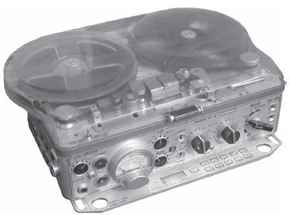
Figure 22.1 Overview of the Nagra IV-S.
Figure 22.1 shows the Nagra IV-S with the 7″-reel expansion and the oversize lid conversion. This allows the use of standard ¼″ stock on 7″ reels with the lid closed. Note that the width of the 7″ reels is wider than the basic Nagra body. Originally the Nagra was designed to use the 5″ reels. Nagra even went on to design an adaptation kit that attaches to the unit with pulley belts so that the sound mixer could use 10″ reels if desired (though this adaptation is seldom used). This particular model also has a slim pull-out time code panel that tucks neatly under the unit between the leg stumps.
There is an interesting rising interest in recording in analog on the Nagra again— no doubt due to comparison test recordings (such as the comparison recording included on the DVD of this book) along with the recording mixer's evaluation of the quality of sound vs. dollars spent. I hear reports of many Nagras being bought on eBay, and even though this is a great way to buy and sell goods directly from others, one should be aware of one very important fact. Nagras were built in two standards, CCIR and NAB.
We all know NAB is the Western standard for calibrations. CCIR is the Eastern European equivalent, and those who do not remember to check whether the Nagra under consideration is NAB or CCIR may discover that they have a beautifully conditioned Nagra that is CCIR instead of NAB.
CCIR models can be converted to NAB by sending it to a qualified tech maintenance service company and authorizing them to make the conversion. The cost of a conversion seems to be hovering around $1,000 (as of this writing) which is not a bad price if you consider the overall value received, as one considers the sale price of a used Nagra IV-S and the workhorse value it will deliver.
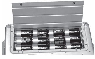
Figure 22.2 D-cell batteries are used in the Nagra IV-S.
You can use a CCIR Nagra perfectly fine if you transfer back from the same machine to whatever source, film mag, or nonlinear digitization or whatever. But you cannot record with a CCIR model and ship the tape to any postproduction facility without conversion to NAB. The truth is, many of the reports are that most of these CCIR units have been maintained in fabulous shape, so, if you find a particularly great bargain on a CCIR unit, you may want to go ahead and acquire it and spend the extra thousand dollars to convert it. That, of course, is a decision you will have to make.
THE BATTERY SUPPLY
One of the best engineering designs of the Nagra is the practicality of power. It does not run on a proprietary battery design, like so many systems today. It runs on the classic D-cell battery, a standard power unit found everywhere. Unlike many new technology devices that work only an hour or two on their special-made batteries, the Nagra can work like a race horse for days on one set of 12 D-cell batteries (Figure 22.2).
When you have checked the strength of your battery supply (as explained later) and have decided to put in a fresh set of D-cells, you need to flip the Power Source selector switch (item 1 in Figure 22.3) to EXT (external). Make sure that the Main function selector bar (item 4 in Figure 22.3) is turned to the OFF position, horizontal, or 9 o'clock position. This will ensure that no power is flowing through the unit. Never, ever change out batteries when the Main Function selector bar is turned up to Test!
Make sure the lid of the unit is secured and carefully turn it over. I like to use a hand towel as a protective surface, no matter where I am recording. On the underside you will see a rectangular stainless steel cover held in place on the back edge by two small stainless steel clips and locked down in front by two quarter-turn screws. Notice that the edge of the screws has a flattened side to them. It is a good idea to carry a coin, as the two lock-down screws of the battery well cover are designed perfectly for a nickel (though any coin will do). Place the coin in the screws and turn until the flattened edge of each screw is aligned with the edge of the battery well housing. Lift the lid up and out and place it to one side.
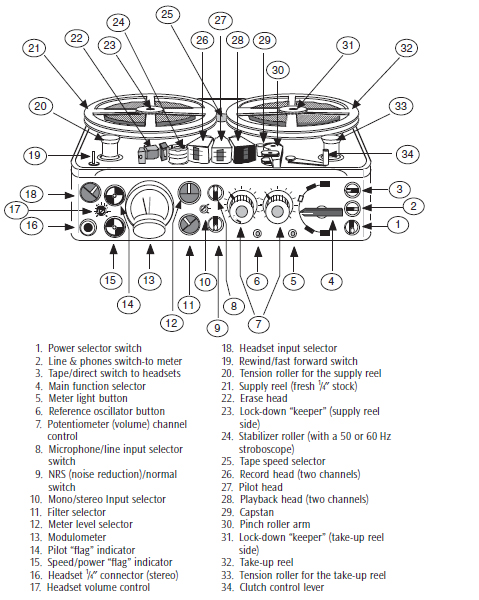
Figure 22.3 Nagra IV-S designation chart.
Always use Duracell batteries. No, I do not own any stock in the company. I give you this advice from years of experience. They are recommended for good reason— they endure. With good operational procedure protocol your fresh change of batteries can last for days, even weeks if you use good power management. I had one set actually last 6 months, but that is extremely rare.
Take a moment to check that the six spring-action contact terminals on the sides of the battery well are clean and free of any battery corrosion or fouling dirt or debris. On earlier Nagra models, the three positive side contact terminals are spring-action fuses. You should take a moment to remove each one and closely inspect it. If they need to be changed out, you need to use 2.5 A 5 × 20 mm replacements. Be careful to insert them correctly or they could burn out. Of course, you will know very quickly that your fuse was replaced improperly when you turn the Nagra over and try to power it up again and nothing happens. Be sure you place the batteries into the trough guides facing the correct direction. If you do not place them all in facing the correct direction the power flow will be wrong.
Once you have properly placed the new batteries in, replace the stainless steel cover and using your coin again, twist the lock screws 90 degrees to secure it in place. Turn the unit over and flip the Power Source selector switch back to BATT (internal batteries). Turn the Main Function selector bar up to Test, thereby powering up the Nagra electronics. Just off center of the Front Control Panel is the Level selector; rotate the selector to BATT. The modulometer needle should flip all the way over to the right side of the meter. If it does not, you need to go back and check your batteries and/or fuses to understand why.
If you use an older Nagra that has a Volt/Cell option on the Level selector you can get an exact measurement of the battery power by turning the Level selector to this option. The modulometer needle should drop back to about midpoint on the meter. A fresh battery should read 1.5 volts or better. As the batteries diminish in strength you will notice that the voltage strength will drop bit by bit. It is unwise to use the batteries if their voltage strength has dropped under 1.2. Time to change them out with a fresh set.
On the Nagra IV-S you do not have a Volt/Cell selection. That function is incorporated in the BATT position and shows up on the modulometer in the short third-level set of numbers to the right side. The same indication of voltage strength applies.
Remember that all batteries, no matter what make or model, are going to suffer in cold conditions, so it is a good idea to keep your batteries in a warm and temperature-protected spot. I always keep a packing blanket as part of my kit to wrap the Nagra, leaving a flap over it for easy access. When I can, I also use two pairs of battery-powered electrical socks (to place under the Nagra) to ensure stable battery power. Go to your favorite sporting goods store and shop as if you were going duck hunting and need to keep warm; you will think of and find a multitude of helpful devices and aids.
THE PARTS
The designation chart (by number) shown in Figure 22.3 will help you through the rest of this chapter because it identifies which part, switch, or selector procedure is being described.
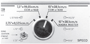
Figure 22.4 The tape speed selector is nestled underneath and between the take-up reels.

Figure 22.5 The tape path: clean and simple.
Speed and Equalization Selector
It is a good idea to decide what tape speed you want to record at before you thread up a fresh roll of stock. It is a pain to get to this selector once you have threaded your tape stock, as you can see in Figure 22.5.
This decision goes back to everything we have discussed throughout this book, so I am not going to belabor that point.
The Nagra records at the following tape speeds:
3¾ ips = 9.525 centimeters per second
7½ ips = 19.05 centimeters per second
15 ips = 38.1 centimeters per second
The Nagra IV-S also has a setting for 15 ips Nagra Master. This setting allows the equalization curve as if you were recording at 7½ ips, giving all the benefits of compensating for a high-frequency loss.
Note the “calibrated” sticker over the bias equalization adjustment, just to the lower left of the Speed selector. Unless you wish to become responsible to be your own audio tech engineer and recalibrate your equipment, you would be wise not to tinker with or try to recalibrate your machine yourself. That kind of work should be handled by a professional audio engineer who does maintenance work on Nagras for a living. Your job is to go out and capture the audio recordings—practice your art form. The audio engineer's job is to maintain your equipment when needed and keep you recording true and clear.
Once you have decided on the tape speed you wish to run at, leave it. It is a really bad idea to change tape speeds during the recording process of a job.
Tape Thread Path
The Nagra has to be the easiest tape path for loading. Open up the head/transport mechanism by grasping the Clutch control lever (item 34 in Figure 22.3) and pulling it outward, toward you. This is a three-position lever. With the Clutch lever pulled all the way out, the head/transport mechanism will open up, allowing a clear path for the ¼” tape stock to run from the far-left tension roller across to the far-right tension roller without obstruction.
Place your fresh roll of ¼″ tape stock on the left transport spindle (item 21 in Figure 22.3) with the fresh roll of tape unwinding counterclockwise. You will see that there are three small stainless steel pins that the ¼″ hub must seat precisely onto for proper stability. Once the reel is seated correctly, screw down the Lock-Down keeper (item 23 in Figure 22.3). Mind that you do not misplace these little elusive jewels, as they are not cheap to replace. A clever trick many mixers use is to slide the two keepers over the upright handle of the Clutch control lever, acting as a hook to keep them from being misplaced until they need to screw them back on to hold the ¼″ reels in place. Now pull the ¼″ tape toward you, pull it around the supply reel Tension roller (item 20 in Figure 22.3), then straight across past the head stack and around the take-up reel Tension roller (item 33 in Figure 22.3). Note that as you pull the tape up and into the take-up reel, you will see a slot to insert the headend of the tape. Be careful not to inadvertently flip the tape stock over as it will cause the tape to wind onto the take-up reel with a half twist. This can be easily loaded incorrectly, so you should try it a few times to get the hang of it.
I personally pull the end of the stock into the slot and then spin the take-up reel three or four turns to hold it in place. I keep either a razor blade or a small pair of scissors in my recording kit, which I use to trim the head end excess flush to the take-up reel hub. The reason you want to do this is when you close the lid of the Nagra and begin recording, you will have no excess ¼″ stock sticking up and scraping the underside of the lid, which can cause unwanted noise. Once you are satisfied with the tape being securely loaded and the excess stock trimmed away, grasp the Clutch control lever (item 33 in Figure 22.3) and push it in toward the Tension roller. The head/transport mechanism will rotate into place, properly pinching the ¼″ tape against the Capstan (item 29 in Figure 22.3) and Pinch roller lever (item 30 in Figure 22.3).
If your Nagra is equipped with a playback shield (which may cover the pilot and playback heads or just the playback head), be sure that it was flipped open when you loaded the tape. Believe it or not, I have seen several rolls of transfers where the mixer was listening directly from microphone and had no idea that he had loaded the tape over the playback shield, therefore causing a misalignment over the record head with poor results.
Once you are satisfied that the tape is loaded correctly, flip your playback shield up into position (if your Nagra is equipped with one). Note the tension rollers when you roll tape (for Record or Playback). They will undulate, wobble back and forth for a brief moment as they bring the feed and take-up transportation of the ¼″ stock past the head stack array and Capstan/Pinch roller. They should settle down quickly. Sometimes they continue to vacillate. Turn your hands over and use your thumb nails to gently drag on the top of them, which should encourage them to stop undulating. Most of the time this will occur during the first rolling of the morning (temperature acclimation stiffness or such; who knows?). You must settle the Tension rollers down or you will suffer major wow-and-flutter as they yank and slack out on the ¼″ tape that is being pulled across the Capstan.
If the Tension rollers continue to be a problem more than once or twice where they tend to undulate even after you attempt to settle them, it means your Nagra probably needs an adjustment by your audio tech contractor. Just to make sure it is not something on the deck that is inhibiting smooth operation, you should keep a can of compressed air in your kit. Using the nozzle extension, place it under the bottom edge of the rollers and give each Tension roller a blast, just to be assured that no foreign matter is causing the excessive undulations that can easily be blown away.
Rewind Switch
Rewinding
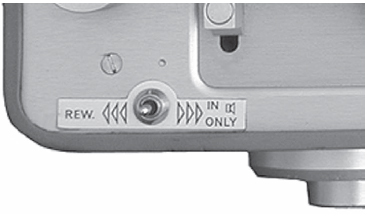
Figure 22.6 The Rewind/Fast Forward switch, located on the upper left-hand edge of the deck.
This is a good time to comment about the rewind and fast forward capabilities of the Nagra (Figure 22.6). If you need to rewind your tape to listen to a previous take you accomplish this maneuver by grasping the Clutch control lever (item 34 in Figure 22.3) and opening up the head/transport mechanism. Turn (item 4 in Figure 22.3) the Main function selector up one click to Test. Turning the Main function selector up to Test powers up the unit, allowing the motors to work in rewind mode if necessary.
It is a good technique not to rewind with the Playback shield in an upright position. Flip the shield back so the ¼″ tape will not rewind against the heads, effectively sandpapering the tape emulsion unnecessarily.
Keep your right index finger in place just to the side of the take-up reel (but not actually touching it) to guard against runaway tape when you stop rewinding. Now click the Rewind/Fast forward switch (item 19 in Figure 22.3) to the left. The Nagra will instantly start rewinding.
Personally, I use my left thumb to guide the rewinding tape in close, but not actually touching the playback head. In this manner I can hear important audio points of reference as the tape rewinds and makes it very easy to rewind virtually exactly where you want to be for playback. When you wish to stop, simply click the Rewind/ Fast Forward switch straight up and the left motor will stop. This is where your right index finger comes in handy as a gentle brake. If you do not encourage the take-up reel (gently) to stop, it will unwind a bunch of recorded tape off the right side of the machine.
Close the Clutch control lever, closing the head/transport mechanism. Flip the Playback shield back up into position. Turn the Main function selector back down to the horizontal position. You can now play back the tape by turning the Main function selector down to either of the two Playback positions.
Fast Forwarding
The Nagra does not fast forward at the speed it can rewind. The idea of fast forward is simply running twice as fast as normal speed. When you have the Nagra in playback mode, you can click the Rewind/Fast Forward switch to the right and the Nagra will accelerate the playback speed. It helps a little bit. You have to understand that the Nagra is not designed for high-speed wind and rewind, but to record at a very high resolution and ship the reels “tails out” to the lab. It is just as simple and as practical as that.
Head Stack and Transport
The head stack is beautifully designed with very easy access to clean the heads. I always take a moment to inspect and clean the head stack before I load another roll of ¼″ tape. Do not use consumer cotton-tipped ear swabs, as they fleece and leave stringy cotton remnants on the heads. (Remember, it takes only the slightest speck of foreign matter to ruin your recording). Try to use a foamed-tip video cleaning swab if you can, but I also find the use of a cotton-tipped cleaning stick, such as the Realistic brand at Radio Shack, to work very well. This cotton tip does not unravel and leave remnants. Use denatured alcohol. If you have to use isopropyl you must wait a few moments for the heads to fully dry out before loading up a fresh roll of stock. Make sure that you clean everything along the tape path. Look for grit and excess magnetic emulsion, an extremely fine dark shedding of the stock from the physical rubbing across the heads.
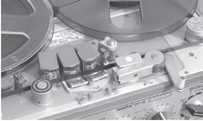
Figure 22.7 Transport assembly in open position.
The degauss Erase head (item 22 in Figure 22.3) is on the far left in Figure 22.7. Do not depend on this head as a bulk degausser; it is meant to erase field-strength. If you are using recycled ¼″ stock (which you should never use for important production dialog), you need to have them bulk degaussed through a heavy-duty magnetic unit prior to going out to record.
The Stabilizer Roller
The Stabilizer roller (item 24 in Figure 22.3) sits right next to the Record head and serves two important functions. First, it guides the ¼″ tape around at the proper angle to seat against the Record head for proper recording, and second, it has an interesting gearlike adornment on top with either a “50” or a “60” (European 50 cycle or American 60 cycle). As the machine is running up to speed you can lean over and look down at this spinning top, and under AC light (burning at either 50 cycle or 60 cycle), squint slightly, and if the machine is running at proper speed, the “gear” will appear to be holding still. If the machine is running fast or slow, the “gear” will appear to drift around. This is an indication that you should have your machine checked.
The Record Head
The Record head (item 26 in Figure 22.3) records 2 channels of analog audio.
The Pilot Head
The Pilot head (item 27 in Figure 22.3) records the sync signal down the center (in between left and right audio channel).
The Playback Head
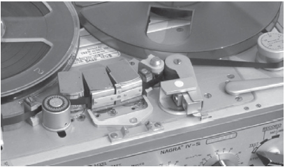
Figure 22.8 Transport assembly in “closed” position.
The Playback head (item 28 in Figure 22.3) plays back the 2 channels of analog audio that is recorded by the Record head. As stated before, most of the more recent machines are equipped with a hinged Playback shield. Note that the photo above (Figure 22.7) has the shield covering both the Pilot and Playback heads. Some machines have Play back shields that only cover the Playback head. These shields help guard against RF radio signal interference.
The Capstan and Pinch Roller
The Capstan (item 29 in Figure 22.3) is extremely important. This little spinning metal post is the precise speed mechanism that literally drags your ¼″ tape across the heads at precisely the right speed. It is dependent on the Pinch roller; when the Clutch control lever is pushed forward into position (as it is in Figure 22.8), the Pinch roller arm is rotated into position, with the Roller (made out of a hard rubber-like synthetic material) perfectly pressing a smooth and even surface firmly against the Capstan. If you do not take great care in the delicate cleaning of this roller, making sure that there is no buildup of oxide, grit, or other foreign matter, the Pinch roller will not properly track the ¼″ tape and it will result in improper tape speed and can cause the tape to “walk” up the Capstan, causing the tape stock to ride out of alignment with the Record, Pilot, and Playback heads. Be extremely careful not to cause any kind of dimple, nick, or scratch on the Pinch roller. It is exactly these kinds of wounds that will lead to catastrophic performance as just described.
On the far right of Figure 22.8, you can see the Clutch control lever (item 34 in Figure 22.3) in the open position. Note the position of the Stabilizer roller (item 24 in Figure 22.3). When the Clutch control lever is pushed in, the Stabilizer roller moves forward, pressing in against the ¼″ tape to make it track in across the Record head at just the right angle. Note the 90-degree rotation of the Pinch roller arm up against the Capstan. When the Nagra is not in motion, the Pinch roller rests slightly relaxed off the tape. It pinches in on the tape stock when in the Record or Playback mode.
Front Control Panel
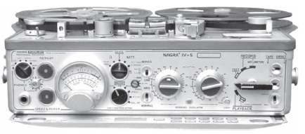
Figure 22.9 Front control panel, full view.
Figure 22.9 shows the full-frontal view of the front control panel. As you come across other Nagra models, you will notice that certain controls and indicators are located differently. Unlike the other versions, the IV-S has its Pilot and Speed/Power flag indicators located to the left side of the modulometer, rather than on the far right, just to the side of the Main function selector bar. Some versions have their Tape/Direct, Line & phones and power switch array to the left of the Main function selector bar, whereas the IV-S has those switches to the right of the Main function selector bar. These differences are strictly cosmetic and have evolved over years of refining the sound mixer's eye-hand coordination efficiency with the machine.
Right Side of Front Control Panel
Power Selector Switch
The Power selector switch is shown as item 1. Since the Nagra can work on an external power converter power pack from an AC outlet, you need to tell the machine whether it is using the AC power pack or internal battery power. Up is AC power pack; down is internal batteries.
Tape/Direct Switch
Put your headsets on and flip the Tape/Direct switch (item 3 in Figure 22.3) to the right (Direct) and you will be listening directly from the microphones. You will need to do this when the ¼″ tape is not in motion in either the Record or Playback mode. When you are monitoring for levels in standby (Test) mode you will only be able to hear in the Direct position.
Once you have engaged the machine to record you will want to flip the Tape/ Direct switch to the left (Tape), so you can hear what you are actually recording. Believe me, there are times, due to oxide build-up, incorrect threading of the machine, or some other problem, you will hear your incoming signal just fine when in Direct mode, but you are not actually recording properly. You will not know this unless you are monitoring in playback mode, with the Tape/Direct switch flipped to Tape position.
Most mixers will flip the switch back and forth during the recording to A-B the signal, in other words, to see if they are getting a true or transparent replication from the microphones onto the tape oxide.
Line & Phones Switch

Figure 22.10 Front control panel, right side.
The Line & Phones switch (item 2 in Figure 22.3) will allow you to A-B compare by use of the meter (item 13 in Figure 22.3, the modulometer). This switch is a momentary contact switch, so when you let go of it, it will automatically return to the Direct position. I personally do not use this option very much, as my ears will tell me so much more about the clarity and coloration of the A-B comparison using the Tape/Direct option instead; but I could see its use if you are doing Line Input line-up tones and want to see how accurately your tape oxide is mirroring the incoming signal.
Main Function Selector Bar
When the Main function selector bar (item 4 in Figure 22.3) is in the horizontal position, as shown in the full view of the Nagra panel (Figure 22.10), all electrical power to the Nagra is turned off. There is no power running through any electronic components and the batteries are not being drained.
Because it takes a few moments for the electronics to warm up to optimum capacity, you never want to just flip the selector bar straight up into a Record mode from the off position. The first few seconds of the recording will sound dreadful—sounding like a breaking-up distorted awakening. This is why recording mixers will anticipate the assistant director's call to make the shot. Most good mixers are already rolling when the AD calls out, “Roll sound”—usually because the mixer is also responsible for sounding the warning bell and turning on the red light. Once the AD calls for “Light and bell,” the mixer usually flips the warning on and rolls the recorder. To anticipate this, the recording mixer gets into a rhythm which starts with knowing when to warm up his Nagra by flipping the Main Function selector bar up to the Test position. In a matter of 4 to 6 seconds, you will hear the signal from your microphones well up and the signal becomes clear. From this moment on you are free and ready to roll sound and record confidently.
Roll to Record
There are two Record positions. The first position records with a limiter. This limiter compresses the volume signal when it peaks too high, thereby guarding against distortion and spiked explosive moments that oversaturate the stock. That is all well and good for documentary and other monitoring missions where you cannot ask for a second take because you peaked out. However, recording with a limiter also means you are going to have an audio track that may (and probably will) have periodic compressed areas that are not at all desirable in a theatrical film. That is why you have the second recording position, the 12 o'clock, straight up position. You will now be recording in the no limiter position, thereby turning off the compressing limiter option. Now you are on your own, but of course that is why you are the recording mixer.
Roll for Playback
To listen to recorded material in a Playback mode is accomplished simply enough by clicking the Main function selector bar downward to either the first or second Playback position. The difference between these two options is that the first position will give you playback signal through the headsets only. It is important to note that the internal resolver (to maintain sync speed) function is turned off during playback in this position.
To play back the audio signal with the internal resolver in an active mode, you need to turn the Main function selector bar down to the second playback position (marked with a double-cone icon). This second position will send the signal to the headsets and also to the built-in speaker that is mounted on the right flank of the unit. This speaker should not be expected to yield full fidelity as you will hear through full-spectrum monitor speakers later, but they are meant to give you a guidance in that what you have done is clear and acceptable sound; or, if you do have distortion issues, to address what you are doing wrong and correct it.
Light Button
Pressing this small button (item 5 in Figure 22.3) will turn on the light in the modulometer so you can read it under poorly lit conditions. This is a momentary button, so when you take your finger off of it the light will shut off. If, on the other hand, you wish to have the light remain on, push and pivot the button to the right. The meter light will remain on until you pivot the button back to the left. Try not to leave the light on too long as it does accelerate the wear and tear on the batteries.
Reference Oscillator Button
Press this momentary contact button (item 6 in Figure 22.3) and the built-in Reference Tone Oscillator will activate. You will want to press and hold this button down for 10 to 20 seconds to lay down the -8 dB reference line-up tone at the head of each roll of tape.
When the mixer ends each recorded take, he or she will press this button twice to leave two short beeps to mark the end of each take. Later in sound transfer, the transfer engineer can spin the tape at high speed, holding his or her thumb against the tape, nudging it partially in toward the playback head (without touching it) and this reference tone signal is strong enough to be heard as fleeting blips going by. The transfer engineer can count those blips flying by as he or she looks at the sound report and counts down (or up, depending on winding direction) to quickly locate the precise take required.
Volume Control “Potentiometers”
These two knobs (item 7 in Figure 22.3) are the volume control pots, or what Nagra likes to call the potentiometers. Channel 1 (left) has a small crescent latch built into it. If you move the latch down you will unlock the two knobs so they can work independently. If you move the latch up, you will lock the two knobs together. In this manner, if you move one, the other will move in precise linked calibration. This is very useful if you wish to have channel 2 (right) record the same incoming signal as channel 1 (known as 2-track mono), but at a lower level (e.g., -10 dB). Unlock the two knobs. Turn them both completely to the left until they are at Off. Now move the crescent lock upward to link the two knobs together.
If you feed an incoming line-up tone into the Nagra from your outboard mixer or from a portable reference generator, you can quickly calibrate an exact -dB setting. Turn channel 1 up until the two needles on the meter (modulometer) reads 0. Obviously channel 2 has come up to the exact same position because the two pots are locked together. Now move the crescent lock-down to unlock the two channels. Move the channel 2 (right) knob to the left until the red needle (channel 2) backs down to the -10 dB position on the meter. Now move the crescent lock up to lock the two volume pots back together again.
Now you have channel 1 and channel 2 locked together in precise relationship with each other, only -10 dB apart. This works wonders when you have sudden volume bursts, such as gunshots, screams, door slams, or other sudden concussionary sounds that will blow out and distort channel 1. Later in the postproduction phase, the dialog editor will take the channel 2 transfer of the blown-out channel 1 performance and integrate it into the dialog (or P-FX track) to utilize the nondistorted version.
Linking the two channels is also mandatory in true stereophonic recordings, where the two channels have to be in precise left-right balance to effectively create the envelope of the audio field presence.
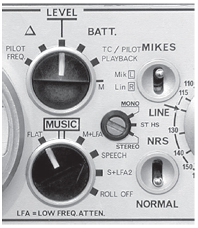
Figure 22.11 Front control panel, center.
Personally I like to simplify the signal path in recording. I feel that the more you run the audio signal through things, the more you are going to add noise and/or hiss. Be careful not to send a weak or artificially lowered signal into your Nagra if you are using an outboard mixer. Beginners often make the mistake of having too low a level feed into the mixer (using the line input mode) which compels them to turn the poten-tiometer volume pots up too high in order to boost the signal. By doing this you will dramatically increase hiss and excessive ground noise rumble. That is why you want reference tones and known levels that can be read on meters and matched accordingly. If you are having to turn your volume controls over past the 2 o'clock position you are risking unwanted hiss and noise—so beware.
Center Controls of Front Control Panel
The Meter Selector
The Meter selector (item 12 in Figure 22.3) tells the meter (modulometer) (item 13 in Figure 22.3) what it is you wish to view. This selector is your gateway to check the performance of the machine and/or incoming or outgoing signals as read on the meter. Different models of Nagras have different variations on possibilities to meter. Some Nagras have options to measure Compression, Volt/Cell, and Bias, for instance. The Nagra IV-S shown here has been greatly simplified, excluding the need for some settings found on older models.
Pilot Frequency
This setting is used in conjunction with the built-in QFMS frequency meter, between the pilot signal—recorded or played back on the pilot track and a 50 or 60 Hz internal reference. The red needle may deviate as much as plus or minus 4 percent as it compares the pilot signal versus a 60 Hz crystal. The green needle will show on the dB scale the signal from the channel with the greatest amplitude.
This setting measures on a 0 to 100 percent scale; groove depth of a record made from recorded signals in accordance with NAB weighting; 100 percent corresponding to a 50 μm vertical deviation of the cutting stylus. The green needle, as with the Pilot Frequency setting, will show on the dB scale the signal from the channel with the greatest amplitude.
Level
This straight up position will allow you to monitor the two audio input levels of channels 1 (left) and 2 (right). Note the top dB scale on the modulometer (see Figure 22.12 in the next section). The modulometer is a peak meter. Unlike its cousin the VU meter, which shows an averaging of the signal, a peak meter shows the exact peaks of the loudest amplitude of the signal. It is important to know that 8 dB on the Nagra's modulometer equals 0 level on a VU meter. The 0 level shown on the modulometer is, therefore, 8 dB hotter than on other tape recorders using the standard VU meter system.
With this in mind, your normal dialog recording should be bouncing around -5 to -10 dB (or around the straight-up area on the meter). This gives you a nice amount of head room for loud sudden sounds, such as screams, door slams, crashes, and impacts, etc. If your dialog is recording as high as 0 dB on the modulometer, it will be far too hot when you transfer to the audio signal to another medium, for that would be equivalent to a +8 to +10 dB peak which is really hot!
You should reserve the need to record above 0 dB for exceptional situations, such as momentary sounds (e.g., gunshots or door slam-type sounds), and only momentary.
Battery
Flip the selector to the BATT position and you will be able to see how your batteries are doing. This is your Battery reserve level and is read on the bottom scale, the short one on the right side of the modulometer window. Remember, as discussed earlier under The Battery Supply, a fresh battery array will read 1.5 volts or better. As the power drops down close to 1.2 volts it is time to change out to a fresh set.
TC/Pilot Playback
This selection will measure the sync signal on the tape. The strength will be read on the center scale (with Pilot above it) of the modulometer window. The red needle will read -4 to +4 percent on the scale, the frequency shift between the pilot signal recorded or played back on the pilot track and a 50 or 60 Hz internal reference. The green needle will read on the 0 to 100 percent scale, the level of the signals recorded or played back on the pilot track; 100 percent corresponds to a frequency deviation of ±40 percent. This setting is used more often by your tech maintenance person when your Nagra goes into the shop for its checkup.
M Setting
This setting will read the current through the motor. The red needle will read on the 0 to 100 percent scale; 100 percent corresponding to 250 mA.
Filter Selector
The Filter selector (item 11 in Figure 22.3) is where you choose what kind of frequency attenuation you wish to record. On the Nagra IV-S most mixers will record at either flat (which is most of the time), or for exterior work they find a need to flip the Filter selector down to S + LFA2 (Speech plus Low Frequency Attenuation 2). This will help with some wind noise and low-end rumble issues. With today's microphone wind abatement technologies, there is little need to have to resort to the second setting unless you hear a great deal of low-end rumble. When in doubt, record flat. Postproduction may very well want the low-end frequencies that you rolled out of a recording. They can always remove it later; they cannot reinstate it naturally if you canceled it out of the equation.
Flat: Linear response curve.
Music: High-pass filter, -3 dB at 40 Hz.
M + LFA: Music and low frequency attenuation, -7 dB at 40 Hz and -3 dB at 400 Hz.
Speech: High-pass speech filter, -3 dB at 80 Hz.
S + LFA2: Speech filter and low-frequency attenuation, -7.5 dB at 80 Hz and -3 dB at 400 Hz.
Roll off: Strong low-frequency attenuation, -10 dB at 100 Hz and -3 dB at 400 Hz.
Note: Most older Nagras may show these filter settings as LFA1, LFA2, FLAT, HP1,
HP1 + LFA1, and HP2 (High Pass). Those Nagras that have LFA1 and LFA2 offer two roll-off variations. You need to listen through your headphones to the subtle differences and decide what feels best for your needs. Most mixers use two basic settings—flat for interior work and HP1 + LFA1 (denoted with a box around it) for exterior work. These two settings will usually achieve a consistent response for your production track throughout the shoot.
Mikes/Line Selector Switch
The Mikes/Line selector switch is shown as item 8 in Figure 22.3. If you are recording with microphones, you will obviously switch it up to Mikes. If you are recording with an outboard mixer or making a machine-to-machine transfer, you will need to flip this switch down to the Line position. Remember that you do not plug line inputs into the XLR inputs on the left flank side of the Nagra. To do so will cause you to double-phantom your microphones, as your outboard mixing panel is sending a phantom power signal and by going through the microphone XLR inputs of the Nagra defaults through the phantom power supply, causing a distorted signal. This will be covered later when we talk about the Tuchel In & Out connectors and XLR Microphone Inputs.
Noise Reduction Switch
If you intend to utilize the internal noise reduction system (item 9) or if you intend to utilize an outboard noise reduction system (by coming into the left flank Tuchel connector marked EXT.NRS) you need to flip the switch up to NRS. If you do not want to use NRS simply flip the switch down to the Normal position.
Mono-Stereo Selector
Set the Mono-Stereo selector (item 10 in Figure 22.3) in the configuration that you wish to import your signal. In the Mono mode the 2 coupled inputs are connected to the 2 channels. In the Stereo mode each input is connected to the corresponding channel for dedicated control. In the ST.HS (Stereo High Sensitivity) mode each input is connected to the corresponding channel as in the Stereo mode, but the sensitivity of the input signal is +6 dB higher. This gives you a little extra firepower if you need it without cranking the Volume Control Potentiometers up too high and building up unwanted bias floor hiss. Of course it will add a little more extra bias hiss. More volume cannot help but do that, but it is better than just cranking up the volume controls to maximum. This is especially useful for subtle stereophonic backgrounds and nonclose proximity audio events.
Left Side of Front Control Panel
Headphone Jack and Headphone Controls
The lower left corner of the Nagra has a ¼″ stereo jack for your headsets. Just above it and to the right is the volume control setting. You simply turn the flat-edged screw using the 0 to 7 level calibration. Older Nagra models have the volume control located just below and to the right of the plug input, right next to the modulometer. Other Nagra models use the upper left-hand corner selector switch as a volume control selector with a 0 to 5 level setting.
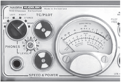
Figure 22.12 Front control panel, left side.
In the model shown in Figure 22.12, the upper-left selector is the Headset input selector. You can turn your headsets off by clicking the selector all the way to the left. Click it to the right one stop for the Cue option. Click it one more stop to the right to hear the left channel only. Click it one more stop to the right to listen to right channel only. Click it one more stop to the right to listen to full Stereo. If you wish to listen in flat monaural through both ears, click the selector to the far right to Mono.
If you are recording Stereo or two separate microphones as monaural feeds and are concerned about phasing issues, you can click the selector to the right to the Mono position and the two channels will be folded down together. If you have phasing issues you will immediately experience a fully swimming quality to the signal and you will immediately know that you need to make an adjustment. Some Nagra models have been outfitted with a very convenient momentary contact switch. You merely press it and both channels automatically fold down so that you can easily A-B compare between discrete 2 channel and folded mono. Both procedures accomplish the same result ultimately.
Pilot Flag Indicator
The Pilot flag (item 14 in Figure 22.3) shows completely black when the unit is at rest. When you roll in the Record mode, two little white flags will flip open and hold steady when it reads the incoming sync signal. As you record these two flags hold perfectly still until you shut down. If they flicker, it means you are getting a bad sync signal and you will probably not be able to warrant good lip sync. If you are using an external sync source, check the jumper cable for it might be loose or the contact is not clean.
Speed and Power Indicator
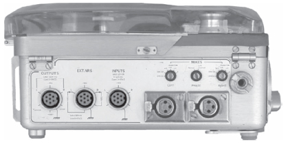
Figure 22.13 Left flank Input panel.
The speed and power indicator (item 15 in Figure 22.3) works just like the Pilot indicator. When you roll, this flag indicator will flip on and hold steady. It tells you that your speed is constant and that your power is good. If the flag flickers or goes out, you know that you are not going to have proper lip sync. Naughty, naughty—you have not kept good account of your battery power and they have dipped below the safe level that we have talked about in this chapter. Check your batteries by flipping the Meter selector to BATT and, if your batteries are croaking, of course, replace them. But, if your batteries are fine and the flags continue to flicker, cease using the machine. Get your backup unit out and immediately send your Nagra to your maintenance tech to be checked out.
The Modulometer
See the preceding paragraphs for discussion on this function.
The Tuchel In and Out Connectors
Line Inputs (Tuchel 7-Pin Connector)
Figure 22.13 shows the left flank side of the Nagra, or the Input side. Notice that the outboard Line inputs and outputs use Tuchel (pronounced too-shell) connectors and are located on the left side of the panel (Figure 22.14). The Microphone inputs, using XLR female input connectors along with their counterpart phantom power settings, are on the right side of the panel.
If you are transferring from another machine or using an outboard mixer to control your microphones and slating chores, you will patch into the Nagra using a Tuchel 7-pin connector. If you need to make or have a Tuchel connector cable made, a schematic of the pin assignment configuration is shown in Figure 22.15.
Remember, when you use the Tuchel connection for an outboard mixer or input from another machine you must go to the front panel of the Nagra and flip the Mike/ Line switch (item 8 in Figure 22.3) down to Line.
EXT.NRS (Tuchel 7-Pin Connector)
If you are utilizing an outboard noise reduction system, you will connect the system via the Tuchel 7-pin connector into this screw socket. You must then go to the front panel of the Nagra and flip the switch (item 9 in Figure 22.3) up to NRS. This will send the signal out to the outboard noise reduction gear and return it back into the Nagra after the noise reduction encode is effected.
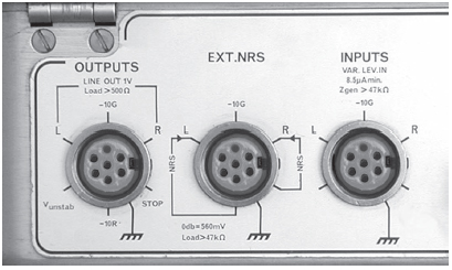
Figure 22.14 Closer view of the Tuchel inputs.
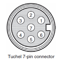
Figure 22.15 Tuchel schematic.
Line Outputs (Tuchel 7-Pin Connector)
If you are using the Nagra as a transfer machine you may output the signal either through the Tuchel 7-pin connector on the far left of the left-side panel or from the banana plug options (see the following list) on the right-side panel.
Should you need to custom fabricate your own connector cables, Nagra wiring assignment specifications are listed next. The illustration of the Tuchel connector in Figure 22.15 shows the external view of chassis connector or plug from the soldering side.
Outputs
1. Channel 2 (right) output: output voltage is 1 V at 0 dB, minimum impedance load 500 Ω (Ohms).
2. -10 G: -10 V stabilized voltage output, maximum current 100 mA for all -10 V terminals.
3. Channel 1 output (left) identical to channel 2.
4. Vunstab: unstabilized power supply voltage.
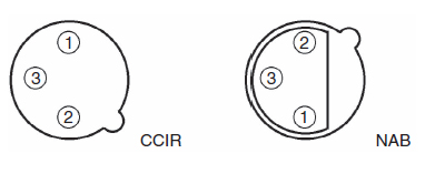
Figure 22.16 XLR connector schematic.
5. -10 R: -10 V stabilized voltage output available on record only, maximum current 100 mA for all -10 V terminals.
6. Stop: input for the motor stop control (connect to -10 V to stop).
7. Ground.
EXT.NRS (Noise Reduction System)
1. External noise reduction system output channel 2 (right).
2. -10 G: -10 V stabilized voltage output, maximum current 100 mA for all -10 V terminals.
3. External system output, channel 1 (left).
4. External system input, channel 1 (left) minimum input impedance 47 Ω.
5. External system input, channel 2 (right) minimum input impedance 47 Ω.
6. Ground (common).
Inputs
1. Channel 2 (right) input, impedance variable from 0 to 5 kΩ when switch 11 is on ST. HS, current drive with minimum source impedance 47 kΩ current to obtain 0 dB at maximum sensitivity 7.8 μA.
2. -10 G: -10 V stabilized voltage output, maximum current 100 mA for all -10 V terminals.
3. Channel 1 (left) input, identical to channel 2.
4. Ground for input signals.
The Microphone XLR Connector
The first thing you will want to take note of is the difference between the NAB wiring scheme and the CCIR scheme (Figure 22.16). Again, Nagra wiring assignment specifications are listed should you need to custom fabricate your own connector cables. The illustration of the XLR connectors shows the two standard wiring schemes as external views of the chassis connector or plug from the soldering side.
The Microphone XLR Inputs
The two microphone XLR inputs, unlike previous monaural models, record on two dedicated channels. I know that seems very obvious, but you have to remember that the previous Nagras were, in fact, monaural machines; even though they had two microphone inputs, they combined both signals into a single channel. Per industry standard configuration: Left is channel 1 and right is channel 2.
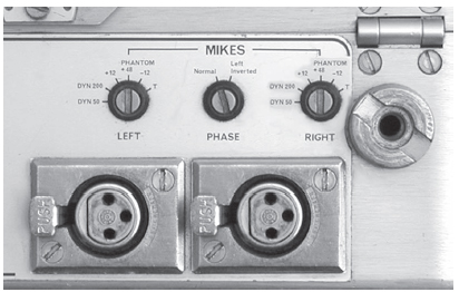
Figure 22.17 Close-up view of microphone XLR inputs and Phantom power selectors.
The Phantom Power Selectors
Nagra includes a six-option Phantom power supply for each input.
DYN 50: If you are using a dynamic microphone with an impedance of 50 Ω, 0.1 mV/μbar sensitivity.
DYN 200: If you are using a dynamic microphone with an impedance of 200 Ω, 0.2 mV/Ωbar sensitivity.
+12: If you are using a condenser microphone with a 0.1 mV/Ωbar sensitivity and require +12 V phantom powering.
+48: If you are using a condenser microphone with a 0.1 mV/Ωbar sensitivity and require +48 V phantom powering.
-12: If you are using a condenser microphone with a 0.1 mV/Ωbar sensitivity and require -12 V phantom powering.
T: If you are using a condenser microphone with a 3 mV/Ωbar sensitivity and require +12 V T-powering (Tonaderspeisung).
The Phase Selector
Occasionally you may have microphones that do not have matching wiring schematics and you may need to invert the phase of one mike to properly record against another one. If you flip the screw slot switch (located between the two Phantom power selectors) to the right you will invert the phase of channel 1 (left).
The Output Side
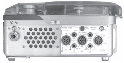
Figure 22.18 Right flank output panel.

Figure 22.19 Close-up of output panel.
Figure 22.18 shows the right flank side of the Nagra, or the Output side. Notice that the grill on the left part is where the built-in loudspeaker is. This speaker only works when the Main Function selector bar is turned all the way down to the second Playback position with the double-cone icon. On the Nagra IV-S the speaker volume is controlled by the Volume Potentiometers. On older Nagra models, there is a volume control screw, sometimes located on the left flank side of the Nagra just below the Phantom power selector; other models have it just to the left of the loudspeaker up near the shoulder strap bolt.
External Power Pack—6-Pin Tuchel
The Nagra can work off of a 50 or 60 Hz AC power adapter that comes with the Nagra package. The power pack uses a 6-pin Tuchel connector to attach rigidly into the screw socket to feed the machine (Figure 22.19). You must go to the front panel of the Nagra and flip the Power switch (item 1 in Figure 22.3) up to External.
You will find that most mixers are very reluctant to try to use the power pack out in the field, feeding from an unknown and/or suspicious power source. It works fine for interior and stage work where known power feeds are dependable.
Line Outputs (via Banana Jacks)

Figure 22.20 Cue Tuchel 7-pin connector.
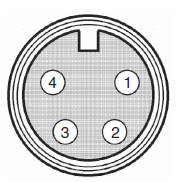
Figure 22.21 Pilot Tuchel 4-pin connector.
Output transfers can be efficiently made using banana jacks, feeding from the left and right banana ports just below and to either side of the 5-pin Lemo Time Code connector. The ground banana jack ports are on either side of the Cue 7-pin Tuchel connector.
Cue Tuchel 7-pin connector: This connector is for recording and playback on the pilot track. The illustration of the Tuchel connector in Figure 22.20 shows the external view of the chassis connector, or plug, from the soldering side.
1. Modulation signal input.
2. -10 V stabilized voltage output, maximum current 100 mA for all -10 V terminals.
3. Pilot signal input.
4. -10 V stabilized voltage available on Record only, maximum current 100 mA for all -10 V terminals.
5. Voltage terminal to activate the FM modulator.
6. Signal output (direct or recorded).
7. Ground.
Pilot Tuchel 4-pin connector: This connector receives signal input for the pilot track. The illustration of the Tuchel connector in Figure 22.21 shows the external view of the chassis connector or plug from the soldering side.
1. Ground.
2. Clapper: reference oscillator or crystal pilot generator control input.
3. Xtal: 50 or 60 Hz internal crystal pilot generator Output.
4. Pilot In: pilot signal Input.
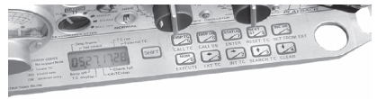
Figure 22.22 Time Code panel.
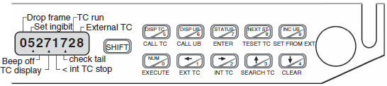
Figure 22.23 Pull-out Time Code panel.
Time Code In/Out
This 5-pin Lemo connector can either import an external Time Code signal or output the Time Code signal generated from the internal generator.
The Time Code Option
Some Nagra models, including the one featured in this chapter, are equipped with a pancake thin Time Code panel, which slides forward from the underside (Figure 22.23), tucked neatly between the two front stumpy feet on a scissor fold-out mechanism.
The Nagra can accept an external time code signal (via the Time Code connector on the right flank panel) or it will default to using its own generated time code signal. When using a Smart Slate, plug the Time Code wireless transmitter into the Time Code In/Out connector on the right-side output panel. The Smart Slate will display whatever time code the Nagra is generating for visual reference by the camera when the clapper assistant holds out the slate to snap sync. The illuminated red numbers make it easy for the assistant picture editor to sync the dailies later in picture editorial.
If you want to check the time code status, press the Status/7 button. Unless you want to record in a Drop frame mode, there should not be the little marker under where “Drop frame” is shown on the far left-hand side of the display. If there is a marker, it indicates that you are recording “Drop Frame Time Code,” which is not what you want if you are recording for film projects. Press Next Status/8 button to check the frame rate. It should read “30 Fr.” Thirty frames per second NDF (nondrop frame) is the industry standard for film cameras running 24 or 30 fps.
To clear the Time Code panel of previous programming, press the following buttons in this order: Shift, Status/7, Num/0, ≥/2, Num/0, Num/0, Shift, Num/0 (or, if you wish to read the words under the buttons: Shift, Enter, Execute, INT TC, Execute, Execute, Shift, Execute).
To program the user bits for use in the date format, press: Num/0, ≤/1, Num/0, DISP UB/6, Shift, Execute.
To enter the time of day, press the buttons: DISP TC/5, NUM/0, then the Hour, Hour, Minute, Minute, then Num/0, Num/0, Num/0, Num/0, Shift, Enter.
To enter the date, press the buttons: DISP UB/6, Num/0—then the Day, Day, Month, Month, Year, Year—then Num/0, Num/0, Shift, Enter.
To display this new Time Code, press the button: DISP TC/5.
To program the Nagra for Record Run time code (or code that advances only while the machine is in Record mode), press: Shift, Enter, Num/0, ≤/1, Num/0, Num/0, Shift, Execute.
Note that the last feature is only on machines with software version 1.95 or above. To check what software version is on your Nagra, press the button Status/7, and then repeat pressing the button Next Status/8. To return the machine to a regular time code mode, follow the instructions for clearing the time code panel and setting the time of day again.
AUDIO TECH MAINTENANCE
The following is a list of authorized Nagra IV-S sound service centers that render outstanding services in the United States.
Nagra USA, Inc.
Nancy Belt, General Manager, 357 Riverside Drive, Suite 230C, Nashville, TN, (615) 726-5191
California
Alternative Audio Services, 5750 Camelia Avenue, North Hollywood, CA 91601, (818) 764-5164
Dan Dugan Sound Design, 290 Napoleon Street, San Francisco, CA 94124, (415) 821-9776
Location Sound Services, 10639 Riverside Drive, North Hollywood, CA 91602, (818) 980-9891
The Sound Check, 5435 Cahuenga Boulevard, North Hollywood, CA 91601, (818) 766-2920
Maryland
Vark Audio, 8101 MacArthur Boulevard, Cabin John, MD 20818, (301) 229-0288
New York
Audio Services, 353 West 48th Street, New York, NY 10036, (212) 977-5151
Professional Sound Services, 311 West 43rd Street, New York, NY 10036, (212) 586-1033
Tennessee
Trew Audio, 240 Great Circle Road, Nashville, TN 37228, (615) 256-3542