
Chapter 6
From the Set to the Laboratory
“That's a wrap for today!” shouts the assistant director. The camera crew breaks down the camera gear and carefully packs the cases into the camera truck. The second assistant camera person (known as the clapper loader in England) is responsible for the exposed negative. He or she sees to it that each roll of negative is carefully placed back in its opaque black plastic bag and secured inside the aluminum film can. The can is then taped so that it will not spill open accidentally. With a black Sharpie or a permanent felt marker, the second assistant labels each can, making sure the identification roll number matches what is on the camera report. The laboratory copy of the camera report is taped to the top of each can. When all the cans have been securely packed, taped, then labeled, and when they have their corresponding sound reports taped on properly, each film can is then packed in a moisture-proof bag. The second assistant camera person places all the film cans in a thermal box for delivery to the laboratory and gives the script supervisor a copy of each camera report to include with the paperwork. Another copy of each camera report is sent to picture editorial, and a third copy is sent to the production office.
The sound crew breaks down the mixer's sound cart, carefully packing the gear into the sound truck. The production mixer packs up the clone hard drive, back-up DATs or Vi” rolls to be shipped back to sound transfer or directly to picture editorial. The original copy of each sound report is folded up and placed into its corresponding box of Vi” tape, or wrapped around each DAT. As in the camera department, the sound mixer gives the script supervisor a copy of each sound report to include with the daily paperwork. A copy of each sound report is also sent to picture editorial and to the production office.
TRANSFER PROTOCOL
Before the film and sound rolls leave the set, the script supervisor reviews and confirms all circled takes with the picture and sound departments. If the location is within driving distance of the film laboratory and sound transfer, then a PA (production assistant) drives the rolls of film negative and sound rolls to their respective processing facilities each night.
Delivery Format
The negative has been developed, but what does the laboratory deliver to the client? Will the project be cut on film or cut digitally? These types of questions determine the protocol the production company follows to successfully carry the show through the various phases of postproduction to completion. Before the cameras even begin to roll, the director, producer(s), director of photography, and picture editor discuss the various ways to handle the picture editing process (described in more detail in Chapter 7). Once the picture editing process is determined, the technical parameters and spec sheet for delivery virtually dictate themselves.
Shot on Film—Cut on Film
If it is decided to cut on film, then the laboratory must print 1-light daily workprints of all the circled takes advertised on the camera report. Sound transfer must transfer a monaural 35-mm mag stripe of all circled takes on the sound report. On rare occasions, a project requires multichannel dailies, such as music events. In such a case, the production company may require that 2-, 4-, or even 6-channel 35-mm fullcoat transfers be made.
Early each morning, the picture editorial runner picks up the 1-light workprints at laboratory, then gets the rolls of single-stripe audio track from sound transfer. Once the picture assistant and apprentice sync all the dailies (discussed further in Chapter 7), they run the reels late in the afternoon or early evening when the director, producer, and picture editor convene to review the material. The first picture assistant must scrutinize the audio sync carefully during the projection of the dailies, as anything that may play back out of sync must be corrected before the reels of picture and their corresponding reels of mag stripe are edge-coded.
Once the dailies are screened, the first picture assistant and apprentice return the reels to their cutting rooms to make any last-minute adjustments to fix sync issues that may have been noticed during the screening. Once these adjustments are complete, the reels of picture and track either are sent out to an edge-code service or the picture editorial crew may have rented their own edge-code machine, such as the Acmade, so that they may do the work themselves. It is absolutely imperative that this edge-code process be done precisely with a focused attention to perforation accuracy as well as keeping the code number assignments straight. The edge-code number is printed onto both the picture and the mag stripe film. Note that the numbers must line up exactly parallel to each other.
Once editorial is satisfied that the daily rolls are in perfect sync and edge-coded, then they are sent to a telecine service where videotape transfers are made. A copy is sent back to the set for review when and if needed for a variety of reasons.
The picture and sound rolls are then returned to picture editorial where they are either broken down in a traditional “per scene/take” technique and carefully rolled up in individual rolls, or more commonly turned into what is known as KEM rolls. Each set of reels can be spun down at high speed on a flatbed editing machine to review alternate takes and extract the footage the editor wants to use in the final cut.

Figure 6.1 Editing flow protocol for Shot on Film—Cut on Film.
The picture editor is now ready to commence the editing process—cutting picture and soundtrack on separate rolls, in perfect sync with each other. This is the traditional “shot on film, cut on film” technique. When the picture is locked, the workprint is turned over to make duplicate copies (usually in a video format with time code) for sound editorial, then sent to the negative cutter to conform the negative to match the workprint.
This technique is virtually extinct in the form that has just been described, but it is important that one understands how things were done, especially if you find yourself working in film restoration or resurrecting vault footage from older films to construct new version cuts, new behind-the-scenes material for “bonus materials” on DVDs, and so on. It also helps one to understand why things are done the way they are—the roots of our art form.
To follow the four basic cutting protocols step-by-step, which may make it easier on the eyes than to look at one mass chart that seems a little overwhelming (wait until you see Cut-and-Conform) you can use the interactive DVD supplied with this book. On the main menu, choose button #1 SOUND—and OVERVIEW. A submenu will come up. Choose submenu button #6 PICTURE EDITORIAL PROTOCOLS and the next submenu will present you with the four protocols discussed in this chapter (reviewed for you step-by-step by a calm soothing narrator). Choose which “protocol” you wish to review and press the button. The exact chart, shown in this book, will unfold for you, panel-by-panel, in a process that should make it much easier to assimilate.
Edge Code and Key Codes on Film
While we are on the subject of working with film, now would be a good time to review what edge code numbers are and the difference between them and key code numbers.

Figure 6.2 Edge codes and key codes, the two essential numbers on film for unique identification and sync.
On the 1-light workprint you see two sets of numbers. The first set is the edge code numbers. These numbers are latent images that have been photographically printed into the original negative by the manufacturer at the time of its creation. The colloquial term is “picture keys,” or often just “keys.” These numbers are printed identically into the 1-light workprint, if the laboratory's optical printer exposes the edges of the film at the same time as the picture image.
These numbers serve two functions. First, a piece of film can be picked out of the bottom of the trim bin or off the cutting-room floor, and, by reading the edge code number, you can look up the designation number in the code book (see Chapter 7). From there, you determine from exactly what scene, angle, and take number it is, as well as from what camera roll of negative it was printed.
Second, the negative cutter uses these numbers to not only find what negative roll to access but to visually match the exact frame to make the cut. I can vouch for the ease and necessity of this system, as I have had to match far too much footage by visual image alone. Many years ago, a project I worked on did not have the edge code numbers printed through on the workprint.
The edge code numbers are printed onto both the picture workprint and the mag stripe film in exact sync to each other. If they are not in exact parallel sync, then having the edge code number is obviously useless.
More than one numbering technique can be utilized when it comes to edge code. Some like to lock the start mark at the head of the roll and then reset the prefix code and footage counter, thus yielding the traditional letter and footage as follows: A A 1000. Some picture assistants like to set the number codes according to the day of the shoot; in this case, the first day of the shoot is AA, the second day is AB, the third AC, and so forth. Because a single day's shoot very rarely yields over 9,000 feet of dailies, it follows that no need would exist to move on to prefix AB until the second day's dailies.
Many first picture assistants who use the Acmade edge-coding machine to print their own edge code numbers onto the workprint like to print the edge code numbers in a sequence that lists the scene, angle, and take as the number prefix, followed by the footage count, such as 37A1000. This means that this is scene 37, set-up A, take 1. Custom coding each “angle” and “take” in this manner obviously takes much more time than simply setting the start mark at the beginning of the roll and letting the entire roll of film run from top to bottom. However, the organization and speed gained later by the incredible ease of being able to pick up a trim of picture and/or production audio track and instantaneously being able to know the scene/take are of inestimable value.
Shot on Film—Cut Nonlinear and Conform
If the film is to be cut electronically, digital systems such as Final Cut Pro and Avid are popular choices by professionals. A series of refined decisions must be made to structure a procedural protocol to deliver the picture and production sound into the digital nonlinear environment. These decisions must be made in preproduction, as they affect the entire postproduction process to come.
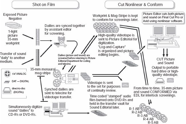
Figure 6.3 Editing flow protocol for shot on film—cut nonlinear and conform.
Many times, especially on larger budget pictures, the production company wants more latitude in screening work-in-progress, but prefer that it be done on film and not video projected. In this scenario the negative is developed and a 1-light workprint is struck, as before. The sound daily takes are transferred both digitally to an audio file for nonlinear editing as well as a 35-mm mag stripe transfer made.
Workprint and mag stripe sound are synched together in the traditional fashion and screened for sync and edge coded as in the usual fashion. The difference is that in this case the workprint and mag stripe rolls are racked for future use and not cut in the traditional picture-editing process.
When the picture and track are sent to a telecine service a high-quality (DigiBeta) videotape is transferred and picked up by picture editorial. The videotape can either be contracted to an outside company to do a “log-and-capture” into QuickTime files in the specified format, or the assistant picture editor can do the work at picture editorial.
The digital audio files (usually AIFF, .WAV, or SDII) that were simultaneously transferred when the 35-mm mag-stripe daily was made, are burned onto a CD-R or usually a DVD-R. This is not only a medium to conveniently deliver the files to the client, but becomes a valuable vault back-up should picture editorial suffer a drive meltdown or media file corruption.
From time to time picture editorial will be called on to conform the workprint and 35-mm mag stripe to a particular cut version. The EDL (Edit Decision List) of the nonlinear edit session will be printed out and the assistant editors will access the workprint and mag stripe and match the cuts, or what is commonly called “conforming.”
This technique is becoming less and less popular as higher quality video projection venues become more available so that the production company may properly present their work-in-progress cuts and/or conduct test audience screenings. But as I have still found a few projects and filmmakers that embrace it to this day, it is included in this book for you to understand this particular option. With today's evolving laboratory techniques and digital intermediates, there is no longer any reason to actually “cut” the negative, in the traditional fashion.
When the locked picture is turned over to sound editorial, the supervising sound editor will probably want the original digitized audio files that were burned to CDR/DVD-R and held for post-dialog editing, rather than use a generation-transferred video transfer audio from the telecine.
Later, when you make a QuickTime picture output for sound editorial, you should make a “video” and “audio” combo (self-contained file of course)—but you also want to ouput an audio OMF file to go with it.
Big Note: The use of OMF (open media framework) software to greatly accelerate and streamline the dialog editing process over the original discipline of phasing reprints against the work track, your picture editorial protocol must have imported and used the “professionally clean audio transfers” during the editorial process—as the soundtrack that is captured from a videotape transfer from the laboratory, even a DigiBeta, is going to have an inferior quality of audio than a digital-to-digital audio transfer, whether by FireWire download from the digital audio recorders drive or by high-quality A-to-D converter processors that professional audio transfer facilities use should the sound mixer opt to record in analog.
The sound editorial team will take this OMF file and decode it, which will extrapolate and create a Pro Tools session with all of the material that picture editorial cut, exactly in sync with where the picture editor cut it and in the layers of tracks that the picture editor created.
Note: When picture editorial outputs the audio OMF file, a menu will appear, asking what kind of “handles” you wish to build into the output. This is the sound material prior to when it was cut and after it was cut, which can be extended by the sound editor who may need to look for valuable fill presence or other audio needs.
In the early days of nonlinear editing (back when we thought a 9-gig drive was huge), it was a drive space issue as to how many pre- and post-handles we could afford to dedicate to an OMF output. With today's terabyte set-ups, storage space is far less a problem. I cannot think of any serious dialog editor who does not want as many of those audio file pre- and post-handles as he or she can have. It is therefore vital that picture editorial not ignore this menu option, but ask sound editorial how long the handles of the audio file should be factored into the output. Unless drive storage is an issue, picture editorial will always be told, “As long as we can have them!”
It is also at this critical output point that you have an experienced craftsperson set up the output settings; otherwise the OMF extrapolation of a Pro Tools session will not be in sync!
As with the “Cut on Film” protocol, you can access the “Shot on Film—Cut Nonlinear and Conform” protocol on the interactive DVD with this book as explained earlier. This particular protocol especially lends itself to being better understood by reviewing the panel-by-panel narrative.
Shot on Film—Cut Nonlinear
The decision may be made that the laboratory will develop the negative and make a reverse (positive image from the negative) video transfer to a high-resolution videotape such as the DigiBeta or even make full-resolution QuickTime video files (depending on the services the particular lab is capable of and offers). Circled takes are not necessary for the laboratory process with this style of delivery. All the footage is transferred to tape, thus giving picture editorial access to all the footage, rather than just the circled takes. This tape would come to picture editorial without sound, leaving the process of syncing the production audio track to the assistant picture editor and the apprentice.
Many laboratories offer services for handling the daily sound rolls as well, including syncing the slates. The producer decides either how much to pay out of pocket to an assembly-line style of delivery, or if the film's own crew will personally do the work, adding the care and passion that a project's own picture editorial team is bound to bring to the effort.
But here is the pivotal issue—precise log-and-capture digitizing chores should not be assigned to “get-start” interns and/or learning apprentices without the strict supervision of an experienced first picture assistant who is a seasoned veteran of how to properly import and prep picture and audio files for the picture editing process.
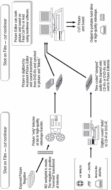
Figure 6.4 Editing flow protocol for shot on film—cut nonlinear.
I said it again and I will harp on it again—junk-in, junk-out! Mistakes made at this critical point in the process are going to have astounding collateral cost ramifications down the line. All too often the producer will hire what appears to be a cost-effective way to get the picture from the lab and into the computer, so he or she will entrust such duties to an intern working for free or an apprentice just getting started. The ironic and sad part about this all too common mistake is that the producer does not realize that when these issues come up weeks or months later he or she is paying out far more money to fix problems that were created in a false decision of economy.
The world of file formats, innovations in laboratory delivery, and specific project demands dictate that you (or the editing team you employ) communicate closely with the laboratory service that you use. Before camera equipment and pictorial formats and audio recording decisions are made, you have to have your team members walk through the process from stem-to-stern so that everybody is on the same page. This will help eliminate, or at least reduce, the unseen surprises that always seem to rise up when this necessary collaboration is not practiced with a discipline.
That said, your picture editor will commence the assembly and editing process as your production shoot progresses. After production wraps and pick-up shots have been decided and completed along with all of the other visual special-effect inclusions, you will output your picture and sound at full resolution to either a hard drive (in digital file form) or videotape.
Please note that it is not a wise idea, if you are working on a serious project, to have picture editorial handle the strict discipline outputs of picture lock for postproduction sound editorial, especially with the increasing use of “digital intermediates.”
In recent conversations with some of my colleagues who have already encountered working on films that are using digital intermediates, they have experienced serious sync issues—to the point that several post-sound firms require that they will not accept a picture output to prepare the sound elements for unless the output is handled by a reputable professional telecine service. Please take this last sentence of advice to heart. It is clearly obvious that digital intermediates are the way of the future in filmmaking, but in order to address new innovations in the filmmaking process, you must listen to those who have been on the frontlines of actually working with and having encountered the collateral issues that every new innovation invariably brings with it.
You can waste days, if not weeks, of precious schedule time and wrestle with the frustration and finger-pointing of why track drifts out of sync or who is to blame. The more technologically encumbered our craft becomes, the more the vital it is to rely on veteran craftspeople. A smart producer will quickly realize that a well-paid picture editor and assistant picture editor with the resumes of know-how and experience to accomplish the job are much more cost-effective than placing freebie interns and get-start apprentices in an effort to cut costs. Okay, soapbox lecture over.
Be careful how you output your final locked picture (as well as any temp-dub versions along the way) and you should find this protocol very satisfying.
As with the previous protocols, you can access the “Shot on Film—Cut Nonlinear” protocol on the interactive DVD with this book for review.
Shot on Video—Cut Nonlinear
Without question, the most activity in shooting productions, whether they be documentaries, student films, television (both short and long form), and more and more feature work, is various levels of high-quality video.

Figure 6.5 Editing flow protocol for shot on video—cut nonlinear.
All video cameras have a built-in microphone, but any production coverage outside of personal home videos and/or news work insists on a traditional sound mixer and microphone boom operator to capture the expected audio quality that serious filmmakers cannot do without.
High-definition video brings a whole different set of media demands and disciplines than traditional video shoots. Fortunately, the learning curve on high-def is quickly taking hold and we are seeing fewer and fewer directors and producers poised with a razor blade on their wrists. But as I stated a few paragraphs before, once you decide if you are going to be filming in a more traditional video format or if you are going to shoot high-def, your cinematography, sound, and picture editorial department heads have to walk the path on paper before you start shoveling money out the door. Preproduction preparation is the cheapest and most cost-effective process in any production.
You will want to record a “guide track” on the built-in microphones on the video camera, and the assistant editor will want to capture this in the digitization process as a guide track to reference. Your sound mixer and boom operator will be capturing the “good stuff” with their own equipment, using the best audio recorders and microphones that the budget will allow. Whether you have a professional sound transfer service digitally import this audio or you have your picture editorial team handle these chores is your decision.
The “camera” soundtrack, upon “log-and-capture,” will be linked to the picture, of course, and therefore becomes a very handy sync-checker-upper when the assistant imports the sound recording teams “good stuff” and syncs the dailies using the better audio files.
As with the previous protocol, when you make the QuickTime picture output for sound editorial, you should make a video and audio combo (self-contained as we discussed).
In the majority of instances, these projects are outputting the very material that they captured. In other words, you will not have to worry about the disciplines of video rate and film rate interpretations to resolve sync. It is, therefore, much more likely that picture editorial will generate the QuickTime and OMF files from the picture editorial workstation itself, rather than contract that work out to a telecine. This does not mean that you can make certain assumptions and not be careful to closely check the correct output settings to guarantee each video frame equals a video frame and that you are not altering the real time in any manner.
Even though more and more editorial software and user platforms are using computers with fast enough processors, high definition can still be sluggish at full resolution. I am sure by the time I write the fourth edition of this book, this comment will be obsolete, but for now, it is safer to check with sound editorial first and ask how they want the picture output (resolution wise).
As with the previous protocols, you can access the “Shot on Video—Cut Nonlinear” protocol on the interactive DVD for review.
Digital Food for Thought
Careful thought should be given to the choice of which nonlinear editing system to use. All systems are not created equal. All too often, I have seen a production company make a decision based on the appearance that a particular system was much cheaper to use and therefore should be more cost-effective, only to find out that the collateral ramifications of going cheap on the nonlinear system inflicted numerous extra costs on the postproduction budget when the sound-editorial process commenced.
Another mistake is believing the laboratories and sound facilities when they tell you they are equipped and qualified to do specific services you may require. I knew one laboratory that told the producer that the film was being developed right there on site, but in actuality it was being flown counter-to-counter to Los Angeles for processing by another laboratory subcontracting the work. The first laboratory did not want to take time away from the services and handling they did do. The problem then, and still, is that the more you subcontract and fragment the services, eliminating those craftspeople who could truly be handling the QC (quality control) of your lab work, the more mistakes, lost footage, misunderstandings in specifications, and general lack of personal involvement and commitment to excellence you will find.
Before you settle on a laboratory or sound facility, do yourself and your production budget a big favor and check out various possibilities. Talk to other producers and especially to postproduction supervisors who deal with numerous laboratories and sound facilities. Talk to those craftspeople who have had actual working experience with the laboratories or sound facilities you are considering. First-hand trench-warfare experience by those who work with these facilities is invaluable in guiding you through your production minefield.
DATA IS GOLDEN
Regardless of whether you decide to edit on film or digitally, regardless of what editing platform or protocol is chosen, the underlying constant to all procedures is that at this stage in the negative development through syncing of dailies, the precise and correct entry of data is crucial. Whether the key and edge code numbers are manually entered into the code book or into the information buffer of audio and picture files in the digital domain via the computer keyboard, this information is incredibly difficult to correct once entered incorrectly. Untold time and energy will be wasted trying to find a negative or sound roll because the code book data has either not been entered or the entries are sloppy and/or incorrect.
Unfortunately, this critical moment in the organizational structure of a project suffers the worst from fatigue and dyslexia. Many of us in postproduction have discovered that more craftspeople suffer from some form of dyslexia than one might think. Be careful to recognize such tendencies in yourself and either delegate certain critical responsibilities for data entry to someone else or be extremely cautious and thorough, double-checking numbers before you proceed. Incorrect data entry completely invalidates the ability to successfully utilize OMF functions later. In today's highly pressured schedules, losing the ability to use either the OMF or post-conform function severely slows down dialog editorial, potentially costing thousands of extra dollars to have dialog takes retransferred from source, not to mention having to endure the slow and painstaking process of phase matching (discussed in Chapter 14).
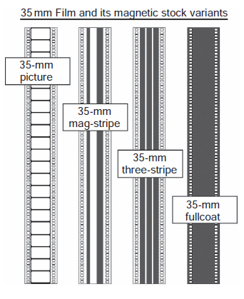
Figure 6.6 The 35-mm magnetic stocks. There are the four kinds of 35-mm media used today, explained in detail in the text.
35-MM FILM STOCK VARIANTS
35-mm Picture
The 35-mm film stock on the far left of Figure 6.6 is photographic stock. Numerous types of photographic stocks exist, most of which are used to capture the visual action of a motion picture. Another reason for using photographic stock may be, for instance, to transfer the 2-track matrix stereo sound mix into the optical image that is combined photographically with the visual picture on the final release prints. The example shown has the classic four perforations per frame. Regardless of the incredible advancements in 24 P and high-definition digital projection, 35-mm film stock is still the most popular, and, to date, it renders the most cost-effective image resolution, which will carry the industry well into the next century. 35-mm film is also a global standard. Whether you take your film to Europe, Australia, China, the far reaches of Africa, or upper Siberia, the technical specifications of 35-mm are worldwide.
35-mm Mag Stripe
This 35-mm stock is used for monaural audio sound applications. The wide magnetic stripe on the right side of the film is for the sound. The thinner stripe on the left is called a “balance” stripe (also known as “guide” stripe) so that the film does not undulate as it tracks along in the Moviola, on the KEM, or especially on the re-recording stage playback machines. The balance stripe allows the film to roll up onto itself with an even thickness due to the emulsion layer.
35-mm Magnetic Three-Stripe
This 35-mm stock is also used for audio sound applications. A nearly obsolete variant of stripe formats, three-stripe has been recently revived at several major studio sound departments. Additionally, it is far easier to work with, as it uses an acetate base that tears, unlike fullcoat, which uses a polyester base that does not break. It is also far more economical than fullcoat for the preparation of stereo and/or multichannel sound work.
35-mm Magnetic Fullcoat
This 35-mm stock is also used for audio sound applications. Fullcoat is the most popular and dynamically the best sounding audio format for motion picture and television production. Because of the high rate of speed (90 feet/minute) with which the film passes over the head-stack array, and because of the breadth of the sound heads, the user can load up and saturate the magnetic properties of the film much more heavily than with other analog media, such as 24-track audiotape.
Most “digital” motion picture releases today are first mixed to 35-mm fullcoat in a 6-track configuration to take advantage of the full and rich dynamic range. Because fullcoat has a solid magnetic surface, the user can utilize one of a variety of configurations.
LINE-UP TONES
The disciplined use of line-up tones is the only basis of creating and later duplicating a precise and matching level of audio reproduction. Without it, we can only take our best blind guess, which even at its best never reproduces an exact duplication of the original. For this reason, the vast majority of audio craftspeople and sound facilities throughout the world have adopted and conformed their specifications and recording levels to uniformity by using SRTs (standard reference tapes). Equipment manufacturers design and build their products to operate to these standards. Facilities use SRTs to adjust their playback machines to properly reproduce the standard. This guarantees that a tape recorded halfway around the world will reproduce virtually identically in the studio environment so that 1:1 prints (the first one is identical to the copy made from it) can be transferred from the tape source as exact copies to the original.
In theory, if everyone used the identical reference tape and adjusted their machines correctly, recording a sample of the tones on the head end of recordings would be unnecessary. However, because a variety of reference levels can be used and all machines do not record perfectly and all operators do not set up their machines correctly, the recorded tones at the head of a tape ensure that the recording is reproduced correctly.
Line-up tones are usually sine (for sinusoidal) wave or pure tones, not square waves. Line-up tones are laid down on the magnetic stock prior to the start mark. If the audio transfer is analog, as with 35-mm magnetic film or analog magnetic tapes such as 2-inch 24-track analog tape, the line-up tones are recorded at “0” level on the VU (volume unit) meter, unless specified differently on the tape's content label.
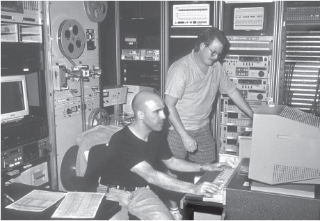
Figure 6.7 The transfer facilities at Technicolor-Weddington never rest. In the foreground, Bruce Balestier is transferring dialog loads from the original production source for a dialog editor. Behind him, Rusty Amodeo supervises the layback session so that it is correctly done the first time. (Photo by David Yewdall.)
A 1-kHz (referred to as a “thousand-cycle tone”) sine wave is the standard tone. If the transfer department is interested in very precise line-ups being made later, they follow the 1 kHz with a 10-kHz tone to adjust the high end, and a 125 Hz for adjusting the low end. Many who have been around awhile prefer to have a 40-Hz tone for the low end, but few sound facilities use it today.
If you are working with digital transfers, you do not have a VU meter, but a peak meter. In the digital world, “0” dB represents full scale or the absolute maximum recording level possible. Standard level then becomes some number of dB below full scale. Because digital and analog devices work together to accomplish recordings and re-recording jobs, an agreed-upon correspondence must exist between standard digital level and standard analog level. I have already discussed the standard analog level, but, in the absence of a precise digital standard, everyone has a different opinion on what the “0” VU is for them and their own recordings. The generally accepted standard digital level has been changing during the past few years.
VU and Digital Meters
When gray-market DAT machines were first available in the late 1980s, some sound facilities adopted -12 dB as “0” VU. Those of us who worked with, how should I say, high-concept, high-velocity sound effects projects discovered very quickly that -12 dB would not give us the sufficient headroom required for the thousands of vibrant and robust sound effects we were developing and delivering to the re-recording stages. Those who used -12 dB as “0” VU discovered clipping and a plethora of digital spiking.
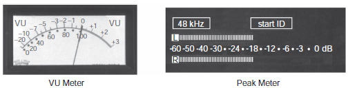
Figure 6.8 The two basic audio signal meters: the volume meter (VU) and the peak meter.
The hardest lesson to teach the creative user was that the digital world has only so many 1s and 0s.
Let us pause for a moment to clarify something that probably puzzles many creative audio users who do not hail from an engineering background. In digital audio, the number of bits assigned to each sample (not the sampling rate) limits the dynamic range. If you are working in a 16-bit system, you have 65,636 possible volume levels to work with in each sample of the recording. If you try to drive the signal to 65,637, you will experience clipping and distortion because no more 1s and 0s are left to use. Of course, the volume-level saturation geometrically increases as you work at a higher bit rate. If you were working in a 20-bit system, you would have 1,048,576 choices, and working in 24-bit would give you 16,777,216 for each sample!
It did not take long to find out that all the hard work of analog sound effect recording of the past couple of decades was being squashed and spiked, especially when the mixer had recorded the material very hot, saturating the tape. Recordists and sound facilities alike quickly discovered that the dynamic characteristics of many of their recordings were just too powerful to be properly translated into the digital realm.
In 1990, through a series of collaborations between manufacturers, sound mixers, and engineers, the theatrical and television industries settled on -18 dB as the digital peak meter equivalent to “0” VU, even though many of the DAT developers were designing their equipment for -16 dB. For several years, -18 dB seemed to be settling in fairly well.
Obviously, the best way to control overloading (clipping) the maximum level of your digital recordings is to bring the volume of the sound down by adopting a lower decibel level as a “0” VU equivalent. Today, almost all of the high-concept sound mixers and editorial firms have moved to -20 dB, and a couple have gone so far as to adopt an extreme -22 or -24 dB as “0” VU. Their audio engineers tell me they have come to the point that they need those extra decibels of headroom. I personally do not agree with that extreme choice.
Pink Noise
Pink noise is an electronic signal that has equal energy levels at all frequencies across the range from 20 Hz to 20 kHz. Pink noise is often used to make measurements of electronic systems and acoustic spaces. It has an advantage over simple tones in that all frequencies are present simultaneously, allowing the user to make frequency response measurements quickly. Using an audio spectrum analyzer, a “flat” system or acoustic space is represented as a flat, easily interpreted line on the display. Users of pink noise must be careful to utilize analyzers that offer signal averaging over time due to the rapidly changing characteristics of pink noise; they must also be certain that the measurement microphone has a flat response as well.
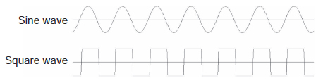
Figure 6.9 The same audio frequency played back first as a sign wave signal and then as a square wave signal.
Line-Up Tones for Your Own Use
Sound cues provided on the DVD that accompanies this book were carefully mastered so that you can use these line-up tones to check the performance and balance of your speakers.
The 1-kHz Sine Wave and Square Wave
The 1-kHz sine-wave line-up tone was mastered to read -18 dB on the digital peak meter (“0” VU). The 10-kHz sine-wave line-up tone was mastered to read -18 dB on the digital peak meter (“0” VU). 10-kHz tone is used to calibrate equipment to properly record and reproduce high-end frequencies.
The 40-Hz sine-wave line-up tone was mastered to read -18 dB on the digital peak meter (“0” VU). The 40-Hz tone is used to calibrate audio equipment to properly record and reproduce low-end frequencies, though many sound facilities use 100- or 120-Hz tone instead.
The pink noise was mastered to read -18 dB on the digital peak meter (“0” VU). You can place a spectrum analyzer in the ideal listening “apex” of the room and study your speaker reproduction characteristics. (Many consumer-level electronics stores offer excellent spectrum analyzer and audio pressure meters for amateur as well as professional use.) The 1-kHz square-wave line-up tone was mastered to read -18 dB on the digital peak meter (“0” VU).
TIME CODE: THE OBNOXIOUS ELECTRONIC CRICKET
What is time code? How is it used? Should we worry about more than one? Some of the most frightening postproduction war stories revolve around misunderstanding and misusing time code. I literally have seen craftspeople fall back against the wall and slump to a heap on the floor, holding their heads and crying with mental fatigue, because of mismatching time codes or because thousands of dollars of video and/or layback transfers were rendered useless after time code parameters were entered incorrectly. Time code is one of the most confusing and frustrating subjects to deal with in the postproduction process. It is important to get a good grasp on time code: what it does and how to use it as a valuable tool. Let us take a moment and appreciate its relationship to time and space.
In the beginning, before color television (and time code), there was black-and-white television, which operated at 30 fps (frames per second). Color television was introduced in 1953, and, to make color television compatible with the large number of black-and-white receivers, the engineers made a small adjustment to the television signal. They changed the frame rate from 30 fps to 29.97, which slowed it down by 1/10th of 1 percent.
No one noticed and no one cared—until time code came along. The first time code was used in videotape editing and counted 30 fps. If this time code was operated at exactly 30 fps, the time code generator and a normal clock agreed. After viewing an hour of program material, the time code and clock agreed that exactly 60 minutes and 0 seconds had passed.
However, because the television system operates slightly slower than 30 fps, the time code and the real-time clock do not agree. Imagine that you have two clocks, one with a slightly dead battery and one with a fresh battery. Because they are not both running at precisely the same rate, they do not stay in synchronization. Each counts hours, minutes, seconds, but their rates do not match.
When a television program assistant starts a stopwatch at the beginning of the program and then stops it at the end, time code and stopwatch will not agree. To make the slower-running time code address match the real time of day, the counting sequence was altered. It is important to remember that the time code rate was not changed; it still runs at 29.97, but the counting sequence was changed. The 0.1 percent speed change resulted in a difference of 108 frames per hour.
As we have discussed, American National Television System Committee (NTSC) systems run at 29.97 fps. Exceptions where video is run at 30 fps occur when special videotape machines are utilized during principal photography using motion picture cameras to film a television monitor screen. The television video feed is set to run at 30 fps to eliminate the black roll bar that would be visible on the television screen.
Keeping Film in Exact Sync
The most precise standard to maintain synchronization with film is the synchronizer, also known as a sync-block. When working with film, one can interlock the 16-mm or 35-mm picture and one or more 16-mm or 35-mm mag stripe rolls of sound together, side by side on sprocketed wheels (known as gangs) which are coupled to each other with a solid metal rod. When one wheel turns, the others turn exactly the same because they are physically coupled.
The synchronizer does two things. First, it keeps track of the position of the film by footage and frame number. Every frame has a unique identity. Second, it keeps the strands of film in exact synchronization. No matter how quickly or slowly the wheels are turned, the strands remain in perfect synchronization. This works because the film has sprocket holes (also known as perforation holes) that lace perfectly over the ever-revolving teeth of the synchronizer wheel. The film is kept from jumping off of the sprocket teeth because a locking arm has been lowered and clicked into place. Each locking arm has two rollers with groove glides that allow the sprocket wheel teeth to pass through, yet the roller holds the film in place against the wheel, so the film does not slip and slide out of sync with the picture or other mag stripe strands.
Figure 6.10 Editor with axe.
Each rotation of the wheel equals one foot of film. Numbers 0 to 15, in the case of 35-mm film, on the front of the wheel identify each frame around the circumference. An analog or digital numerical footage counter keeps track of how many times the synchronizer wheel has been rotated. If the wheel is turned 152 times, that means 152 feet of picture and tracks have passed through together in exact sync.
Invisible Sprocket Holes
Think of time code as an electronic multi-gang film synchronizer. Time code provides the same two functions for nonsprocketed media such as audio and videotape. In the case of videotape, every frame of picture has a unique identity, and, while sound can be subdivided into units smaller than one frame, we also refer to it in terms of frames. Time code uses hours, minutes, seconds, and frames instead of film's feet and frames.
We call the time code identity the time code address. Time code also enables synchronization among two or more elements (equipment) by providing a means to measure and control the speed, or rate, of the material. If a videotape and an audiotape each has matching time codes, then we can use a computer to keep the two in sync by making sure that the time code address and speed (rate) match. It is important to think of these two different functions: address and rate. As long as the addresses and rate match, it does not matter at which absolute speed the material is played. The rates, however, must match exactly for the two elements to remain in sync.
The “Pull-Down” Effect
Film cameras are operated in the United States at 24 fps. If the film is never converted to television, it would always run at 24 fps from the camera to the theatre projector. When film is converted to a television format for broadcast, a change is required.
If NTSC television ran at 30 fps, the conversion from 24-frame film to 30-frame television would be fairly straightforward. As the telecine transfer is made, it pauses the film every fourth frame and duplicates the fourth frame; then it rolls four more frames and duplicates the eighth frame; then it rolls four more frames and duplicates the twelfth frame; and so on. By doing this six times every second, the extra 6 frames needed for 24-fps film to fit a 30-fps format is achieved. You can see this for yourself by sticking a videocassette of a movie into your machine at home, then taking the remote control and pausing the action. Now push the single-frame advance button. The action advances a single frame. Push the button a few more times with a slow and rhythmic pace, so that you can study the single-frame movements. You will see that every fourth frame has been duplicated. Aren't your eyes quick enough to see those duplications in real time? No, neither is mine.
This does not fully solve the problem of film-rate conversion to television, however. NTSC television operates at 29.97 fps, or 0.1 percent slower (i.e., 1/10th of 1 percent), so when film is transferred to television it is necessary to slow, or pull down, the film rate the same 0.1 percent to 23.976 fps. When sound editors use a system that has a 29.97-fps video source, they must make sure that the production recordings, which are made with 30-fps time code, are slowed down the same amount as the picture was slowed down when it was converted to television. If you convert 0.1 percent to decimal format, it would be 0.001 (since 1 percent is actually 1/100th or 0.01, 1/10th of that would be 0.001). To prove the point, multiply 30 fps by 0.001 = 0.03; now subtract 0.03 from 30 fps (30 - 0.03 = 29.97 fps). Take 24 fps and multiply it by .001 (24 × 0.001 = 0.024) and then subtract 0.024 from 24 (24 - 0.024 = 23.976 fps). 0.001 percent would be 0.00001 in decimal format. Are we good and confused yet?
Addresses and Rates
There are four different time code address types and four different time code rates. The addressing serves only to uniquely identify each frame, while the rate is essential to maintaining synchronization. As you review the various time codes below, remember that computers count from 0 and not from 1, like most humans do.
Addressing Modes
• 24-frame: each frame is numbered from “0” to “23”
• 25-frame: each frame is numbered from “0” to “24”
• 30-frame nondrop: each frame is numbered from “0” to “29”
• 30-frame drop-frame: each frame is numbered from “0” to “29” (but there is a unique counting sequence)
Frame Rates
• 24 fps: American film systems run at this rate
• 25 fps: European film and television systems run at this rate
• 29.97 fps: American (NTSC) television systems run at this rate
• 30 fps: American standard for non-television-based materials run at this rate
There are six normally encountered time code formats. The valid combinations of addressing modes and rates are as follows:
• 24-frame addresses and 24-frame rate
• 25-frame addresses and 25-frame rate
• 30-frame nondrop frame addresses and 30-frame rate
• 30-frame nondrop frame addresses and 29.97-frame rate
• 30-frame drop-frame addresses and 30-frame rate
• 30-frame drop-frame addresses and 29.97-frame rate
These combinations cover 99 percent of the normally encountered addresses and rates.
Audio Time Code Signal
Time code is recorded onto video- and audiotapes as a special audible signal. It sounds very raucous, much like a constipated electronic insect with a bad temper, but time code-reader electronics can interpret this sound and convert it into computer-readable addresses. The computer listens to the time code and notes when transitions occur in the recorded signal. A transition occurs when the recorded signal changes from a positive-going waveform to a negative-going waveform, and vice versa.
The transition is important to the time code reader. The easiest transition to detect is a rapidly changing one. If the transition is very gradual, it is difficult for the computer to detect it. Square waves have rapid transitions. As the time code signal is copied from one tape to another, it is possible for the shape of this square wave to become distorted and the transitions more difficult to detect. When the time code signal is rolled off, it means that the transitions are not rapid, and the time code reader is having difficulty detecting them.
Time Code Specifications for Video Transfers
When ordering video transfers of either cut film or from nonlinear picture editing platforms, you want the videotape to be transferred with certain information windows as well as a precise designation of time code rate. Remember: be very specific about which time code format you want.
1. Transfer at 29.97 nondrop frame
2. Monaural production audio on Channel 1 (left)
3. Audio time code on Channel 2 (right) with visual time code address burned into the upper left of screen
4. Film footage and frame numbers burned into the upper right of screen
5. VITC (vertical interval time code, explained later in the chapter) on lines 17 and 19
6. Academy picture starts at exactly 000 feet and 00 frames, and time code corresponds to exactly 00 minutes, 00 seconds, and 00 frames
7. Time code “hour” designation matches the film reel number. For example, Reel 3 shows up as 03:00:00:00
8. 30 seconds of time code preroll before the Academy picture start
9. If VHS videocassette tapes are being created, time code and production audio are recorded on the normal analog channels
Drop-Frame Time Code
Drop-frame time code is so named because the counting sequence skips, or drops 2 frames, every minute except at the 10s of minutes. The time code address increases from 59 seconds, 29 frames (00:59:29)—stepping past, or dropping, the 1 minute, 0 seconds, and 0 frames (01:00:00) to 1 minute, 0 seconds, and 0 frames (01:01:00.02). The same number of frames per second is still there; each frame is still uniquely identified; they are just labeled differently.
Check for Drop/Nondrop
You have picked up a videotape that does not have a properly completed transfer label: it does not designate whether the video transfer was made drop or nondrop. In concert with the previous section about the operation of drop frame, simply insert the videotape into a playback machine and spin the image down to the nearest one-minute address. By putting the controller into a flip-frame job mode and carefully flipping from frame 00:59:29 to the next frame, you will know instantly if the tape has been transferred drop or nondrop. If there is no 01:00:00 frame, and the next frame is 01:00:02, then the tape has been transferred drop-frame.
VITC
VITC (pronounced “Vit-See”) stands for vertical interval time code. VITC is time code recorded in the television picture. It is not normally seen by viewers and is similar to the frame line that exists between frames of film. When projected, the film frame lines are not visible, and if one were to write numbers in the masked area between frames, these would not be seen during normal presentation. However, if the editor subsequently handles the film, the numbers are easily read. VITC operates in the same way. VITC is written into the television vertical interval. When the video machine is stopped, computers can read this time code very accurately.
Mixing Drop- and Nondrop-Frame Sessions
Most picture editors prefer to use nondrop-frame time code even though they are cutting on systems that are in fact running at 29.97 NTSC rate. The reasons vary, but perhaps it is related to the fact that some early editorial systems could not handle drop-frame time code and that the calculations involved in adding nondrop time codes were much easier than adding drop-frame time codes. Since the picture editors then were probably using nondrop, it made things easier when the sound and picture used the same addressing scheme.
With today's faster computers and much more sophisticated software utilities, however, it does not make much difference whether you use drop frame or nondrop frame, as long as you are consistent and all your people are using the same format. Even if they are not, the synchronization computers are capable of doing the math so that nondrop and drop-frame addresses can be easily synchronized.
Using Outboard A to D Encoders
If you are interested in having the best-quality digital sound transfers made from analog tapes or from 35-mm film, insist on having the material encoded or decoded through high-quality D-A/A-D (digital-to-analog/analog-to-digital) converters, such as the Apogee converters. Most people do not know that to make digital technologies such as the 8-track DA-88 recorders cost-effective and attractive, the manufacturers sacrificed high-end quality at the analog-to-digital and digital-to-analog conversion. Remember, there is no such thing as a free lunch. A really good deal is designed to appear as such because something, somewhere, was eliminated, sacrificed, or degraded to offset the expense.
Digital DA-88 recorders are fading away in favor of higher quality encoding platforms (such as the DigiDesign HD interface), not only because of the better sounding reproduction qualities, but also because of the limitation of only 8 channels per tape and the fact that digitizing 8 channels of a Foley session, for instance, required a transfer process.
Interlocking to time code meant “stem” type transfers, which would yield 8 audio files that would eat up a solid amount of disk space at the rate of 8 x 5 megabytes per minute (or 700-800 megabytes for a 20-minute reel). The net “performance” passages were usually 15 to 20 percent of that; or to look at it another way, you have 80 to 85 percent disk waste. This is why MR8 and MR16 technologies, which can quickly record a Pro Tools session straight to a removable hard drive, gained favor for a while. Straight to hard drive recording in ADR and Foley stage, re-recording predubing and final mixing is the standard, not the exception.
DA-88 technology served as a “bridging” intermedium, so to look to DAT technology as fading in popularity. With direct-to-disk recorders, such as the Deva, Aaton, Fostex, Sound Devices, and the Nagra V all utilizing high-quality straight-to-disk recording, the DAT is finding fewer users in the production and post-sound facility world. Keep this in mind as you plan the technical protocols for your project.
The fact of the matter is DA-88 needs to be banished from inventory requirements that are still in force at most studios. Because of the advance in digital sampling/bit rate and other DSP factors, requiring DA-88s as completed stem medium is actually degrading much of the work that so many audio craftspeople have labored hard to achieve in the first place.
I recently could not believe that my client came back to me and complained that payment on his delivery was held up because DA-88s had not been provided. With the ability to supply pristine audio file format stem outputs on CD-R/DVD-R cheaper, faster, and more accurately, why would anyone want to deliver a now-inferior medium!