
CHAPTER 4
Creating Walls, Windows, and Doors (Part 2)

IN THE LAST CHAPTER, WE discussed the four primary methods veteran 3ds Max artists use to craft their walls and the various objects that are built onto or within those walls. The exercise focused on use of the Edit Poly feature, also known as the box modeling method. While this method has some distinct advantages and is heavily favored by a decent percentage of veteran 3ds Max users, I believe that it simply does not offer the speed and versatility available with the Loft and ProBoolean combination. This chapter is a demonstration of that speed and versatility.
It should be mentioned at this point that many veteran users prefer the Edit Poly feature over the Loft and ProBoolean, because at one time it may have been the only method they were familiar with to perform their work. Over time, we all become comfortable using certain commands and techniques, and with enough practice, we can become so familiar that we eventually find out how to squeeze every last bit of speed and efficiency out of the commands and techniques we use. When that happens, switching to a totally different method of work might not actually be faster in the short term, and therefore, a less appealing alternative.
Before beginning the 2nd part of this 2 part exercise, it should also be understood that while many users prefer the Loft and ProBoolean combination, the Sweep and Boolean features are also suitable alternatives that work in similar ways. The Sweep offers the same lofting power but does not respect the very important pivot point of an object. Also, since it’s a modifier, the original spline used for the path is lost when the Sweep modifier is added. For these simple reasons, the Loft is my preferred choice.
The Boolean feature is also a possible choice for subtracting the voids used for window and door openings; however, it does not offer the same flexibility of the ProBoolean. The primary difference between the two is that before the ProBoolean performs its subtraction, it subdivides the object to allow for more accurate cuts, and once the cut has occurred, it optimizes the geometry to the way it was before. The Boolean does not do this. When the Boolean and ProBoolean commands are used for identical objects, you often end up with the exact same model, but because the Boolean has a tendency to display internal edges, the result is a dirtier looking mesh, even when both mesh versions are identical in terms of face count and placement. An additional, and equally annoying difference, is that with the ProBoolean you can subtract multiple objects without ever worrying about missing faces. With the Boolean feature, you have to subtract all of your Boolean objects at once, or run the risk of seeing missing faces on the inside surface of a wall opening.
And perhaps the biggest reason many users achieve erratic results with the Boolean command is that the feature does not work well with long and skinny faces. Since the ProBoolean subdivides an object before cuts are made, long skinny faces are not a problem. As you will see in Chapters 7 and 8, which deal with creating sites, the Boolean is actually an invaluable command when used properly and one that provides something the ProBoolean cannot. But because the Boolean is not needed in the creation of walls the same way it is needed in the creation of sites, use of this feature with this object type is far less appealing.
Wall, Window and Door Modeling – Part 1 (Lofts and ProBooleans)
In Part 2 of this two-part wall modeling exercise, we will use the Loft and ProBoolean features as the primary modeling tools to create the same wall created in Part 1 of this exercise. Unlike Part 1, this exercise will include the creation of each component of one of the two window types found on the 2nd floor of this wall. It is important to note that while the first portion of this exercise is conducted in AutoCAD, the same steps can be performed within 3ds Max. As mentioned throughout this book, preparing linework in AutoCAD before importing has numerous advantages. Perhaps the biggest advantage is the faster and more efficient line editing tools available with AutoCAD. Another is that if you do not use AutoCAD, you might need to import the entire drawing rather than just a few simple polylines, and delete all the imported linework when you’re finished creating your new splines from the linework. Regardless, these same steps performed in AutoCAD can be performed in 3ds Max.
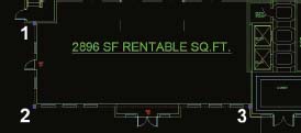
1. Open the AutoCAD file, ch04-01.dwg. This is the same drawing that was used at the beginning of Part 1 of this exercise.
2. Create a new layer called 0-Profiles, set its color to magenta, and set the current layer to this new layer. This will be the layer all wall profiles will be placed on. Using the prefix 0- helps with the organization of your layers, because it forces all the layers you create to appear together and at the beginning of the layer manager.
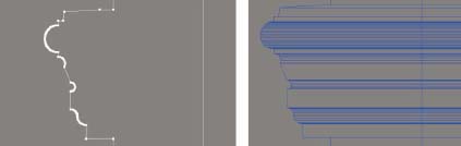
3. To the left of the front elevation, create a closed polyline representing the cross section of the main wall, as shown on the left in the next illustration. Since the exterior walls of a building are typically 8 inches thick, create the polyline 8 inches wide. You can either trace over the existing front elevation linework, or make a copy of the linework off to the side and use the various line editing features in AutoCAD to turn this copy into the closed polyline needed.

4. Create a new layer called 0-Paths, set its color to yellow, and set the current layer to this new layer. This will be the layer all wall paths will be placed on.
5. On the existing 1st floor plan, create a polyline representing the location of the exterior surface of the main wall, as shown by the 3 points in the next illustration.
At this point, we can import these 2 polylines into 3ds Max and create the main wall. Since there are 2 different file formats we can import, we have to decide which one will be used. If we use the AutoCAD DWG file type, we can simply import by layer and import only the 2 new layers we created. However, as mentioned several times in previous chapters, this format type often removes curves, and is therefore not always an option to be considered. The Legacy AutoCAD file type is always reliable and will therefore be the format type used here. Since we cannot import by layer with this option, and since we don’t want to import the entire architectural drawing every time we want to import new linework, we need to create a new drawing that only contains these 2 newly created polylines. There is a very quick and easy way to do this. Again, if you do not have AutoCAD these steps would not be necessary, as you will have already created your new linework directly in 3ds Max.
6. Select the 2 polylines you created in AutoCAD.
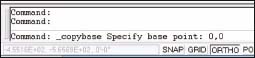
7. Right-click inside the viewport and select Copy with Base Point.
8. In the command line, type 0,0 for the base point. These last 2 commands copy the selected polylines to the clipboard using the origin as a base point.
9. Start a new AutoCAD drawing.
10. Type pasteclip in the command line, and type 0,0 for the base point. This pastes the 2 polylines into the new drawing.
11. Zoom to the extents of the drawing to insure that the new linework is in the drawing and save the drawing using the name wall_path&profile.dwg. This file would normally contain all of the paths and profiles that need to be created.
12. Close the file wall_path&profile.dwg and save the original AutoCAD file to the new name ch04-02.dwg. It is good practice to save your files incrementally so you can return to previous configurations of the same scene.
13. Reset 3ds Max.
14. Change the units of this new scene to U.S. Standard, Feet w/ Decimal Inches and with Default Units set to Inches. If you do not wish to work in U.S. standard you will have to convert the units prescribed in this exercise.
15. In the System Unit Setup dialog box, ensure that the System Unit Scale is set so 1 unit = 1.0 inches.
16. Import the file wall_path&profile.dwg using the Legacy AutoCAD file type with the derive by layer option, and use the Zoom Extents All command to see the 2 polylines (now to be called splines) as shown in the next illustration.

Before we can create the loft that will represent the wall we want to build, we have to set the pivot point of the wall profile spline. Since all splines we create or import have pivot points automatically created at their center, and since lofts use an object’s pivot point to determine the positioning of the loft, if we do not move the pivot point of the wall profile spline, we will end up with a loft half-buried in the ground. So at this point, we need to align the pivot point of the profile to the point that represents where the exterior surface of the wall meets the ground. But as mentioned in previous chapters, since the linework on our floor plan does not depict the trim that runs along the base of the walls but instead just the 8 inch concrete block, the true pivot point we need to establish would be where the exterior surface of the concrete block meets the ground.
17. Activate the Top view, and switch to a single viewport configuration of the Top view and perform a zoom extents.
18. Select the wall profile spline, and click and activate the Move transform.
19. Within the Hierarchy panel, click the Affect Pivot Only button.
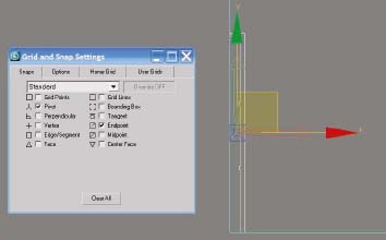
20. Change your snap settings so Pivot and Endpoint are the only 2 snap options enabled. Using these 2 particular snap options makes it easy to align pivot points.
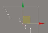
21. Enable snaps and place your cursor over the wall profile until the symbol for Pivot appears, as shown in the next illustration.
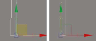
22. With the Pivot snap symbol shown, click and drag on the transform gizmo, and move your cursor to the very bottom-right corner of the wall profile spline, releasing the mouse button when the endpoint snap is shown on that corner (left side of next illustration).
23. Using the transform type-in, move your pivot point 8 inches in the negative X direction. If you made your wall spline 8 inches wide as directed in a previous step your pivot point should now be positioned exactly where the concrete block wall meets the ground, as defined by the exterior line you traced on the floor plan, and as shown on the right side of the next illustration.
24. Click the Affect Pivot Only button to end this command.
25. Change the snap settings so only the Endpoint option is enabled. This is the only option you will need for the majority of the time snaps are needed. When other snaps are needed, as in the example with the positioning of the pivot point, you can easily change your options when needed.
26. Disable snaps and switch to a Perspective view.
27. If you wish to continue from this point with an already prepared scene, open the file ch04-01.max.
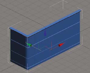
28. Select the wall path spline and loft the wall profile along its path. The result should look like the next illustration. If you created the wall path in the opposite direction from what was indicated in an earlier step your loft will be inside out. You will need to either go into spline sub-object mode of the wall path and reverse the direction of the spline, or create the loft again and hold down Ctrl when picking the wall profile in the viewport.
29. Switch to an Orthographic view and zoom to the extents of the loft. Switching to an Orthographic view makes viewport navigation much easier.
The first thing that needs to be corrected is the inappropriate smoothing 3ds Max automatically generates.
30. Go to the Modify panel and open the Surface Parameters rollout.
31. Disable the Smooth Length and Smooth Width options. With these options disabled, 3ds Max doesn’t try to automatically smooth corners and the shading looks more natural.
32. Enable Edged Faces mode for this viewport (hotkey=F4). This shows just how many unnecessary polygons are created by default.
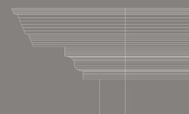
33. Switch to a Front view and zoom closely to the fascia and trim at the top of the wall loft, as shown in the next illustration. Notice that one area contains curves and everywhere else there are straight segments. These additional polygons are necessary to display the curved areas properly, but they are not at all necessary anywhere else. Because of this, it would be very wise to remove these additional segments created automatically, and manually tell 3ds Max where to place the additional vertices to make curves look smooth.
34. Within the Skin Parameters rollout, reduce the Shape Steps and Path Steps to 0. Notice that this causes the curved portion of the loft to no longer be curved.
35. Switch to a 4-viewport configuration and within the Top view zoom in closely to the top of the wall profile, as shown in the next illustration.
36. Select the wall profile and enter Segment sub-object mode.
37. Select the 2 curved segments (as shown in the next illustration) and within the Modify panel scroll to the bottom of the Geometry rollout.
38. Click the Divide button. Notice that the loft shown in Front view reflects the division of these 2 segments by adding additional polygons.
39. Click the Divide button two more times. Now the curved portion of the loft is quite smooth, as shown in the next illustration.
40. Repeat this process with the other curved segments found in the trim feature that runs between the 2nd and 3rd floors. Since each curved segment is different, consider dividing each segment a different amount. When finished, your trim should look similar to the following illustration.
Now your loft is perfectly optimized, with no more polygons than is necessary to create a great looking wall. You could reduce the polygon count even farther by removing the very bottom line segment in the profile, since no one would ever see this part of the loft. But for the few extra polygons you would remove, it’s hardly worth the trouble. You could even delete the inside wall segment, if the inside of the loft would never be seen, but again, the reduction in polygons would be insignificant.
One of the great things about the loft feature is how you can quickly incorporate trim, banding, and joint features into your loft by just including these details in the wall profile spline. We just accomplished in a few steps what took a very large number of steps to do in the previous exercise in Chapter 3. But before moving on to creating the windows for the 2nd floor of this wall, let’s make one more modification to the wall profile spline.
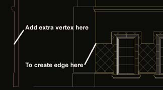
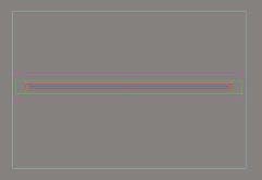
In the front elevation is a diamond shaped score pattern that runs along the wall and around the windows. If you analyze the building section, you will see that this is nothing more than a pattern set into the stucco that gets applied to the 8 inch concrete wall. Because it’s just a pattern, and not something like a banding feature that comes out from the main part of the wall, we can accommodate this pattern by simply using a different material for this portion of the wall. To add a different material to just this section of the wall, we have to first create the edges in the wall object so we can have separate polygons for the separate materials. And although we could use the Slice feature to add these edges as we did in the last chapter, we would have to add the Edit Mesh or Edit Poly modifier, and that would essentially break the link between the wall path and profile.
Instead of adding the Edit Mesh or Edit Poly here, we can again just modify the wall profile spline. This time, we simply need to add a vertex at the point along the wall profile that matches the same point on the front elevation where the change in material is indicated, as shown in the next illustration.
41. Refer back to the AutoCAD drawing and create a single line between the two vertical extremes of the portion of the wall that you need to add the edge, as shown in the next illustration.
42. Take a distance measure from the midpoint of this new line and the top of the scored wall feature. The distance should be 3.5 inches.
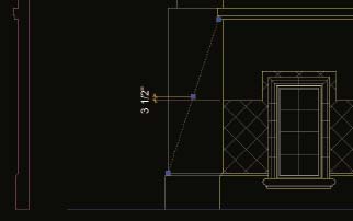
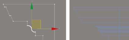
43. Go back into your 3ds Max scene, and while still in Segment sub-object mode of the wall profile spline, divide the appropriate segment once, thereby creating one new vertex in the very middle of the segment, as shown on the left side of the next illustration. Since we know that the top of the wall scoring occurs 3.5 inches below the midpoint of this segment, we can place this new vertex properly by moving it 3.5 inches in the negative Y direction.
44. Go to Vertex sub-object mode and move the newly created vertex 3.5 inches in the negative Y direction. If you look at the loft from a Front view, you will now see the additional edge created, as shown on the right side of the next illustration.

45. Close out of sub-object mode.
46. Save the file using a new name.
I always recommend saving incrementally and saving often, and before adding an Edit Poly modifier or creating a ProBoolean from the wall loft, it would be wise to save a copy of the scene first so you can come back to the scene in its current state, and pull objects like the wall loft out and modify them while the loft is still linked to the path and profile.
And speaking of linked objects, one of the great things we can do to our loft, because of its link to the wall profile spline, is quickly assign material IDs to the various polygons that make up the loft. By assigning material IDs to the various segments that make up the profile spline, the corresponding polygons on the loft receive the same material IDs. This means that we can quickly assign different materials to the loft or, at the very least, break the loft into separate objects by just selecting polygons by their different material IDs.
47. If you wish to continue from this point with an already prepared scene, open the file ch04-02.max.
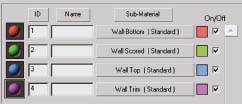
48. Open the Material Editor and create a Multi/Sub-Object material with 4 sub-materials. By looking at the elevations, you can determine how many different materials will be needed for the entire loft object. In this case, there are 4 distinct materials, as shown in the next illustration. Often you may not even be provided this information, at the modeling phase of a project, but it is nonetheless helpful to assign different material IDs to the different parts of a building so that when the time comes, you can easily assign those different sub-object materials or easily select polygons by their material IDs and detach the polygons to separate objects.
49. Assign different colors to each sub-material, as shown in the next illustration, so that the different parts of the loft stand out from each other when the material is assigned.
50. Assign the names shown in the next illustration to the 4 different sub-materials that will be applied to the loft. Any names will do of course, but I always like to stress to taking the extra few seconds to name objects and materials properly so scene navigation is as simple as possible.
51. Assign this new material to the wall loft. When you do, the entire loft should appear as sub-material color #1.
52. Select the wall profile spline and go to Segment sub-object mode.
53. Scroll to the very bottom of the Modify panel and open the Surface Properties rollout.
54. Create a window selection around the entire wall profile spline so all of the segments are selected. In the Set ID field of the Surface Properties rollout, you should see that all of the segments in the selected spline have material ID 1 assigned. This means that they will all receive sub-material 1 when a multi/sub-object material is assigned. If there is anything but the number 1 in this field, change it to read 1.
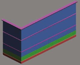
55. Change the material ID of the scored stucco region to 2, depicted by the green portion of the next illustration. Change the material ID of the rest of the stucco wall to 3, as depicted by the blue portion. Change the material ID of the 3 different trim features to 4, as depicted by the purple.
56. Close sub-object mode and save your scene.
Now that the different parts of the wall contain different material IDs, assigning different materials or breaking the wall into separate objects is quick and easy.
At this point, we need to continue with the creation and placement of windows and doors. This phase of modeling is best started once all of the walls are in place, because with all the walls created it’s easy to spot errors in your work, and fixing those errors won’t take as long as it would if you had already placed windows and doors inside the walls and broken the link between the loft and its supporting path and profile. So assuming that all walls are created at this point, we need to refer back to the AutoCAD drawings and prepare the necessary linework to create the windows and doors. Again, if you do not have AutoCAD, the same basic steps can be performed in 3ds Max.
As an additional note, it’s worth mentioning that while this chapter is dedicated to a demonstration of the Loft and ProBoolean combination, there is nothing preventing users from using the Loft and Edit Poly together or the Edit Poly and ProBoolean together. So if you feel that the Edit Poly is your best way to build walls, you can still make use of the ProBoolean to create the window and door openings and still use the procedures outlined in the remainder of this chapter to create the windows and doors that go in those openings.
57. Return to the AutoCAD drawing and make a copy of the rectangular window found on the 2nd floor and place the copy off to the side, as shown in the next illustration. Normally, this would be a copy of every door and window in the building, but since we are only concentrating on creating one window type, we only need to create this one copy here.

In time and with practice, all visualization artists refine what they feel to be an acceptable level of detail for the objects shown in a set of architectural drawings, but as mentioned before, if it’s important enough and sizeable enough to be shown in a set of elevations, then it probably needs to be shown in 3D. Likewise, if it’s not visible in the architectural elevations it’s usually safe to leave out of the visualization. Your contracts should even reflect this way of thinking.
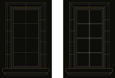
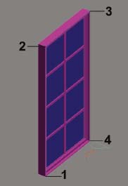
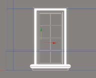
So in the case of this window, the lines shown in the elevations can be used to determine the level of detail we need to create. And without even looking at a window section or a window detail drawing, an experienced artist can take one look at the linework for the window and immediately determine what each line represents. To help facilitate your understanding of what the linework really indicates, the next illustration is provided as a reference.
In the real world, window and door assemblies are usually made up of dozens of different components, but in the 3D world, there are usually 4 major components that make up a window or door assembly. They are: frames, glass, trim, and the actual door or window. An additional object that will need to be created is the Boolean object with which to subtract the necessary void. If you break each window or door down to these separate elements, they are quite simple to create. In most cases, each component can be created by simply extruding or lofting splines.
One important note that goes back to what was said a moment ago about the level of detail needed, is that the drawings of these windows have, like most drawings do, the need for separate window components at different depths. What you should be able to discern from the last illustration is that very distinct parts of the window need to be created separately. The window frame is not just a couple of extrude splines, but rather a group of 3 distinctly separate components that once created are attached together. They are most easily created by extruding 3 separate sets of closed splines. Once extruded and positioned at their respective depths into the wall, they should be attached together because they will always require the same material.
Both the glass and the Boolean objects can also be easily created with extruded splines, while the window sill and trim features of this window can be easily created with lofts. So let’s continue now with the creation of these 2 windows with this basic understanding of the linework that makes up the window elevations.
The first element we will create the linework for is the window frame. First, let’s create the mullions and the 3 different parts of the frame that support them. If you do not have AutoCAD, use the equivalent 3ds Max features to perform the same steps.
58. Offset the single vertical line 0.5 inches to the left and right sides of the line. These 2 lines will be used to create a vertical mullion 1.0 inches thick. You can refer to a building’s section drawings to verify a mullion’s thickness, but a 1.0 thickness is a common thickness that seems most applicable to a window of this size. Even if the mullions needed to be less than 1.0 inches, I wouldn’t create them any smaller because mullions any smaller than this can begin to disappear at a distance and would often appear thinner than an individual pixel. It is common practice to thicken or enlarge certain object types to allow them to display better when rendered.
59. Offset the 3 horizontal lines 0.5 above and below just like you offset the vertical line. The linework should change from that shown on the left side of the next illustration to that shown on the right.
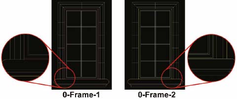
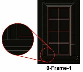
60. Create a new layer in AutoCAD called 0-Frame-1 and select the color magenta for the layer. This is the layer we will create the 1st frame linework on. The -1 suffix simply reminds us that this is the 1st part of the frame we are creating.
61. Make layer 0-Frame-1 the current layer, and using endpoint snaps, draw two rectangles that define the outermost frame component, as shown on the left side of the next illustration. If you do a distance measure of these 2 lines, you would see that they are 0.5 inches apart.
62. Create a new layer in AutoCAD called 0-Frame-2 and select the color green for the layer. This is the layer we will create the 2nd frame linework on.
63. Make layer 0-Frame-2 the current layer, and draw two rectangles that define the next frame component that lies just within the 1st linework you created, as shown on the right side of the next illustration. If you do a distance measure of these 2 lines, you will see that they are 1.5 inches apart.
64. Create a new layer in AutoCAD called 0-Frame-3 and select the color red for the layer. This is the layer we will create the 3rd and final set of linework on, which in this case is the mullions.
65. Make layer 0-Frame-3 the current layer and draw a single rectangle that represents the outer edge of the mullions as shown by the outer most red rectangle in the next illustration.
66. Using the extra linework you offset to create the mullions, and intersection snaps, create 8 additional rectangles defining the space between the mullions and the mullion frame. The result should be 9 total rectangles on this layer, as shown in the next illustration.
You should have just created 3 sets of lines on 3 different layers, and with 3 different colors (as a visual aid). In a moment, this linework will be imported into 3ds Max, extruded in different amounts and placed at varying depths.
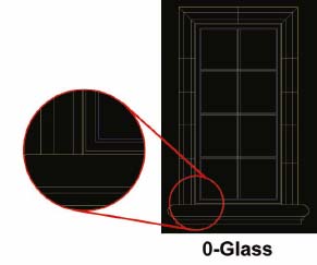
67. Create a new layer in AutoCAD called 0-Glass and select the color blue for the layer. This is the layer we will create the glass linework on.
68. Make layer 0-Glass the current layer, and draw a single rectangle that represents the location where the glass will be visible. This rectangle will be imported into 3ds Max and extruded a small amount. There is no need to create 8 individual rectangles for the glass even though there are clearly 8 window panels where the glass is visible. In the real world the glass would run through the mullions anyway, and we can allow this to happen in the 3D world as well since it saves time. The rectangle should look like the one shown in the next illustration.
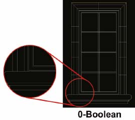
69. Create a new layer in AutoCAD called 0-Boolean and select the color cyan for the layer. This is the layer we will create the Boolean object linework on.
70. Make layer 0-Boolean the current layer, and draw a single rectangle that represents the outermost extent of the outer window frame. This rectangle represents the area that will be cut out of the wall, so this also needs to be co-located with the outermost rectangle you created for the window frame.
The next window object we’ll create is the window sill, and the method we’ll use is the loft. The only thing we don’t know about the sill’s structure by looking at the elevation is the depth of the sill; i.e., how far out from the wall it extends. Sometimes a section or detail drawing of these types of objects is not available, as was the case with this project. When information is lacking, an educated guess based on the rest of the building design can help, as can a call to the client. We can always change the depth later, but a good depth to start with is about 4 or 5 inches.
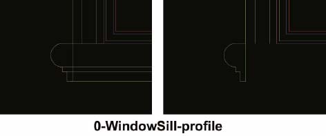
71. Create a new layer in AutoCAD called 0-WindowSill-profile and select the color green for the layer.
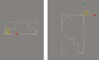
72. Make layer 0-WindowSill-profile the current layer, and draw a line down from the bottom left corner of the window trim to the bottom of the window sill, as shown on the left side of the next illustration. This will be the back of the sill that rests against the wall.
73. Using the line editing tools in AutoCAD (or 3ds Max), create a closed polyline from this new line and the existing sill linework, as shown on the right side of the next illustration. We won’t need the existing window linework anyway, so you can delete the unnecessary lines.
The last window object we’ll create is the window trim, and again, the method we’ll use is the loft. Like the window sill, there was no section or detail available for the trim. Unlike the window sill, we don’t even know for sure what the cross section looks like, but the light gray lines indicate that it is probably one of 2 different types; a curved or stair-stepped cross section.
74. Create a new layer in AutoCAD called 0-WindowTrim-profile and select the color red for the layer.
75. Make layer 0-WindowTrim-profile the current layer and use the existing linework to create the closed polyline shown on the left side on the next illustration. Rather than creating the curved portion shown in the illustration, we could have elected to create a stair-step shape with sharp corners, but based on the style of the rest of the building and the improved look the curve provides, creating the profile with this curvature is probably a good idea.
76. Move the newly created polyline off to the side of the window linework so that when imported into 3ds Max, it doesn’t interfere with our view of the other window linework we’ve created.
77. Save your AutoCAD or 3ds Max file.

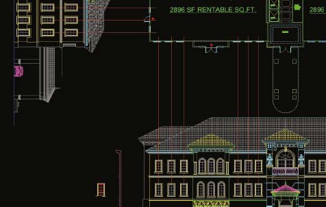
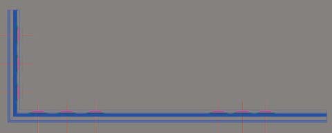
At this point, you would be finished with linework preparation of this window, whether your work was performed in AutoCAD or 3ds Max. If you were preparing the linework for every window and door in this building, the steps would be the same for every new window and door, and each assembly would be lined up in a row. For a larger building with far more window and door types, your lineup might look as long as the one in the next illustration, but if you perform the same steps for each assembly at the same time, you can dramatically reduce the total time needed to build each.
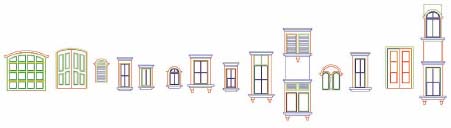
So with the linework for this single window completed, let’s complete this exercise by importing the linework into 3ds Max, turning the 2D linework into 3D models, and placing copies of the window in their appropriate locations around the wall we created.
78. Return to your 3ds Max scene (if you have preparing linework in AutoCAD).
79. If you wish to continue from this point with an already prepared scene, open the file ch04-03.max.
80. Hide all of the objects in your scene.
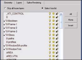
Unlike the last time we imported linework, this time we will try using the AutoCAD DWG file type, since it allows you to only import the layers you want, rather than the entire drawing. If for whatever reason you lose curves in your linework to the import process, you can always use the procedure demonstrated earlier whereby you copy and paste specific linework to a completely new drawing and use the Legacy AutoCAD file type to import the entire drawing. If you use the AutoCAD DWG file type, the next illustration shows the specific layers you need to import.
81. Using the AutoCAD DWG file type, import the linework on the 7 new layers you created. Make sure to use the option to derive objects by Layer, so all lines on the same layer become part of the same object. If you wish to use an already prepared AutoCAD file, import the drawing named ch04-02.dwg.
After importing, you should have the linework shown on the left side of the next illustration. The names of the linework should have the prefix Layer:, but for the purpose of calling out these new objects, this prefix will not be used in the naming of the objects.
82. Except for the 2 profile splines, rotate all of the window linework 90 degrees along the X-axis, as shown on the right side of the next illustration.

We now need to extrude each part of the frame, as well as the glass and Boolean objects. The amount that each needs to be extruded should be based on visual appeal when information about the true thickness is not available. Building and wall sections are not always available at the time our work needs to begin, as was the case with this project. Rather than bugging the client every time information is missing make an educated guess based on what simply looks best in a given situation. Asking a client too many questions can make you appear indecisive and inexperienced.
83. Extrude 0-Frame-1 in the amount of 4 inches, as shown in image 1 of the next illustration. This needs to be the largest extrusion amount since it will house the other parts of the frame. Knowing that our walls will be the normal 8 inches thick, you should make the largest frame component be at least a few inches thinner than the wall, but a few inches thicker than the smallest frame component; i.e., the mullions. 4 inches is the amount I always use here unless there is a definitive reason to use some other thickness.
84. Extrude 0-Frame-2 in the amount of 2 inches, as shown in image 2 of the next illustration. I always reduce each inner frame component to half the thickness of the next outer frame component, because it helps to show the separation between the two.
85. Extrude 0-Frame-3 in the amount of 1 inch, as shown in image 3 of the next illustration. Since we made the width of each individual mullion 1 inch earlier in this exercise, extruding this object 1 inch makes the mullions the same thickness in both directions. This is something to think about when you’re creating the mullion linework earlier in the process.
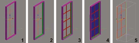
86. Extrude 0-Glass in the amount of 0.25 inches, as shown in image 4 of the previous illustration. You could always just convert this single rectangle to an editable mesh or poly; however, this might cause problems if you need to view this glass from the inside and do not make the glass 2-sided. Glass obviously has thickness in the real world, so there’s no real reason why you can’t give the glass thickness in the 3D world. The 0.25 value used here is a good arbitrary amount to use for glass.
87. Extrude 0-Boolean in the amount of 24 inches. This object only needs to be as thick as the thickest wall it will penetrate, but having it a bit thicker means that you don’t have to be as careful in its placement into the wall (in terms of depth).
88. With all 5 objects created, switch to a Top view and center each piece on each other along the Y-axis as shown in the next illustration.
89. Switch to an Orthographic view.
90. Hide the 0-Boolean object. This will allow us to see the other window objects.
91. Select 0-Frame-1 and attach the other 2 frame components to it (0-Frame-2 & 0-Frame-3).
92. Rename this window frame object Bldg-Frames. Renaming an object like this at this point is a good way to indicate that the object is structurally finalized and needs no other modeling work. You can use whatever prefix you like, but you should use some type of prefix that forces 3ds Max to list certain types of objects together. For example, when naming objects that make up a building, I always use the prefix Bldg-. This ensures that my frames, walls, glass, trim, and every other building object are listed together. If you had multiple buildings you would not have the frames of one building attached to the frames of another. In this case, I would name the frames of one building as Bldg1-Frames and the frames of another building as Bldg2-Frames. This makes scene navigation more efficient. When we create site objects in upcoming chapters, you will see that I recommend using the prefix Site-.
93. Rename the glass object Bldg-Glass. Incidentally, we do not need to rename the 0-Boolean object since it will disappear shortly when we use it with the Boolean command to create the openings in our wall.
94. In Orthographic view, draw a single spline around the very outside edge of the window frame beginning at the bottom left and ending at the bottom right, as shown in the next illustration.
95. In Top view, change the pivot point location of both the 0-WindowTrim-profile and 0-WindowSill-profile objects, as shown in the next illustration.
96. Divide the curved segment in each spline enough to allow for smooth curves in the loft.
97. Loft the 0-WindowTrim-profile around the spline you just created around the window.
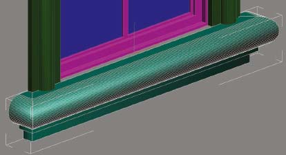
98. Disable Smooth Length and Smooth Width and reduce the Shape Steps and Path Steps to 0. Your loft and its placement should look like that shown in the next illustration.
99. With this object being structurally finished, rename it to Bldg-Trim1.

100. Using the bottom of the newly created loft as a guide, create a spline with 4 vertices, starting from the top left and ending at the top right as shown in the next illustration.
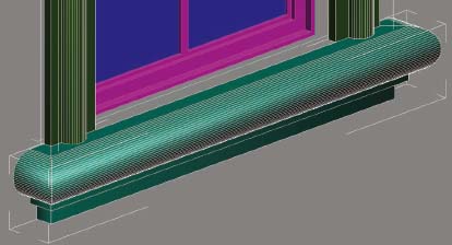
101. Loft the WindowSill-profile along this newly created spline.
102. Disable Smooth Length and Smooth Width and reduce the Shape Steps and Path Steps to 0. Your loft and its placement should look like that shown in the next illustration.
103. With this object structurally complete, rename it as Bldg-Sills.
104. Move the WindowSill and WindowTrim objects 2 inches in the negative Y direction, as shown in the next illustration. Since the window frame is 4 inches thick and the wall it lies within is 8 inches thick, there should be 2 inches between the window frame and the outside surface of the wall, which is where both the trim and sill will be placed.
With this last step, our window is complete and ready for placement around the wall.
105. Unhide the 0-Boolean object.
106. Select the 0-Boolean object, right-click inside the active view, and within the Object Properties dialog box, enable the See Through option to make the 0-Boolean object transparent.
107. Create a group named Window-A containing all of the window objects (Bldg-Frames, Bldg-Glass, Bldg-Sills, Bldg-Trim1, and 0-Boolean). Since you would normally be creating multiple window types, this type of name will help you quickly distinguish the group from other window types (if necessary).
108. Save the file.
109. Return to your AutoCAD file (if using AutoCAD). You can also just use the file name ch04-02.dwg.
110. Create a new layer called 0-Window&DoorGuides and select the color red for the layer.
111. Make 0-WindowDoor&Guides the current layer and using the front elevation, draw vertical lines from the center of each 2nd floor window we are placing, upward through the front wall on the floor plan. You should create a total of 6 vertical lines, as shown in the next illustration.
112. Using the left elevation, draw horizontal lines from the center of each 2nd floor window we are placing, to the right, until you cross the left side wall on the floor plan. You should create a total of 3 horizontal lines as shown in the next illustration.
113. Save the file.
114. Return to your 3ds Max scene or continue with the file named ch04-04.max.
115. Import the 0-WindowDoorGuides layer. You can also import this linework from the file ch04-03.dwg. These 9 lines can now serve as a guide by which to place copies of the window you created.
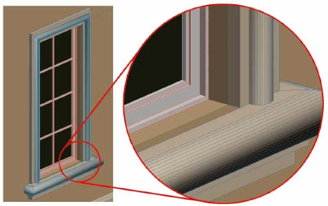
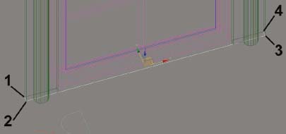
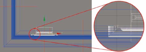
116. Using Top view, make an instance of the 3D window assembly you created and position it inside the wall loft, as shown in the next illustration, using the linework you just imported as a guide. The window frame should be approximately 2 inches from the inside and outside wall surfaces. If you import the linework using the Entity option (so that each spline is a separate object), you can use the Align command to position each window to its exact position. However, this type of object does not need to be placed with such precision along the length of a wall. Eyeballing it is perfectly acceptable in this type of situation. However, since the trim and window sill needs to be not floating in mid-air, you must ensure that it is positioned against the outer face of the wall or just slightly inside, as shown in the blow-up of the next illustration.
Now we have to position the window at its correct elevation. Before we can do so, we should align the very bottom of the window sill with the ground and then measure the distance the assembly needs to be elevated.
117. Using Front view, move the window assembly so that the very bottom of the sill object is aligned with the ground, as shown in the next illustration.
118. Refer back to the AutoCAD drawing and measure the distance from the ground to the very bottom of the window sill, as shown in the next illustration. The distance should be measured at 14’-8.5”.

119. Switch back to your 3ds Max scene and move the window assembly up 14’-8.5” in the Z direction (as seen from a Top view).
120. Create 8 additional instances of this window group and use the window guidelines to position them in their proper locations, as shown in the next illustration.
121. Save the file and save it again under an additional name. Since the window groups were created as instances, if you need to change the window design you can change one and have each update automatically. Saving the file to an additional name means that you can continue working on the building, but come back to the building in this current state to modify the windows while they are still instances and then merge them into a later version of the scene.
122. Select all 9 window groups and ungroup them.
123. Deselect all of the objects and select any one of the 9 window frames.
124. Collapse this object to an editable mesh or editable poly. This is very important, because if you don’t the next step won’t work.
125. Attach all of the other 8 window frames to this object. In this exercise, we are only working with 1 window type, but normally, all window frames from each window type would now be one single object.
126. If the name is not already correct, rename the window frame as Bldg-Frames. When instances of the object were made, a suffix was added.
127. Repeat the process of attaching similar objects together and renaming them. Do not forget to attach the Boolean objects together.
At this point, we need to subtract the Boolean objects from the wall loft to create the window openings.
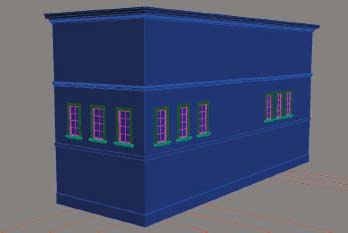
128. Select the wall loft and use the ProBoolean command to subtract the 0-Boolean object from the loft. The result should be a wall loft with 9 openings in it, as shown in the followng illustration.
129. Save the file. If you wish to see a completed version of this scene, open the file ch04-05.max. This concludes the exercise.
Wall Materials
Since this chapter and the previous ones were a discussion on creating walls, now would be a good time to say a few words on material selections for these objects. Advanced material creation will be discussed in later chapters that deal with mental ray, but I want to mention a few things that come up constantly in discussion forums and intermediate level classes we teach.
There are just a few types of wall materials you will need to simulate in a typical visualization; concrete, brick, stone, and aluminum or wood siding. There are a few other less commonly used wall surfaces you might need to simulate on occasion, such as the logs of a log cabin, but the majority of wall surfaces you will need to simulate fall into one of these 4 categories (not withstanding the use of glass as a primary building surface material). Some of these wall surface types should clearly be created with maps loaded in the Diffuse Color channel, while others should be created by use of maps loaded in the Bump channel. In addition, under certain conditions, the Displacement channel can be used to enhance the 3D appearance of a material type.
Use of the Bump channel
When concrete is the visible exterior surface material of a wall, it usually comes in the form of stucco or CMU (concrete masonry unit). When stucco or some other poured type of concrete is needed, rather than applying an image in the Diffuse Color channel of a material, you should simulate the material with a map loaded in the Bump channel and leave the diffuse color channel empty so you can quickly change your wall color without having to update an image. The left image in Figure 4-1 shows an image of a beige stucco wall. This image could certainly be loaded into the Diffuse Color channel, but if you or the client wants to change the color of the wall stucco to green, then you would need to use Photoshop or some other photo editor to change the color and resave the file, or save to a new file and load the new bitmap in 3ds Max. This can get old quite fast. There are other difficulties you might also run into, such as the image appearing too tiled or too blurred when viewed up close.

Figure 4-1. Images of stucco manipulated in Photoshop to allow for color changes.
Rather than simulating stucco this way, you should use a map loaded in the Bump channel to simulate the texture you want and change the wall color with the Diffuse Color channel. The stucco texture shown in the left image of Figure 4-2, for example, was created by loading the black and white image shown on the right into the Bump channel. This allowed us to quickly change the color of the wall as well as create multiple wall colors, as shown in the rendering, without ever having to leave 3ds Max or manipulate the original image used. Creating a texture like this makes it possible to zoom in very close to the wall without creating a blurring effect for the image’s lack of resolution. It also becomes easier to prevent a tiled appearance using an image in the Bump channel.

Figure 4-2. Different stucco colors created with a single black and white image loaded in the Bump channel.
Creating wall texture this way has another unique advantage. Because the image loaded in the Bump channel is a bitmap, which is a 2D map (as opposed to a procedural 3D map), you have to control its scale through the use of a UVW Map modifier. However, you can control the strength of the wall texture (i.e., its roughness) by adjusting the bump amount. This is something you cannot do if you load an image of stucco (or any other wall surface image) in the Diffuse Color channel.
In addition to creating stucco this way, you can quickly create patterns in your wall surfaces, such as the diamond-shaped pattern shown on the wall in Figure 4-2, which was created by the left image shown in Figure 4-3. The right image of Figure 4-3 could be used to simulate an exposed CMU wall.
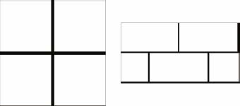
Figure 4-3. More black and white images that can be used in the Bump channel to create a unique wall pattern.
In addition to creating stucco this way, you can quickly create patterns in your wall surfaces, such as the diamond-shaped pattern shown on the wall in Figure 4-2, which was created by the image shown in Figure 4-3.
Use of the Diffuse channel
When you need to create a brick, stone, or wood wall surface, such as those shown in Figure 4-4, you simply cannot avoid using an image of such a material in the Diffuse Color channel. You can certainly enhance its 3D appearance with the use of an image in the Bump channel, but there is simply no getting around the need for these types of images. This is especially true if you’re trying to simulate additional material qualities such as chipped paint, rust, or other weathered appearances.

Figure 4-4. A brick, stone, and wood image that would be suitable for use in the Diffuse Color channel of a material.
Use of the Displacement channel
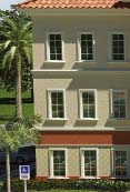
Many types of material surfaces can be given a noticeable 3D enhancement through the use of displacement. This type of enhancement, however, often comes with an expensive price tag. Using displacement to make the material on a wall appear more 3D can dramatically increase rendering time, but unless the view is extremely close to the wall with the displaced material, it’s rarely worth it. The siding shown on the building in Figure 4-5, for example, was created using the black and white striped image shown in the upper left corner of the image. Had displacement been used, there would be no discernible improvement in the 3D look of the siding. However, if the view were much closer, say from the patio, then the use of displacement might be noticeable, and therefore, justified. In reality, even if the use of displacement were justifiable, I would prefer creating the 3D appearance of the siding manually by physically building the relief into the walls. The loft is a great way to do this with little effort.

Figure 4-5. An example where the use of displacement would be unjustified to enhance siding on walls.
Using displacement on a brick wall would be even more difficult to justify, because unlike siding, the displacement would run both horizontally and vertically. And unless you are using an advanced render engine such as V-Ray, you are going to need to have the polygons in place ahead of time to allow for displacement. With V-Ray, you can create a great-looking displacement for a brick wall (or any other material), even when you only have 1 polygon in place. With most other render engines, you have to have many thousands of additional polygons in order to create a good looking displacement. For all of these reasons, the need for displacement on walls is rare.
Summary
This chapter was a demonstration of the power and efficiency of the Loft and ProBoolean combination. Like most areas of modeling, there are usually numerous ways to arrive at the same result. However, this particular method of work, I believe, is an example where there is clearly a best solution. With good linework in place, regardless of whether the linework is prepared in AutoCAD or 3ds Max, creating walls can be quick and easy. If you save your work incrementally and often, you can also return to an earlier version of your scene to recover your wall lofts or window Booleans in their original state, and use the power and flexibility of both features to make drastic modifications with ease. Creating walls is not difficult, but because it can be so time-consuming, this is one area of scene creation that you should make sure you are maximizing efficiency.