
CHAPTER 7
Creating 2D Sites
IN THE LAST FOUR CHAPTERS, we covered the creation of building elements such as walls, windows, doors, and roofs. This chapter begins a four chapter series discussing the creation of objects that can be generally classified as site elements, such as roads, sidewalks, curbs, backgrounds, and vegetation. In this 1st chapter, we’ll look closely at some of the best techniques for creating 2D sites, and in the next chapter we’ll use many of the same tools and numerous others to create 3D sites. The remaining two chapters deal with the challenges of creating realistic backgrounds and vegetation.
Creating a 3D site plan can seem like a daunting challenge and can easily frustrate experienced users. For many years, 3DAS has experimented with virtually every possible way to create site plans, and if you’ve been frustrated with a particular plan of attack, there’s a good chance that we have probably experienced a similar frustration when trying the same thing. We now find ourselves using the same steps and the same tips and tricks on just about every site we work on, with minor variations in site elements specific to each piece of work. With a little practice using these routines, anyone can breeze through constructing a solid 2D site in minimal time.
This tutorial covers the creation of some of the most prevalent types of objects found in site drawings. Specifically, each of the following object types are included:
• Grass
• Roads
• Curbs
• Sidewalks
• Pavers
• Paver bandings
• Road lines
• Mulch
• Parking stops
Obviously, any given scene may need to be populated with miscellaneous object types such as cars, people, signs, etc.; however, these objects should be pulled from your pre-existing libraries and not created from scratch. Vegetation and backgrounds can also be considered site objects but will be discussed in depth in Chapters 9 and 10.
In this tutorial, we wanted to demonstrate as many tips, tricks, and routines as possible, spending minimal time on repetitive steps that waste time without teaching anything new. Therefore, the site plan used in this tutorial may appear overly simplified. For example, lines that represent streets are often poorly constructed and contain countless breaks, rather than being continuous lines. Rather than giving you lines that require hours of editing and welding to fix, we have provided nearly perfect AutoCAD linework, with only a few imperfections that allow us to demonstrate problems usually commonplace to site drawings. This will allow the tutorial to progress rather quickly in comparison to real-world site creation, and therefore speed up and optimize learning considerably.
One additional note about this and all future chapters is that by this point in the book, many of the commands featured have been discussed numerous times before. Because of this, most of the chapters from this point on will usually explain previously discussed commands only once at the 1st instance of the command and will assume that you know how to find and implement those commands after the 1st instance.
The Metro Professional Complex
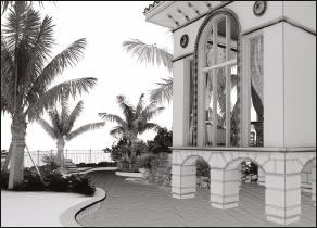
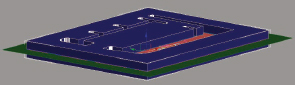
For this exercise, we return to a past project that, at the time of the writing of this chapter, is still under construction in the business district of downtown Fort Lauderdale, Florida. This project is a medium-sized modern commercial building development and the final product called for two high resolution renderings with views of the front and rear of the building, as shown in Figure 7-1. This project consists of a single 3-story contemporary building, with a parking lot that extends around and underneath the building, and a courtyard in the front containing a fair amount of vegetation.

Figure 7-1. Two finished images of the Metro Professional Complex.
I always like to visit a project’s site whenever possible to get a feel for the property and its surroundings at the time of day I think I would like to create the images. A helpful tool in the study of a site, especially when you cannot visit it in person, is aerial and/or satellite imagery, such as the left image shown in Figure 7-2. Any photographs the client can provide, such as the right image, are also invaluable.

Figure 7-2. A old satellite image and new street level photo of the project site just before construction.
Some of the best satellite imagery can be found through Google Earth and Microsoft Virtual Earth. If you haven’t already investigated these applications, as well as professional versions of both you would be doing yourself a favor to do so. One particularly useful feature in Microsoft Virtual Earth is the ability to view aerial imagery from a perspective view. Figure 7-3 shows an example of this. If you’re lucky enough to have your project located in one of the areas where such library photography is available, you can truly enhance your ability to visualize the surrounding environment.

Figure 7-3. An example of Microsoft Virtual Earth.
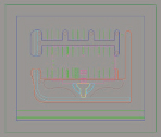
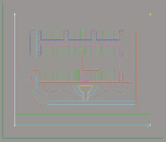
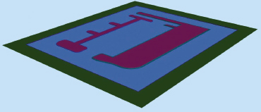
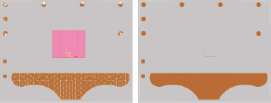
So the first step in the creation of a 3D site plan is to ‘clean’ the drawing and prepare it for use in 3ds Max per the guidance outlined in Chapter 2. The original site drawing, shown in the left image of Figure 7-4, was actually one of the cleanest site drawings I have ever worked on, yet it still contained most of the problems discussed in Chapter 2, which required about 1 hour to clean. There was extraneous information that needed deletion, such as setbacks, dimensions, survey lines, etc., and most of the useful linework consisted of individual lines rather than continuous polylines. Nearly every line needed attention, but nonetheless, the linework was overall simple to use and easy to understand. Once completed, our cleaned site drawing looked like the right image in Figure 7-4.

Figure 7-4. The ‘dirty’ and ‘clean’ AutoCAD site drawing for the Metro Professional Complex.
An important note to make about the cleaned site drawing is that some liberties were taken in the creation of linework not shown in the original site drawing. Notice in the cleaned version that there are two rectangles placed around the outside of the property. The outside rectangle represents the terrain (referred to in this exercise as the grass) and is the limit of what will be seen in any view. The second rectangle is a line we will use to create curbs. Although this rectangle does not appear in the original site drawing either, and although curbs would never enclose a property in the real world, it was placed here for two reasons. First, we know that we will need a single rendering of the front and back of the property and that our vantage points will not show the fact that the curbs are completely surrounding the property. Second, this same line will be used to cut out the roads from the surrounding grass object created by the first rectangle. I also wanted to show some road lines in the rendering that did not appear in the original site drawing. This is why you can see the three green lines in the cleaned drawing that do not appear in the original. The ultimate goal in adding this additional linework is to create a reasonable grass, road, road line, and curb object as shown in the final renderings in Figure 7-1. For these reasons, we can take the liberty of creating linework in a manner that would not be practical in the real world.
Since the 2D linework is prepared, we can begin the creation process for each of the elements that will make up the 2D site. It is important to note at this point that the linework to be imported into 3ds Max can be imported all at once or one layer at a time. In this tutorial, I chose to import all linework at the same time; however, this is a matter of personal preference and in more complex sites I recommend importing one layer at a time. This will allow you to work on one site element at a time and not clutter your view and workspace with linework you are not currently working on. More importantly, it gives you time to get a ‘feel’ for the project and to think about how to create the more difficult elements later while working on some of the easier elements.
Before going any further, I would like to reiterate a point made in Chapter 2 about the origin of a file. If you look in the original drawing, metro_initial.dwg, you’ll notice that the origin is located a great distance away from the linework of this project. In the cleaned drawing I moved all of the linework in the project so it is centered on the origin. This is important because, unlike AutoCAD, the accuracy of 3ds Max is greatly dependent on where you operate in the world-space coordinate system. If you are not familiar with why this is or are not completely confident with how to set up the 3ds Max work environment, please refer to the discussion in Chapter 2.
Import the linework
When you prepare linework in CAD, it is important to figure out ahead of time which scene elements are going to be combined into the same scene objects. Minimizing the number of object types will reduce the number of times you have to perform the same 3D operations in 3ds Max and can greatly improve speed and efficiency. For example, if you had dozens of parking lines on several different layers, it wouldn’t make sense to import those lines and apply the same commands to each of those separate objects in order to turn them into renderable meshes. It would be better to place all of the parking lines on the same layer so you only have to prepare the one object.
In this project, I have simplified the AutoCAD drawing so that only 13 unique layers exist besides the default 0 layer, as shown in Figure 7-5. This makes turning the linework into a finished site much easier. I like to retain very strict layer management to aid efficiency and workflow. I give all my layers very descriptive names so there is no doubt what is contained on them and I go to great lengths to ensure that all linework is placed on the appropriate layer. Notice also that all the layers are preceded with the prefix 0-. This is a personal technique I use to keep my own layers at the top of the layer manager. When the site is completely cleaned of any unnecessary layers, it’s a mute point; however, during the cleaning process, this is a very useful technique that helps navigating around what is sometimes hundreds of layers. I also categorize my layers by giving them an additional prefix, such as Site or Bldg, which allows me to quickly and easily locate and isolate all my building or site linework in AutoCAD as well as in 3ds Max.
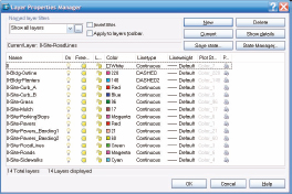
Figure 7-5. The project layers created in AutoCAD.
Now that everything possible has been done to streamline our work in 3ds Max, let’s go ahead and import the linework.
1. Reset 3ds Max.
2. Set units to U.S. Standard, Feet w/ Decimal Inches, and Default Units to Inches.
3. Make sure the System Unit Setup dialog box shows that 1 Unit = 1.0 Inches.
4. Import the file metro_clean.dwg using the Legacy AutoCAD file type and the default options, Derive Objects By Layer and Convert to single objects. The Group common objects option should not be enabled.
5. Zoom to the extents in each viewport and turn off the home grid in each. Disabling the home grid makes seeing the linework a little easier.
6. Activate Top view and switch from a 4-viewport to a single viewport configuration. The scene should look like the following illustration.
Grass
The first important rule in creating terrain is to ‘keep it simple’. Almost no site in the real world is completely flat, and therefore, when you receive a drawing originating from a surveyor or some other type of civil engineering firm, chances are pretty good that you will find notes or topographical lines indicating some variation in the elevation of the terrain. However, when looking through the lens of a camera, whether in the real world or in the virtual world, you will often not see the subtle variations in elevation that would justify the use of 3D terrain. For instance, if a parking lot had a 6 inch downward pitch toward its center to allow for water to flow into a drainage feature, this is something you should never have to worry about modeling. Creating this simple little change in elevation can bring about a number of different problems that would otherwise not have to be addressed if the parking lot were to remain completely flat. In this scenario, one would have to ensure that the parking lines conformed to the slope of the parking lot and that cars were positioned just right so their tires weren’t seemingly buried in the pavement or floating a few inches above it. For such small variations in terrain, it is far better to avoid the complication of accommodating this kind of detail. In the next chapter, we’ll cover some of the many different ways of creating 3D terrain, but for this particular site we are going to simplify things and create the terrain as a flat piece of land.
7. Enable endpoint snaps and use snaps to draw a rectangle directly on top of the second rectangle from the outside (0-Site-Curb_B.01), as shown in the following illustration.
8. Name the object Site-Grass_Outside.
9. Add the Edit Spline modifier and attach the object named 0-Site-Grass.01 to this new rectangle you created.
10. Add the Edit Poly modifier to this object and render Top view. Your rendering should look like the left image in the following illustration. This object represents the grass that surrounds the roads.
11. Use snaps to draw a 2nd rectangle in the exact same location as the 1st.
12. Name this object Site-Roads. This object will be the foundation of the road that will be created.
13. Add the Edit Poly modifier to this object and render Top view again. The result should look like the right image of the following illustration.
14. Disable snaps.
15. Save your file.

Curbs
There are numerous types of curbs used in the real world, but in this project only two unique types are called out. For the sake of simplicity, I have labeled these curb types as type A and type B, as shown in Figures 7-6 and 7-7. These two types are perhaps the most widely used in the world and even when a project calls for a slightly different appearance, these two types can usually be relied on to fill your needs.
In this project, type A has an overall cross-section width of 2’-0”, which includes a 6-inch wide raised portion that retains the surrounding topsoil. Sometimes referred to as a gutter curb, this type of curb is beneficial for allowing rain water to drain into the various drainage basins. It’s used along one side of the main road that runs in front of the property and wraps around the front half of the building in a continuous closed fashion.
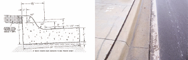
Figure 7-6. Curb Type A.
Type B is a curb with a simple rectangular cross-section and an overall width of 6 inches. This curb type separates the grass from the road in some areas and the pavers from the road in other areas. It is used around the small island under the backside of the building, but will also be used outside of the property limits to improve the appearance of the rendering.
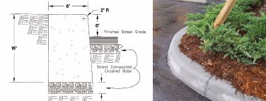
Figure 7-7. Curb Type B.
The first curb we will create is Type A, which runs along the main road in front of the property and around the front half of the building. This type of curb is usually represented by three lines, and the drawings for this project make no exception to this. The inner line closest to the grass represents the back side of the curb, the middle line represents the top outside part of the curb, and the outside line closest to the road represents the point where the curb meets the road.
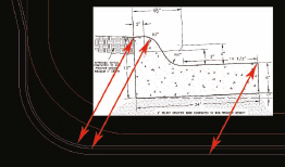
Figure 7-8. A plan and section view of one of the project’s curb.
The first thing to decide is what type of method you’re going to use to model the curbs. For most curbs, the Loft command and Sweep modifier cannot be beat. You can always use techniques such as a renderable spline with a 4-sided cross section or an extruded closed spline, but nothing compares to the power and versatility of the Loft and Sweep. With these tools and good linework in hand, you can create curbs for the largest of scenes in just a few minutes. As a matter of personal preference, I prefer the Loft command because of how it respects a profile’s pivot point; however, since you cannot loft along a path consisting of non-continuous splines, the Sweep modifier is the better tool for larger scenes. This is a very small scene that will take the same amount of time either way, so in this exercise we will use the Loft.
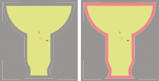
The first step is to create a shape that represents a cross-section of the curb and a path with which to loft the shape along. The shape I created for this curb, shown in Figure 7-9, is a simplified version of the curb section shown in Figure 7-8. This curb is 6 inches tall, 24 inches wide, and contains two curves with a 2-inch radius.
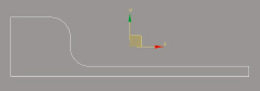
Figure 7-9. The shape to be lofted with the pivot point centered on the shape.
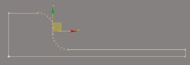
Before you can use any shape for a loft, you have to adjust the shape’s pivot point so that the loft is created in the appropriate place in 3D space. As a rule, I always establish my roads at an elevation of zero (i.e., aligned with the home grid), and most other objects tend to be at an elevation at or above this point. In Figure 7-9, you can see that the pivot point is located at the center of the object. However, this is not an appropriate place with which to align a loft in 3D space because the center of the loft will be aligned with the home grid, and therefore, the bottom half will be below the roads.
So once your shape is created and selected, open the Hierarchy panel, select Affect Pivot Only, and use the Align command to move your pivot point to the bottom left corner of the object, as shown in Figure 7-10. If you wish to use this same shape in creating the curb for this project, use the file named shape-curb-A.max when we continue with the exercise in just a moment.

Figure 7-10. The shape to be lofted with the pivot point aligned properly.
As I mentioned before, in the original drawing (metro_initial.dwg), there were three lines that represent the structure of the curbs, yet in the cleaned file (metro_cleaned.dwg), notice that only one line exists. This is because only one line is needed to loft the shape and anything else brought into 3ds Max would be unnecessary and only serve to clutter your workspace. The line I chose to use as the path for the loft is the inside line where the curb meets the grass. The reason I chose this line is that after we prepare it for lofting, it can be used later to cut the grass out of the road. If we used any other line, then we cannot apply displacement to the grass without having the grass appear to be growing up through the curbs.
Let’s continue creating our curb:
16. Continue from the previous exercise or open the file ch07-01.max.
17. Merge the curb shape you created or the one found in the file shape-curb-A.max. Notice that the shape is merged into your scene at the scene origin. I placed the shape at the origin for convenience in locating it later.
18. Select the object 0-Site-Curb_A.01. This object will be used to create curb Type A, and be one of the lines used to create the road the curbs run along.
19. In the Command panel, select Create > Geometry > Compound Objects > Loft.
20. Click the Get Shape button and click on the shape you just merged.
21. Switch to a Perspective view and then change the view to an Orthographic view. Switching to an Orthographic view makes viewport navigation much easier, and switching to Perspective view first is necessary to keep from simply making the Top view an Orthographic view.
22. Enable Edged Faces. The Orthographic view should already be set to Smooth+Highlights.
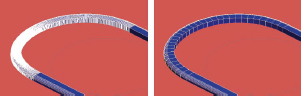
23. Zoom in closely to one of the curved areas of the curb. Notice two things wrong with the object, as shown in the left image of the following illustration. One is that the gutter portion of the curb is on the inside rather than the outside. The other is that the curb appears chiseled rather than smoothly curved. Let’s fix the first problem and come back to the second later.
24. Undo the Create Loft command.
25. With the object 0-Site-Curb_A.01 still selected, enter Spline sub-object mode and within the Geometry rollout, click the Reverse button. This reverses the direction of the spline, which causes the loft’s shape to be projected in the opposite direction.
26. Create the loft again. Having reversed the direction of the path, the curb object is now created so that the gutter is on the outside, as shown in the right image of the following illustration.

The second problem with the object is that it appears chiseled in all of the curved areas. This is because there are not enough vertices in the original path, and not enough default steps used when the loft was created. You could increase the number of steps in the loft above the default value of 5 to achieve much smoother curves, but there are two problems with this strategy. One is that there will be unnecessary faces created in straight segments where additional steps are unnecessary. The second is that by the time you increase the path steps high enough to allow for smooth curves, you will see overlapping faces and erratic shading in corners. Both of these problems can be seen in the following illustration where the path steps were increased to 10. The solution to both of these problems is to globally reduce the number of steps to 0 and manually insert the steps where needed.
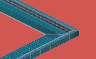
Figure 7-11. The curb object lofted with 10 steps.
27. With the loft selected, open the Skin Parameters rollout in the Modify panel and reduce the Shape Steps and Path Steps value to 0. Notice that the loft loses all its curves along both its cross section and along the path. This ensures that there will be no unnecessary faces along portions of the loft that should be completely straight. Now let’s add faces where they are needed.
28. Select the object 0-Site-Curb_A.01 and enter Segment sub-object mode.
29. Switch to Top view and zoom into the top right corner of the object, as shown in the following illustration, and select the two curved segments of the spline.
30. In the Modify panel, scroll down to the bottom of the Geometry rollout and click the Divide button. Notice that the highlighted segments are divided into 2 segments of equal length.
31. Click the Divide button again. The 2 segments of each curve are now divided into 4 segments of equal length and a curve is reappearing in the loft. Continue to click the Divide button until this portion of the loft achieves a reasonable level of curvature, as shown in the right image of the following illustration.
32. Repeat this same process with each portion of your loft that should be smoothly curved. You can highlight multiple segments of the path and divide those segments at the same time and to better see the segments you want to highlight, delete the loft and recreate it once the path is structured properly.
In addition to the path, the shape needs to contain an adequate number of vertices in the curved segments.
33. Select the shape Shape-Curb_A, zoom in closely in Top view and enter Segment sub-object mode.
34. Select the two curved portions of the shape and divide these segments with a segment value of 6, as shown in the following illustration. This will provide smooth enough curves without too many unnecessary vertices. If this were a much larger project where the typical view would be much farther away from the curbs in your scene, you could easily get by with just a few additional segments added.
35. Close sub-object mode.
After completing the corrections to your path and profile, one final modification you should make to your loft at this point is to improve the smoothing.
36. Switch to Orthographic view, select the loft object, apply the Smooth modifier and enable the Auto Smooth option. To see the effect of this modifier, look around at different parts of the object while toggling this modifier on and off. You will see the shading change significantly in some areas. Although lofts automatically have the Smooth Length and Smooth Width enabled, this is usually a bad thing and results in a bad appearance around corners. The Auto Smooth option fixes this problem.
As a matter of practice, I recommend changing the name of your objects once their structure has been finalized, and having finalized the structure of this object, now would be a good time to rename it.
37. Change the name of your loft to Site-Curb_A.
38. Save your file.
Now we need to create curb type B, which surrounds the small island at the rear of the property and is also used around the roads that surround the property. Because of the structure of this particular curb type and how the linework was developed, this curb should only take a few quick steps to create.
39. Continue from the previous exercise or open the file ch07-02.max.
40. Select the object 0-Site-Curb_B.01.
Since we used the loft command last time and since this 2nd curb object consists of more than one spline that would have to be lofted individually, here we’re going to use the Sweep modifier. Knowing this, we should prepare our curb linework ahead of time. I always prefer to divide the segments before creating a loft or sweep so the spline can be seen without being obscured.
41. Switch to Top view and zoom to the extents of the scene.
42. Enter Segment sub-object mode and divide the curved portions of the curb object into an adequate number of segments, just as we did with curb Type A. Exit sub-object mode when you are finished.
Now we need to create a shape to sweep along the path of this object. After you create this object once, you should save it in a library of objects so you can retrieve it later rather than creating it all over again.
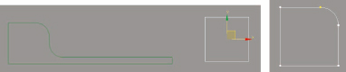
43. Zoom in to the origin of the scene where the Shape-Curb_A object is located and draw a rectangle with an approximate length and width of 6 inches, as shown in the left image of the following illustration.
44. Go to the Modify panel and change the length and width of the rectangle to exactly 6 inches.
45. Open the Interpolation rollout and change the Steps value to 0. If this is not done the resulting sweep will have all of these additional steps built into its cross-section. When creating sweeps, it is much better to manually create the additional vertices as needed, just as we did with the path.
46. Add the Edit Spline modifier.
47. Enter Vertex sub-object mode and select the top-right vertex.
48. Within the Geometry rollout, type 2 inside the field to the right of the Fillet button and press Enter. The corner changes to incorporate a 2-inch chamfer, assuming you reduced the interpolation steps of the rectangle to 0 just a moment ago. If you didn’t reduce the steps you would see a 2 inch curve, as shown in the right image of the following illustration. To actually get this curve to appear now, we need to divide this segment several times. This will provide the proper look to the top corner of the curbs closest to the roads.
49. Enter Segment sub-object mode, select the 2-inch fillet segment (which really looks like a chamfer presently) and divide it with 6 segments. A decent curve should appear.
50. Rename the object Shape-Curb_B.
Since we are going to use the Sweep modifier, we don’t need to adjust the object’s pivot point.
51. Select the object 0-Site-Curb_B.01 and apply the Sweep modifier.
52. Within the Section Type rollout, enable the Use Custom Section option, click the Pick button and click on the Shape-Curb_B object in the viewport.
53. Switch to Orthographic view and zoom in closely to one of the curved portions of the curb object. Notice that this curb is also inside out.
54. Go down in the modifier stack to the Edit Spline modifier, enter Spline sub-object mode and reverse the direction of the spline with the curved portions. The rectangular shaped spline surrounding the project does not need to be reversed.
55. Close out of sub-object mode and return to the Sweep modifier in the modifier stack. Notice that the filleted side of the curb object is now facing outward. Another problem, however, is that the curb has far too many segments within each curved area, as shown in the left image of the following illustration. The reason for this is the interpolation that is automatically applied to all splines that are created or imported.
56. Go down in the modifier stack to the Edit Spline modifier, open the Interpolation rollout and enter a Steps value of 0.
57. Return to the Sweep modifier and notice that the resulting sweep appears to have the proper number of segments in it, as shown in the right image of the following illustration. This interpolation is what gives the spline its curves, but if we add vertices manually it’s not needed. That being said, it should also be mentioned that for very large projects where manually creating the additional vertices would take a long time, using interpolation in the original spline and original shape is a great way to quickly create curvature in your resulting sweeps. The best part about interpolation is that it does not add additional vertices in straight segments. You might also want to experiment with the Adaptive option within the Interpolation rollout, because it can intuitively assign what it believes to be the proper number of segments everywhere in your spline.
One final problem with this object is that it’s half buried in the road. Unlike a loft, a sweep object does not respect a shape’s pivot point location, so adjusting the pivot won’t do any good. Instead we have to adjust the alignment within the sweep object.
58. Within the Pivot alignment section of the Sweep Parameters rollout, select the bottom left-hand corner alignment option. This causes the curb object to move upward so the bottom is aligned to the home grid.
59. Switch to Top view and zoom in closely to one of the curved areas of the object.
60. Turn the Sweep modifier on and off a few times while taking note of the location of the object’s alignment relative to the original spline. Notice that because the bottom left hand corner option was selected in the sweep modifier, the inner edge of the curbs (the side without the 2-inch curve) is aligned with the original spline, as it should be. Also, if there appears to be 2 distinct lines on the inside edge of the curb, it is because sweeps incorporate a banking option by default. This option distorts the object and should always be removed in just about all object types.
61. Within the Sweep Parameters rollout, disable the Banking option. If the sides of the curb were not completely vertical beforehand, they will be at this time.
The last change we should make to this object is improving the smoothing.
62. Apply the Smooth modifier and enable the Auto Smooth option.
63. Since your curb should now be structurally complete, rename the object Site-Curb_B.
64. Save your file.
Roads
Since curbs represent the boundary between the roads and the terrain, we can take advantage of the already prepared curb linework and use it to quickly cut out the roads from the surrounding terrain. Let’s start by creating copies of the linework used to create the curbs.
65. Continue from the previous exercise or open the file ch07-03.max.
66. If not already selected, select the object Site-Curb_B, and create a clone of it using the name Temp1. This object will have a short lifespan, so I chose to give it a suitable name. Also, ensure that you use the Copy option rather than the Instance or Reference option.
67. Remove the Smooth and Sweep and modifiers. This will return the object to its original spline appearance. In a moment, we will attach this spline to the spline used to create curb Type A.
68. Select the object 0-Site-Curb_A.01 and create a clone of it named Temp2. We cannot use the original spline used to loft curb A because it will affect the loft we created.
69. Attach the object Temp1 to this object. The result should be an object containing several different closed splines.
70. Open the Interpolation rollout and reduce the interpolation value to 0. This will prevent any unnecessary vertices from being created when we apply the next modifier.
71. Switch to an Orthographic view.
72. Apply the Extrude modifier with an amount of 20’ and move it 10’ downward (in the negative Z direction). It should now be a solid object intersecting the road object, as shown in the following illustration.
73. Select and isolate the objects Site-Roads and Temp2.
74. Switch to Top view and enable Smooth+Highlights and Edged Faces.
75. Deselect both objects and reselect only the Site-Roads object.
76. This next step is very important. In the Edit menu select Hold. This stores a copy of your scene for later retrieval. We will need to retrieve it shortly.
77. Select Create > Geometry > Compound Objects > Boolean > Cut > Split.
78. Click on the Pick Operand B button and select the object Temp2 you just extruded. The object named Temp2 no longer exists and you should see an outline of the roads cut into the Site-Roads object.
79. Add the Edit Poly modifier to the Site-Roads object.
80. Enter Polygon sub-object mode. You should see the faces selected for the area cut out of the roads. This is one tremendous advantage of using the Boolean feature — it automatically selects the cut polygons. The ProBoolean feature does not do this.
81. Within the Edit Geometry rollout, click the Detach button.
82. Close out of sub-object mode and give the Site-Roads object a vastly different color from the object you just detached so the two objects can be easily distinguished.
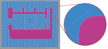
Look closely around different areas of the grass object. You will probably notice that 3ds Max did not do a very good job of cutting the extruded object out of the grass object. There are probably numerous missing and deformed faces along the edge of where the cut took place, as shown in the next illustration. There is a very good reason for this. Boolean operations do not work well when some of the faces that have to be created are long and skinny, as is the case in this scene. The reason the faces are long and skinny is because of the distance and angle between vertices of the road object and vertices of the cutting object. If an operation does not work right the first time, simply increase the polygon density of the object being cut using a modifier such as Subdivide.

83. From the Edit menu, select Fetch and Yes to complete the command. This returns the scene to the pre-Boolean configuration.
84. With the Site-Roads object selected, add the Subdivide modifier and change the Size value to 10’. Making the maximum face size 10’ will make the cuts much more accurate.
85. Select Create > Geometry > Compound Objects > Boolean > Cut > Split.
86. Add the Edit Poly modifier and enter Polygon sub-object mode. The cut polygons are automatically selected.
87. Press the keyboard shortcut Ctrl+I to invert the selection of polygons.
88. Within the Edit Geometry rollout, click the Settings icon immediately to the right of the Detach button.
89. Name the object Site-Grass_Inside and click OK to complete the Detach command.
90. Close out of sub-object mode, select the new object you just created/detached and give the object a new color. This allows it to be distinguished from the polygons that were just detached.
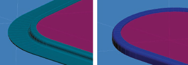
91. Analyze the cut that was just made. This time you should have clean edges all around your road object, as shown in the next illustration, because 3ds Max doesn’t have to create long, skinny faces.
As mentioned earlier, the road object will remain at the home grid; however, the grass object needs to be elevated above it as it would be in the real world. Normally grass is found growing above a curb, sidewalk, and any other similar site element. But because we want the option to apply displacement to the grass to make it rise above these elements, we will leave it positioned 1 inch below the top of the curbs. Also, since the grass is nothing more than a surface, and since we don’t want to have to generate any unnecessary polygons, elevating the grass object above the curb means that there will be a gap between the curbs and the grass. This is obviously unacceptable and for both of these reasons, the grass should be raised so that it’s just below the top of the 6-inch tall curbs we created earlier.
92. Exit isolation mode and select objects Site-Grass_Inside and Site-Grass_Outside.
93. Switch to Orthographic view, zoom in closely to one of the curb areas, and move both objects upward 5 inches so they are positioned just 1 inch below the top of the curb objects. The following illustration shows what the curbs should look like in a couple of different places.
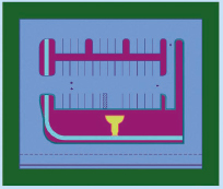
Now might be a good time to change the background color of your scene to something lighter. Black backgrounds can negatively impact the mood of your renderings and it’s best to use a lighter color, even for test renders.
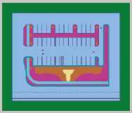
94. Change the background color of your scene to a light blue color, similar to a midday sky color.
95. Render the scene. It should look similar to the following illustration.
96. Save the file.
Sidewalks
Now that we have our roads and curbs created, let’s create perhaps the easiest object in the site; the sidewalks.
97. Continue from the previous exercise or open the file ch07-04.max.
98. Select the object 0-Site-Sidewalks.01.
99. Add the Extrude modifier and use an Amount value of 6 inches. This makes the top of the sidewalks flush with the top of the curbs, as shown in the following illustration. By extruding the sidewalks 1 inch higher than the surrounding grass, you can add displacement to select areas and make the grass appear to grow over the sidewalks as it would in the real world.

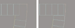
The only other structural modification that should be made to this object is applying joint lines, as you would typically find in the real world. In the real world, these joints would be about 1/4 of an inch wide and deep. However, joints with these dimensions simply will not show up well unless viewed from a very short distance. Because of this, you should always beef up the size of the joints. To create the joints, all we need to do is subtract a volume from the sidewalks as we did when creating window openings in the chapters dealing with walls. To make this exercise flow quickly, an object has already been prepared and is ready to be cut out of the sidewalks.
100. Merge into your current scene the sole object in the file sidewalk-booleans.max. The merged object should be a series of boxes, as shown in the left image of the following illustration. The distance between joint lines in the real world is typically 4 to 6 feet, so in this case, a distance of 5 feet was used. As an additional note, the boxes are 1 inch wide and have been placed 1 inch into the sidewalk object.
101. Select the object 0-Site-Sidewalks.01 and select Create > Geometry > Compound Objects > ProBoolean.
102. Click the Start Picking button and then click the object sidewalk-booleans in the viewport. The result should look like the right image in the following illustration. The ProBoolean feature was used here to keep the geometry clean looking and to prevent extra coplanar edges from being displayed automatically, as they would have been with the Boolean feature.

103. Rename the object Site-Sidewalks.
104. Save the file.
Pavers and Paver Bandings
The next two object types we need to create for this scene are pavers and the bandings that surround them. Both are usually just bricks arranged in a specific pattern to form a beautiful type of site element often referred to as hardscaping. When created correctly, they can add a wonderful touch of realism to a scene.
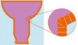
Paver bandings provide a great accent to the pavers in any project and 3D artists often make the mistake of not taking the extra step of adding this key element to their work or not orienting the bandings correctly. Whether around a pool, on a sidewalk, or in a street, bandings make a big difference in the look of a hardscape area; when placed improperly, they can stand out like a sore thumb. The images in Figure 7-12 show several different examples of paver bandings oriented in a specific manner around other paver bricks. Imagine how these images would look if the paver bandings didn’t exist or if they were all oriented in an inappropriate manner, for example if all the pavers were aligned in the same direction when they should instead be oriented in a radial fashion.
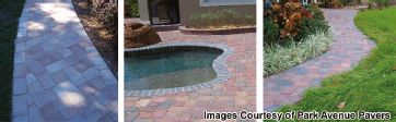
Figure 7-12. Examples of pavers and paver bandings.
In this project, the paver bandings used were nothing more than applications of poured concrete, rather than individually placed bricks. This made creating the bandings for this project very quick and easy. However, for the sake of proper coverage of the subject, I will provide a few tips on how to efficiently create the look of bandings arranged in a specific way around the rest of the pavers.
105. Continue from the previous exercise or open the file ch07-05.max.
106. Switch to a Top view.
107. Select and isolate the two objects, 0-Site-Pavers_Banding1.01 and 0-Site-Pavers_Banding2.01.
108. Make a clone of the object 0-Site-Pavers_Banding2.01 and rename it Site-Pavers.
109. Extrude this object 6 inches. The result should look like the left image of the following illustration.
110. Select the object 0-Site-Pavers_Banding1.01 and attach the object 0-Site-Pavers_Banding2.01.
111. Extrude this object 6.5 inches. The result should look like the right image of the following illustration. Making this object slightly higher than the pavers it surrounds provides a nice distinction between the two objects.
112. Rename this object Site-Paver_Bandings.
113. Exit isolation mode.
114. Save the file.
As mentioned, the bandings for this project are solid concrete poured in place, and therefore, very simple to create in 3D. More often than not, however, bandings require precise orientation around an often complex perimeter, such as an oddly shaped pool. When this is the case, you have two choices to represent the pavers; with a texture or with actual 3D objects representing each individual brick. Because the number of pavers needed for a banding feature is usually relatively small, I would recommend placing 3D pavers rather than a texture. Placing these bricks can be time consuming, but there is a useful tool that can make it much quicker and far more precise than manual placement. If you find that a texture is the most reasonable solution, you will probably have to work equally hard to make the pattern look proper. Whichever your choice, the following exercises demonstrate 2 methods you might want to use to make the job a little easier.
3D Paver Bandings
115. Open the file paver_exercise01.max. This file contains 4 objects. One object is a 6x12 inch paver with a thickness of 6.5 inches, which is just thick enough to rise through another object that represents the grout that will be seen through the pavers. A third object is the large interior area inside the banding where the pavers can be mapped, and the fourth object is a spline that will be used as a path for the tool of choice for this exercise; the Spacing Tool.
116. Select and isolate objects 3D-Paver01 and Site-Pavers_Guide.
117. Deselect both objects and select only the 3D-Paver01 object.
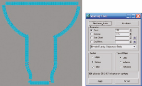
118. Press the keyboard shortcut Shift+I to activate the Spacing Tool. This tool can also be found in the Array flyout of the Extras toolbar in 3ds Max 2009. In previous releases, this tool is found in the Tools menu.
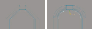
119. In the Count field type 150, in the Context section enable the Follow option, and in the Type of Object section enable the Copy option, as shown in the right image of the following illustration.
120. Click the Pick Path button, click on the Site-Pavers_Guide object in the viewport, click the Apply button and close the dialog box. There should now be 150 copies of the 3D pavers positioned as evenly as possible around the path. As good as this tool is, it can’t do miracles and make the spacing between the pavers perfect around sharp corners, so some manipulation will be necessary with the Edit Poly modifier.
121. Delete the original 3D paver off to the side.
122. Exit isolation mode.
123. Select one of the 3D pavers you created, and attach all the other pavers to it.
124. Enter Element sub-object mode and make copies of the pavers as necessary to fill in the areas where pavers should exist. You will also need to delete a few pavers and reposition others and you will also need to enter Vertex sub-object mode and manipulate individual vertices as necessary to produce a proper arrangement. This should take a few minutes, and the following illustration shows a before and after view of one area in Wireframe.
125. Render Top view. The result should look similar to the following illustration. If you want to see a completed version of this exercise, open the file paver_exercise01-completed.max.

Textured Paver Bandings
If you decide that 3D paver bandings will place too much of a strain on your computer’s resources and you want to instead use a texture that simulates the look of what you created in the last exercise, you have a few choices. The first is to loft a shape along the same path used in the last exercise and enable the mapping option unique to lofts. The benefit of this method is that it is a great way to quickly create mapping that follows the path of the banding. This is the method we will use in the following exercise. Another way is to use the new Spline mapping feature found in the Map Parameters rollout of the Unwrap UVW modifier. Yet another way you can create the proper texture is by creating 3D pavers as described in the last exercise, and then rendering a high resolution image to be used as the texture. This is a nice technique, but will of course require you to do all the work of placing the 3D pavers in their proper location and orientation first.
126. Open the file paver_exercise02.max. This file contains 3 objects. One object is a 6x12 rectangle that will serve as the loft profile. A second object is the interior object that represents the area where the inside pavers can be mapped, and a third object is the same path used in the last exercise with vertices manually inserted, and with vertex ticks enabled so you can clearly see where the path contains vertices.
127. Create a loft using the object Site-Pavers_path as the path and the object Paver-shape as the shape.
128. Open the Material Editor and apply the lone material you see in the 1st sample slot.
129. Within the Skin Parameters rollout of the Modify panel, reduce the Shape Steps and Path Steps to 0, if not already set from a previous use.
130. Within the Surface Parameters rollout, enable Apply Mapping (if not already enabled) and type a Length Repeat value of 150. This forces 3ds Max to use the path as a mapping guide so the orientation of the bitmap follows the path. The 150 value specifies how many times the bitmap will be repeated throughout the length of the path, as shown in the next illustration. Incidentally, if you didn’t set Real-World Map Size to be disabled by default in 3ds Max 2009 you will have to disable it now in order for this step to work correctly.
Unfortunately for this scene, the paver bandings can’t be simulated very well using this method because of the sharp corners in the path. Because of the sharp corners, the bitmap gets stretched, bent, and generally distorted, rather than tiling seamlessly as it does along the gradual bends in the path. Nonetheless, this technique is invaluable for many paver bandings because this particular problem is not typical with most projects. Applying this technique to a rounded pool for example will result in perfectly seamless mapping and can be done in seconds.
Road lines
Road lines are a simple yet critical element of many 3D sites. If our road was 3D with varying elevation, the process we would use to create this object type would be similar to the way many of the site elements are created; with the Boolean > Cut > Split feature. Since our road is completely flat, however, the process is much easier and can be completed in much less time. The AutoCAD drawings we started with displayed the road lines as simple polylines with a width of 6 inches (the standard thickness for most road lines). When imported into 3ds Max, plines become perfect splines to work with and need only to be turned into mesh or poly objects to be renderable.
131. Continue from the previous exercise or open the file ch07-06.max.
132. Select and isolate the object 0-Site-RoadLines.01 and apply the Edit Poly modifier.
133. Render Top view. Since the lines are imported as closed splines, they can be made to render just by being converted into an editable mesh or poly object. However, notice that the center road line did not import properly. Instead of importing as a dashed line as shown in the site drawing, it was imported as a single closed spline. This is because the DWG file type does not allow linetype patterns to be translated into a similar looking spline as shown in the AutoCAD drawing. There is a way to make this translation happen, but it requires you to do something different inside AutoCAD. If you do not have AutoCAD, you simply can’t take advantage of this technique.
134. Return to the AutoCAD file metro_cleaned.dwg.
135. Select and isolate the 0-Site-RoadLines layer.
136. Type the command 3dsout. You are asked to select the lines you want to export using this command. Sadly, the 3DSOUT feature was removed from a recent release of AutoCAD, which is why I recommend using an older version of AutoCAD that still has this feature, such as 2004. Nevertheless, you can download this feature from the Autodesk support website.
137. Select all of the green road lines and press Enter twice to complete the selection.
138. Enter a file name and save the file to your computer.
139. Return to your 3ds Max scene and delete the object with all of the road lines.
140. Import the 3ds file you just saved using the default options. If you don’t have AutoCAD, you can import the file road_lines.3ds. Notice that the dashed lines are now translated properly.
141. Add the Edit Poly modifier to the road lines.
It is important to note that AutoCAD uses whatever linetype scale you have specified to determine the scale of the exported plines. This simply means that whatever you see in AutoCAD is what you get imported into 3ds Max.
142. Exit isolation mode.
143. Move the road lines up .25 inches in the Z direction. This will elevate the lines just enough above the road.
144. Right-click inside the active viewport, select Object Properties and disable the Cast Shadow option. This ensures that the lines will not cast shadows and appear to be anything more than paint on the roads.
145. Rename the object Site-RoadLines and change the color of the object to something that stands out better against the road object.
146. Render Top view. The result should look like the next illustration.
147. Save the file.
Mulch
One of the most important components of a good landscape plan is the layout of mulch. I use this term generally to describe any type of substance immediately surrounding vegetation—wood chips, gravel, rock, etc. Mulch is usually a very simple object to create and can be created very quickly even for very large developments. If you are fortunate enough to have CAD drawings from which to pull mulch linework, then your work may be simplified as long as the linework is well-created. If the linework is problematic, it might be better to just import it into 3ds Max as is, quickly trace a similar outline and then delete the original linework. If landscape plans are non-existent, you may find yourself having to come up with what you hope your client finds to be good enough. Fortunately, for this project a landscape drawing was available for this project and the layout of the mulch was placed within the site drawing.
148. Continue from the previous exercise or open the file ch07-07.max.
149. Select the object 0-Site-Mulch.01 and extrude it 20’.
150. Move the object down 10’ in the Z direction to make it intersect the Site-Grass_Inside object.
151. Select the Site-Grass_Inside object and apply the Subdivide modifier with a maximum face size of 5’. This will help guarantee that the Boolean operation that will be performed next operates smoothly.
152. Use the Boolean > Cut > Split feature to cut the mulch area out of the surrounding grass object.
153. Add the Edit Poly modifier, enter Polygon sub-object mode and detach the mulch area using the name Site-Mulch.
154. Close sub-object mode, select the Site-Mulch object and give it a new color so it stands out from the surrounding grass object. The result should look like the following illustration.
Notice that as a result of the multiple times the subdivide command was used to prepare for Boolean operations, there are numerous interior edges on the road, grass, and mulch objects. You can always leave these edges in your scene, but at times they can become a distraction and make it harder to see other objects. If this is the case, and you want to remove them, you can take advantage of the power of the ProBoolean command.
155. Select and isolate the Site-Mulch object.
156. Create a plane inside the mulch object without allowing the plane to touch any portion of the mulch, as shown in the left image of the following illustration. The number of length and width segments is not important.
157. Select the Site-Mulch object and apply the ProBoolean feature.
158. Click the Start Picking button and click on the plane you just created. The result is that all of the interior coplanar edges are removed on the mulch object, as shown in the right image of the following illustration. The Advanced Options rollout of the ProBoolean feature contains the option that allows for the removal of all coplanar edges as well as the ability to turn the 3-sided faces into 4-sided polygons. Applying the ProBoolean feature to the small plane we created simply allowed us to take advantage of the ProBoolean’s power without having to subtract or cut any part of the mulch object.
159. Exit isolation mode.
160. Repeat this edge removal process on the Site-Roads and Site-Grass_Inside object.
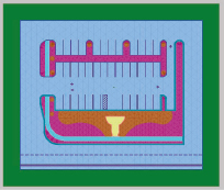
161. Render Top view. The result should look similar to the following illustration.
162. Save your file.
Parking Stops
When its linework is set up properly, the parking stops object can be one of the quickest and easiest site objects to create in 3ds Max. If you refer to the original site drawing, you will notice that there are multiple lines depicting the parking stops in plan view, as shown in the left image of Figure 7-13. The parking stop is 8 inches wide and consists of 2 chamfered corners, as shown in the right image. The easiest way to create this particular object is to replace the multiple lines in the original site drawing with one individual line for each parking stop (center image) and use the Sweep modifier with a proper shape (right image).
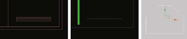
Figure 7-13. The original linework for the parking stops (left) and the new linework (center and right).
163. Continue from the previous exercise or open the file ch07-08.max.
164. Next to the other 2 shapes located at the origin of the scene, create a rectangle with a length of 6 inches and a width of 8 inches.
165. Add the Edit Spline modifier, enter Vertex sub-object mode and apply a 2 inch chamfer to the top left and top right vertices, as shown in the right image of Figure 7-13. Since we are going to use the Sweep modifier with this shape, we don’t need to adjust the pivot point of the shape.
166. Select the 0-Site-ParkingStops.01 object and apply the Sweep modifier using the new shape you just created as the custom section type.
167. Change the alignment of the sweep object to the bottom-center so the bottom of the parking stop object is resting directly on the road object, as shown in the following illustration.

168. Change the name of the object to Site-ParkingStops.
169. Save the file.
This completes this 2D site exercise. The final geometry should look similar to the following illustration. If you want to see the completed scene, open the file ch07-09.max.

Summary
If you’ve ever spent much time pursuing the numerous chat forums we have available in our industry, you’ve noticed that sites are a source of great frustration for so many users. The reasons are numerous, such as the sheer size of some sites, lack of understanding civil engineering data, the inability to manage high poly objects such as trees and cars, and so on. But in reality, the best thing anyone could do to improve his or her workflow for site creation is to better clean and prepare the original linework before it’s ever brought into 3ds Max. It should be clear from this exercise that sites can, and probably should, be created with just a few key features. It should also be clear that once linework is prepared properly, you can create a decent site in a relatively small amount of time. By practicing these same techniques over and over again, a site of this magnitude could take well under an hour to create.