
CHAPTER 6
Creating Furniture

Introduction
People ask us from time to time, ‘What do you look for in a 3D user?’ Our usual answer is, ‘Someone who can produce realistic exteriors.’ We say this because it appears to us that far more users struggle with the realism of exterior scenes than interior scenes. While new users are often able to produce beautiful interior visualizations, their exteriors often lack the same believability and realism. There are numerous reasons for this, including a lack of understanding of site plans, not knowing how to create proper landscaping (especially in the absence of a landscaping plan), the usually larger scene size unforgiving of inefficient workflow, and so on. And although it’s apparent to us that exterior scenes are far more difficult for users to make believable, it also seems clear that interior scenes have their own unique problems that make them more agonizing to work on.
What makes interior scenes so painful for so many users is the difficulty in helping the client make good furniture and material selections. Unlike modeling from architectural drawings, interior design is more of an art than a science. If a hundred 3D users from all corners of the world receive the same set of architectural drawings, they should all produce nearly identical models, assuming of course the drawings are complete and well-built. But the moment you start working on furniture and material selections, everyone and his or her brother has something to say about the selections made. The drapes are too yellow, the couch is too contemporary, the table is too shiny, the flooring is too boring, and the list goes on. With most interior jobs we’ve worked on, the clients don’t have a decent interior design planned out and often have no idea what they want. When they see your attempt at interior design they can be quick to tell you that they don’t like your selections, but getting them to make sound decisions of their own can be a monumental undertaking. Having pained our way through the process of creating interior scenes for so long, we learned long ago to adapt our workflow to accommodate the most difficult clients.
When you present your proposal for interiors to a client, you need to decide whether your client needs or wants custom furniture or if stock furniture is the better choice. If you try to present your client with stock furniture, you of course have to have a large enough selection of high quality furniture and materials from which the client can pick. Unfortunately, many clients don’t want to spend the time sifting through hundreds or even thousands of different images of furniture and material selections to find something suitable for their project. Even if they are willing to give it a try, many cannot see past the default colors or materials on the stock furniture and envision different materials or colors on a piece of furniture that might otherwise make a suitable choice. And even if you have an enormous library of furniture and materials, if you don’t present those libraries in an easy to navigate manner, the client might quickly give up in frustration. Because of all the potential difficulties in working with clients on these selections, you should always budget for the unexpected.
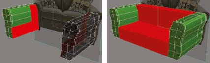
Figure 6-1 shows one example of a project where the client changed the furniture and materials over and over again, first trying to use stock selections, but in the end relying entirely on custom furniture and materials. Fortunately for us, we always anticipate this possibility on all projects and cover ourselves in our proposals by making it clear to the client from the start the types of changes that incur added cost. This particular client ended up paying more for changes to furniture than what was originally allotted for in the entire project. The bottom line is that you have to know your clients and determine if they are willing to endure the work of choosing custom furniture and materials. If not, you should do everything you can to sell them on custom furniture without scaring them away with too much added cost. If custom furniture is the chosen course, then the only other thing to decide is how to go about creating the furniture. If you would like to see an example of how we work with our clients to create custom furniture, refer to the tip in Appendix A that discusses the selection of furniture. In it we show what we actually send to our client when the determination is made to create custom furniture.
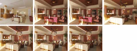
Figure 6-1. An example of the transformation interior projects often undergo.
Furniture creation is a very specialized skill and while many of us can create furniture, creating it fast and detailed is a completely different issue. Unless furniture creation is a specialty skill you possess, you would probably be doing yourself a favor to contract custom furniture creation to someone who specializes in it. Otherwise, you might spend several times longer creating furniture that is of far less quality. If you have a need to contract out this important part of your interior scene, we recommend the author of this chapter, Alexander Gorbunov from Intero Visuals (www.interovisuals.com). His skill in furniture creation is truly amazing and we are delighted to have him write a chapter for us on the creation of furniture.
Creating a Sofa
One of the most difficult challenges of a 3D interior project is providing the client with suitable 3D furniture. Many times the client does not want to use stock furniture or take the time to look through so many sample images. When this is the case, creating custom furniture is the only alternative. But if not done wisely, creating custom furniture can be a very time-consuming process and can end up taking longer than the entire rest of the project.
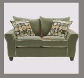
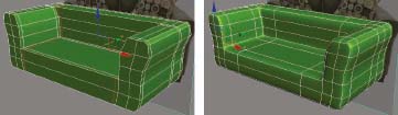
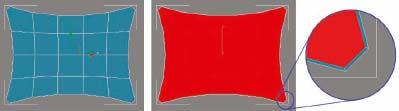
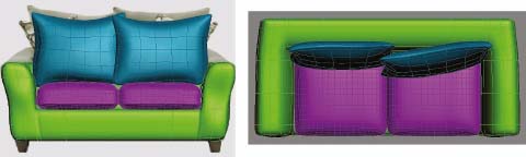
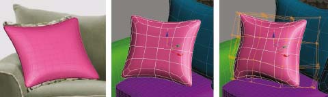
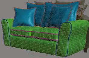
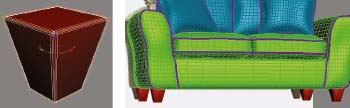
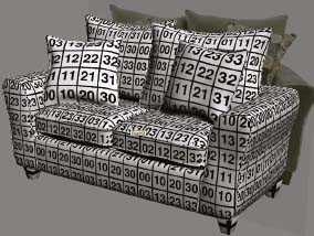
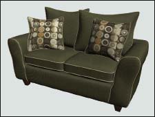
The following is a pictorial-based tutorial that demonstrates how to quickly and efficiently create the sofa shown in Figure 6-2 starting with nothing more than a simple image. The image on the left is a photograph of the real sofa and the image on the right is the sofa this chapter explains how to create. Using the tools and methods highlighted here, you can create almost any type of furniture you want.

Figure 6-2. The sofa to be modeled in the following exercise.
Creating a Sofa
In this exercise, we need to start by analyzing the left image of Figure 6-2, which will be our only reference in creating the sofa. Try to picture in your mind the parts of the sofa that are not visible from this vantage point and then build a plan of how to model this object. For example, we cannot see the back of the sofa, but it is easy to picture what this part would look like. Most likely, it’s just a bridge that connects the left and right armrests, although we can certainly use artistic liberty to modify as we see fit.
Think about what parts should be modeled first and what techniques should be used. Think about what parts should be modeled precisely as shown in the reference image and what parts can be simplified.
So let’s come up with the plan of how we would model this sofa part by part. A logical progression might look something like this:
1. Prepare the 3ds Max environment
2. Modeling the armrests
3. Modeling the bottom and back
4. Modeling the seat cushions
5. Modeling the back pillows
6. Modeling the throw pillows
7. Modeling the decorative trim piping
9. Texturing
10. Assigning materials.
Now that we know the order in which we will build our sofa, we can begin the creation process.
1. Preparing the work environment
In this step, we are going to bring the reference image into the 3ds Max environment so we can use it as a visual reference anytime we need it, and then we are going to model the two armrests of the sofa.
1. Reset 3ds Max.
2. Set your units to U.S. Standard and Fractional Inches and precision to the default 1/8. Having chosen this particular unit of measure, it is extremely important to note at this point that care must be taken when typing in fractional units inside 3ds Max. On architectural drawings, 1.5 inches would be written as 1-1/2”. However in 3ds Max, you must replace the dash with a space. Therefore, 1.5 inches would be written as 1 1/2”, with a space after the first number.
3. Disable the Show Grid option in all 4 viewports.
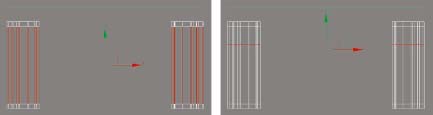
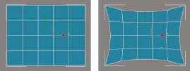
4. In Front view, create a simple plane with a width and length of 70 inches and with 1 length and width segment.
5. Switch to Perspective view and move the plane 36 inches in the positive Y direction, which is away from your current view. The plane needs to be pushed back in the scene so it doesn’t block the view of new objects created at the home grid, as seen from Front view.
6. Enable Edged Faces mode in Perspective view.
7. Activate Front view and switch from a 4-viewport configuration to a single viewport configuration.
8. Enable Smooth+Highlights as well as Edged Faces mode.
9. Disable selection brackets in each viewport (shortcut = J). This makes working in segment sub-object mode a little easier because it doesn’t obstruct the view of selected edges.
10. Zoom to the extents of the Front view.
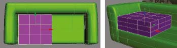
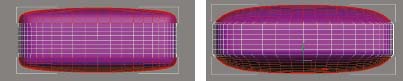
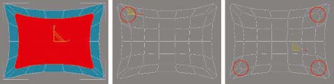
11. Using the Material Editor, apply the image couch.jpg to the plane you just created. The plane should look like the next image. If you are using 3ds Max Design 2009, you will have to disable the Real-World Map Size option within the Command panel and the Use Real-World Scale option within the Coordinates rollout of the bitmap applied. Both of these are enabled by default and prevent the mapped image from displaying properly without mapping adjustments.
12. Save the scene.
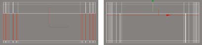
2. Modeling the armrests
In this step, we are going to model the two armrests using the Edit Poly method known as box modeling. This will be the initial element of the sofa model and will help us establish the proportions of all other objects we create. Also, since the couch is symmetrical, we do not need to model both armrests. After creating one, we will simply create a mirrored copy of the other.
13. Continue from the previous step or open the file ch06-01.max.
14. In Front view, create a plane that covers the entire front surface of the right armrest, as shown in the left image of the next illustration.
15. In the Modify panel, set the length segments to 5 and the width segments to 1.
16. Press the shortcut Alt+X to make the plane object transparent. Note that if you are using 3ds Max 2009 with the default configuration, you will have to first change the object’s display properties so they aren’t set to the By Layer option.
17. Add the Edit Poly modifier to the plane.
18. Go to Vertex sub-object mode and move each individual vertex along the X-axis to make the shape of your object roughly match the shape of the front surface of the armrest, as shown in the right image of the next illustration.
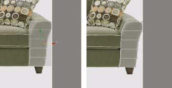
19. Press the shortcut Alt+X again to make the object no longer transparent.
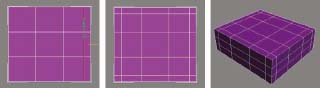
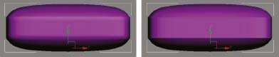
20. Go to Perspective view, apply the Shell modifier, and set the Inner Amount to 31” and Outer Amount to 0”. The result should look similar to the next image.
21. Add the Edit Poly modifier.
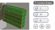
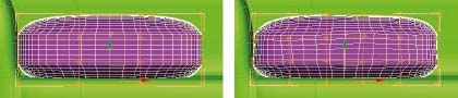
22. Go to Edge sub-object mode, select any edge that is parallel to the Y axis, as shown in the left image of the next illustration, and click the Ring button in the Selection rollout. This causes the selection to grow around the first edge selected.
23. In the Edit Edges rollout, click the Settings icon immediately to the right of the Connect button. This opens the Connect Edges dialog box.
24. Enter a Segments value of 2 and a Pinch value of 87. Click OK to complete the command.
25. Select any edge that is parallel to the X axis and click the Ring button.
26. Click the Settings icon immediately to the right of the Connect button and enter a Segments value of 1 and a Pinch value of 0. Click OK to complete the command.
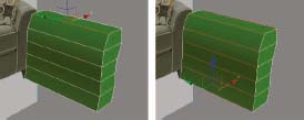
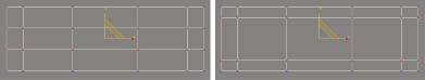
27. Rotate the Perspective view to see the object from the right-hand side, as shown in the next illustration.
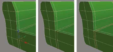
28. Select the two edges shown in the left image of the next illustration. These are the middle edges at the top-right and bottom-right corners of the object.
29. Click the Loop button to extend the selection of edges to the ends of the object.
30. Click the Settings icon to the right of the Chamfer button. This opens the Chamfer Edges dialog box.
31. Enter a Chamfer Amount of 1” and click OK to complete the command.
32. Close Edge sub-object mode.
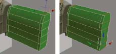
33. Switch to Front view and add the Mirror modifier.
34. Enable the Copy option and use the Offset feature to align the left armrest, as shown on the left side of the next illustration.
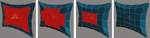
35. Switch to Perspective view, apply MeshSmooth modifier to the object and set the Iterations value to 2. We do not need to keep the armrest in this smoothed configuration right now. We applied this modifier just to take a quick look at the model in smoothed mode, as shown on the right side of the next illustration. Once we are sure that everything is OK with the model, we can remove the modifier.

36. Remove the MeshSmooth modifier.
37. Save the scene.
38. We just modeled the initial elements of our sofa. All other objects we model will be created while using the armrests as a reference. The armrests are properly scaled and placed at right distance from each other and this helps us understand proportions of the remaining elements.
3. Modeling the bottom and back
In this step we are going to model the bottom and the back of the sofa, which will connect the left and right armrests. You might notice that because some of the features have been repeated so many times before, a description of how they are executed will become more and more abbreviated as the exercise continues.
39. Continue from the previous step or open the file ch06-02.max.
40. With the object selected, switch to Top view, add another Edit Poly modifier, and enter Edge sub-object mode.
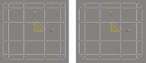
41. Using the left image of the next illustration as a guide, select the middle edges that run parallel to the Y axis and connect the front and rear parts of the armrests.
42. Click the Settings icon to the right of the Connect button and use a Segments value of 1. Click OK to complete the command. This will insert an extra loop of edges within the selection.
43. Move the newly created edges toward the back end of the armrests, which in Top view would be upward. Place the edges approximately one-quarter away from the back end of the armrest, as shown in the right image of the next illustration.
44. Switch to Perspective view, enter Polygon sub-object mode and carefully select the inner polygons on both armrests as shown in the left image of the next illustration. You will need to navigate around in Perspective mode to select the polygons properly.
45. In the Edit Polygons rollout, click the Bridge button. This creates a connection bridge between the selected polygons that represents the bottom and back parts of the sofa, as shown in the right image. If your bridged polygons appear twisted, rather than the way shown in the following image, undo the Bridge command, click on the Settings icon next to Bridge, and use the Twist settings to remove the twist applied.
46. Switch to Top view, enter Edge sub-object mode and select all middle edges that run parallel to the X axis and connect the front and rear parts of the armrests, as shown in the left image of the next illustration.
47. In the Edit Edges rollout, click the Connect button to add 1 set of edges running around the middle of the selected edges.
48. Move the newly created edges toward the back of the sofa, as shown in the right image of the next illustration.
49. Switch to Perspective view and select any edge that connects the left and right armrests, such as the one selected in the left image of the next illustration, and click the Ring button. All the edges that connect the right and left halves of the couch are selected.

50. Click the Settings icon to the right of the Connect button and enter a Segments value of 2 and a Pinch value of 94. Click OK to complete the command. The pinch value pushes the selected edges 94% away from their initial location. This places these new edges relatively close to the armrests. This allows the curvature applied with the MeshSmooth modifier to be confined closer to the armrests rather than extending far out into the middle of the couch.
51. Temporarily apply the MeshSmooth modifier with an Iterations value of 2 to check the appearance of your model. If your model looks similar to the one shown in the following illustration you are on the right track.
52. Remove the MeshSmooth modifier.
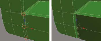
53. While still in Perspective view, zoom in to the left side of the model.
54. Enter Edge sub-object mode and select the edge shown in the left image of the next illustration.
55. Click the Ring button to grow the selection completely around the sofa, as shown in the middle image of the next illustration.
56. Click the Settings icon to the right of the Connect button.
57. Enter a Segments value of 1 and a Pinch value of 0. Click OK to complete the command. One additional set of edges is created around the sofa, as shown in the right image of the next illustration.
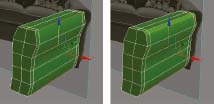
58. Switch to Vertex sub-object mode and select the 3 vertices shown in the left image of the following illustration.
59. Move the selected vertices 3/8” in the positive Y direction (inward to the sofa), as shown in the right image.
60. Repeat the previous 6 steps to add and move these same vertices on the right side of the sofa. You can add the MeshSmooth modifier again at this point if you want to check the effect of pushing these 6 vertices inward toward the center of the couch.
In the real world, the back of a sofa will undoubtedly be narrower than the front, and now would be a good time to make this modification.
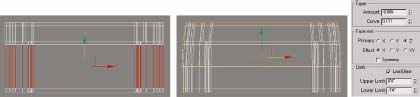
61. Switch to Top view and select all of the middle edges that run parallel to the Y axis and connect the front and back parts of the object, as shown in the left image of the following illustration.
62. Using the Connect feature, create 1 new set of edges around the sofa. These new edges are necessary to help control the effect of the next modifier that will be added.
63. Go to the Hierarchy panel, click the Affect Pivot Only button, and then click the Center to Object button. We cannot apply the next modifier properly without first centering the pivot point on the object like this.
64. Apply the Taper modifier to the object using the following settings: Amount = 0.086, Curve = 0.111, Primary = Z, Effect = X, Limit effect = Enabled, Upper limit = 4”, Lower limit = -16″. The result should look like the right image in the following illustration.
To properly finish the parts of the sofa we’ve created thus far, we need to do some fine tweaking. Toward the end of the exercise, we are going to apply the MeshSmooth modifier to the sofa, but the results will look much better if we first make the sofa look less uniform and more erratic. By building more bulges into the structure of the sofa, the MeshSmooth modifier can make the final sofa appear much smoother and less chiseled.
65. Switch to Perspective view and add another Edit Poly modifier.
66. Enter Vertex sub-object mode and use all three transforms to symmetrically modify the vertices so the sofa takes on a more natural shape and doesn’t look too perfect. The top left image of the following illustration shows the sofa before modifying the vertices and the top right image shows the result after.
67. Temporarily apply the MeshSmooth modifier to see the result of modifying the vertices.
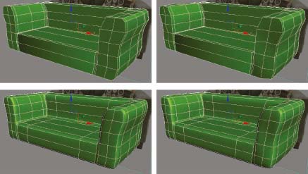
68. Remove the MeshSmooth modifier.
69. Save the scene.
4. Modeling the seat cushions
In this step, we are going to model one seat cushion and copy it to create another. We will then apply tools to make the two copies appear unique.
70. Continue from the previous step or open the file ch06-03.max.
71. Go to Top view and enable Smooth+Highlights and Edged Faces mode.
72. Create a box object with a Length and Width of 22”, a Height of 8”, and 3 length, width, and height segments.
73. Position the box so it rests approximately where a cushion would rest on a sofa in the real world. If the size of your cushion needs to be adjusted a few inches so it better fits the sofa, do so at this time. You should see something similar to the next illustration.
74. Isolate the box so you can work on it without being distracted by the other geometry.
75. Add the Edit Poly modifier.
76. Enter Edge sub-object mode and select the edges as shown in the next illustration. All horizontal edges on the right third of the box should be selected.

77. Use the Connect feature with a Segments value of 1 and a Slide value of 50. The Slide value causes the newly created edges to move 50% toward one end of the edges that had previously been selected, as shown in the left image of the next illustration.
78. Repeat the previous step with the other 3 sides of the cushion. You will have to use a -50 value on the left and bottom sides of the box. The result should look like the middle and right images in the following illustration.
79. Switch to Front view, enable Wireframe view, and zoom to the extents of the cushion.
80. Enter Vertex sub-object mode and create a window selection around the vertices shown in the left image of the following illustration. Since Ignore Backfacing is disabled, all of the vertices behind those shown should be selected.
81. Use the Non-Uniform Scale feature to scale the selected vertices 200% along the Y axis only, as shown in the right image. This pushes the selected vertices away from each other and closer to the top and bottom of the cushion so that when curvature is applied to the cushion, the effect is confined more to its perimeter.
82. Switch to Top view, select all corner vertices and use the Non-Uniform Scale feature to scale the selected vertices 5% inward (along the X and Y axis only) to the center of the cushion. An easy way to do this is to open the Scale Transform Type-In dialog box and enter an X and Y value of 95. The result should look similar to the right image of the following illustration. The illustration is shown in Wireframe mode for ease of display.
83. Switch to Perspective view and zoom to the extents of the cushion.
84. Enter Polygon sub-object mode and select the polygons shown in the left image of the following illustration.
85. Move the selected polygons 1/4” upward along Z axis.
86. Select the polygons shown in the middle image and move them upward another 1/4”.
87. Select the center polygon shown in the right image and move it upward another 1/2”.
88. Repeat the previous 4 steps to the bottom of the cushion to make the cushion appear symmetrically inflated.
89. Exit Polygon sub-object mode and apply the MeshSmooth modifier with an Iterations value of 2.
90. Switch to Front view, add another Edit Poly modifier to the cushion, and enter Polygon sub-object mode.
91. Select the polygons shown in the left image of the following illustration.
92. Apply the Relax modifier with a Relax Value of 0.5 and an Iterations value of 48. The selected polygons should look like those shown in the right image.
93. While still in Front view, disable Edged Faces mode.
94. Add another Edit Poly modifier.
95. Apply the Smooth modifier and enable the Auto Smooth option. The result should look similar to the right image of the following illustration. Giving the cushion a stronger edge like this is necessary because we need to apply a decorative trim to the cushion and doing so with a smoothed edge would look strange.
96. Exit isolation mode.
97. While still in Front view, re-enable Edged Faces mode.
98. Adjust the position of the cushion object so it appears to be in the correct position on the sofa.
99. Apply the FFD (box) modifier. Click on the Set Number of Points button and enter a Length and Width value of 6 and a Height value of 4.
100. Open the FFD modifier and click on the Control Points category inside the modifier stack.
101. Move individual control points to deform the cushion so it looks more natural and less rigid. Refer to the before and after images in the following illustration and close the FFD modifier when you’re finished. A before and after version might look like the following illustration. Subtle variations in the pillow’s ‘perfect’ structure can do a lot to make the pillow look more natural.
102. Make a copy of the left cushion and place it in the right cushion position.
103. Slightly modify the control points of the 2nd cushion to make the two cushions appear unique. Close the modifier when you are finished.
104. Save your scene.
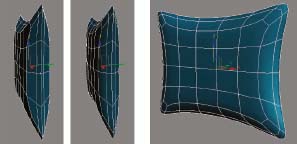
5. Modeling the back pillows
In this step, we are going to model one of the back pillows and then copy it to create the other.
105. Continue from the previous step or open the file ch06-04.max.
106. Hide all objects in the scene.
107. Go to Front view and create a plane with a length of 20”, a width of 28”, 4 length segments and 5 width segments, as shown in the left image of the following illustration.
108. Add the Edit Poly modifier to the object.
109. Go to Vertex sub-object mode and use the Move and Scale transforms to position vertices similar to those shown in the right image. This shape will serve as the basis for the outer profile of the back pillows.
110. Select the 4 corner vertexes.
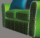
111. Click the Settings icon to the right of the Chamfer button and apply a Chamfer Amount of 1 1/4”. The result should look similar to the left image, of the next illustration.
112. Switch to Polygon sub-object mode and select all of the polygons in the object.
113. Click the Settings icon to the right of the Inset button and apply a Group inset value of 1/8”. An additional line of vertices is created 1/8th of an inch away from the outer perimeter of the object, as shown in the middle and right images of the next illustration.
114. Apply a non-uniform scale amount of 80% along the X axis and 75% along the Y axis. The result should look like the left image of the next illustration.
115. While still in Front view, switch to Wireframe mode.
116. Switch to Vertex sub-object mode, select the 2 vertices shown in the left image of the next illustration and scale them 200% away from each other so they move twice the distance away from each other than they currently are.
117. Repeat the previous step with the other 3 groups of vertices shown highlighted in the right image.
118. Switch to Perspective view.
119. Switch to Polygon sub-object mode, select the inner polygons shown in the far left image of the next illustration and move the selected polygons 1 1/2” in the negative Y direction (i.e., toward your view).
120. Select the polygons shown in the middle-left image and push these polygons an additional 5/8” in the negative Y direction.
121. Select the polygons shown in the middle-right image and push these polygons an additional 7/8” in the negative Y direction.
122. Switch to Edge sub-object mode, select the very center edge shown in the far right image and move the single edge an additional 1/4” in the negative Y direction.
123. Use the Ring feature to quickly select all of the edges shown in the left image of the next illustration and use the Connect feature with a Segments value of 1 and a Slide value of -38. The result should look like the image on the right. As we’ve seen before with other objects in this exercise, creating an additional set of edges close to the border of an object helps confine the MeshSmooth curvature more to the area around the perimeter of an object.
124. Close out of sub-object mode and create a mirrored copy of the pillow along the Y axis to create the back half of the pillow.
125. Use endpoint snaps to align the back side copy to the front side copy and attach the two pillow objects together as one object, as shown in the left image of the next illustration. Do not weld endpoints together, because that will remove the border of the two halves, which will be needed later to create a decorative trim.
126. Apply MeshSmooth modifier with 2 iterations of smoothing. The result should look similar to the middle and right images of the next illustration.
127. Unhide all objects in your scene and position the pillow properly on the couch as shown in the left image of the next illustration. You should position the pillow so the bottom corners are buried slightly in the cushions. This will be fixed with the next modifier.
128. Rotate the pillow backward so it’s resting on the back of the sofa, as shown in the middle image.
129. Apply FFD (box) modifier and deform the pillow to achieve a more natural and relaxed look as described earlier in this exercise. The right image shows one example of making this type of modification. Notice that the pillow doesn’t look so rigid anymore.
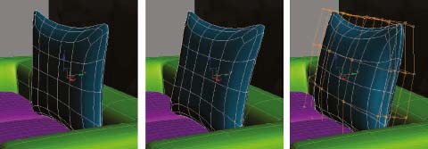
130. Create a mirrored copy of the pillow and adjust the FFD modifier’s control points to make the 2nd pillow appear unique. To achieve a more realistic look, I suggest making the 2nd pillow slightly overlap the 1st pillow, either in front or behind. I also suggest taking the extra few seconds to rotate the front pillow so it appears to be leaning on the pillow behind it. The next illustration shows how your pillows might appear. As an additional note, if you created your initial plane too large and the two pillows do not fit properly, a simple adjust to scale should suffice.
131. Save your scene.
6. Modeling the throw pillows
132. Continue from the previous step or open the file ch06-05.max.
133. Make an additional copy of the last pillow you created and hide all other objects in the scene.
134. Delete the MeshSmooth and FFD modifiers from the modifier stack.
135. Add another Edit Poly modifier, enter Polygon sub-object mode and delete the middle polygons, as shown in the left image of the next illustration.
136. Switch to Vertex sub-object mode and move all of the vertices in the right half of the pillow to the left so that the 2 parts are connected in the very center vertex. Use Endpoint snaps to snap the two center vertices together. The result should look like the middle image.
In the next step, we need to weld the left and right halves of the pillow together. But before this can be done, the same vertices on both halves of the pillow have to occupy the same space. There is a very easy way to make this happen. By applying a non-uniform scale of 0% along an axis, all vertices will be brought together to occupy the same axis.
137. Select all of the vertices that make up the middle row of vertices for both the left and right halves of the pillow, right-click the Non-Uniform Scale transform, and type a value of 0 in the X axis field. The result should look like the right image of the next illustration.
138. Weld the selected vertices together. This is an important step, because if the vertices are not welded together there will be 2 borders around the 2 halves of the pillow and when we use Border sub-object mode later to apply a decorative trim, the trim would be created around both halves rather than around the entire pillow.
139. Since the color of this throw pillow is the same as the back pillows, apply a new object color to the throw pillow.
140. Apply the MeshSmooth modifier with 2 iterations.
141. Switch to Perspective view.
142. Apply an 80% Uniform Scale to the throw pillow. In the original reference image, the throw pillows appear to be about 20% smaller than the back pillows. Reducing the size of the throw pillow is in order, and if you unhide the plane with the reference image, as shown in the left image of the next illustration you can get a better idea about exactly how much to scale the size down. Depending on how you created your original plane, you may need to scale your pillow a different amount.
143. Unhide all objects and use the Move and Rotate transforms to position and orient the pillow properly on the left side of the couch as shown in the middle image of the next illustration. Notice that this pillow should be leaning backward and slightly to the side. Like the previous pillows, it should be buried a small amount into the cushions.
Just like the back pillows, the throw pillows should have a small amount of deformation applied. Since applying a decent FFD modifier can be a tedious task, you might want to try borrowing the modifier from another object.
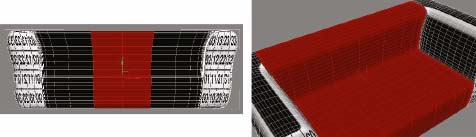
144. Select the right back pillow, right-click the FFD modifier in the modifier and select Copy.
145. Select the newly created throw pillow and on top of the MeshSmooth modifier you just added, right-click and select Paste. The FFD modifier you applied to the right back pillow is now applied to the left throw pillow, as shown in the right image of the next illustration. It’s a good idea to apply the FFD modifier of the right back pillow to the left throw pillow to prevent two adjacent pillows from appearing too similar. Nonetheless, you will probably need to tweak the control points of this throw pillow to make it fit the sofa properly.
146. As before, create a mirrored copy of the throw pillow, position it on the right side of the sofa, and copy the FFD (box) modifier from the left back pillow to the new throw pillow. Your scene should now look similar to the next illustration.
147. Save the scene.
7. Modeling the decorative trim piping
In this step, we are going to model the decorative trim piping that runs along the edges of the seat cushions, back pillows, throw pillows, and some edges of the sofa base.
148. Continue from the previous step or open the file ch06-06.max.
149. Use the Edit Poly modifier to attach the seat cushions to the base of the sofa to combine the three objects into one and then attach the back pillows and throw pillows together to combine the four pillows into one object.
150. Select and isolate the pillows.
151. Go to Border sub-object mode and click once at the edge of each pillow to select the border of each, as shown in the left image of the next illustration.
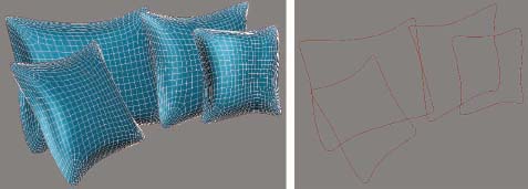
152. In the Edit Borders rollout, click the Settings icon to the right of the Create Shape button, accept the default Linear option and click OK to create a new shape with a generic name. A shape is created with 4 splines, as shown in the right image.
153. Close sub-object mode and select the newly created shape.
154. Open the Rendering rollout, activate the Enable in Renderer and Enable in Viewport options, and enter a Thickness value of 5/16”.
155. Exit isolation mode.
156. Select and isolate the base and seat cushions object.
157. While still in Perspective view, zoom in to the left side of the object as shown in the left image of the next illustration.
158. Switch to Wireframe mode. When you do, notice how busy the view is with so many edges visible. This is because when we attached the objects together a moment ago, the Edit Poly modifier must display all the edges that were previously hidden by the algorithms of the MeshSmooth modifier. We can alleviate this problem by changing a display setting.
159. In the Display panel, enable Backface Cull.
We need to create a trim feature as shown in the left image of the next illustration. To do this we will use the Create Shape feature again, but instead of clicking on a border, which we don’t have for this object, we need to select edges. And instead of selecting each individual edge we want included, we will use the Loop feature to quickly select multiple edges. However, when we do this, we will be selecting additional edges that shouldn’t be involved in the process. So once we use the Loop feature, we will have to deselect certain edges to make a shape similar to the left image of the next illustration.
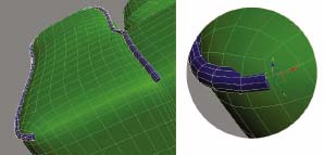
160. Select the 2 edges shown in the left and middle images of the next illustration and use the Loop feature to expand the selection around the couch in two different directions, as shown in the image on the right.

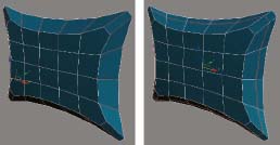
161. Use the Create Shape feature to create a shape from these edges with the default Linear option. When you do, the shape should automatically be created with a visible thickness.
162. Select and isolate the newly created shape as shown in the left image of the next illustration.
163. Temporarily disable the Enable in Viewport option.
164. Delete all of the segments of the spline we do not need, leaving the spline as shown in the left image of the following illustration.
165. Enter Vertex sub-object mode and delete the additional vertices that cause the spline to make a sharp corner as shown in the middle image. Delete as many or as few vertices as you want to create a nice spline for which the decorative trim will follow. In the image on the right you can see the result of deleting 5 vertices. Be careful not to delete too many, as this will cause the trim to not lay flush with the couch.

166. Enable the Enable in Viewport option again and make the trim thickness 3/8”.
167. Exit isolation mode and switch to Smooth+Highlights mode.
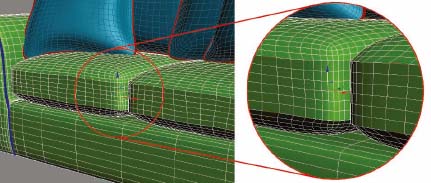
Notice that at the bottom of the sofa the trim does not look realistic because the end appears to be cut off. We need to make it sink into the surface of the sofa to look more natural.
168. Select the 2 vertexes at the ends of the spline and move them 1/8” in the positive Z direction and 1/8” in the positive Y direction, as shown in the left image of the following illustration.
169. Create a mirrored copy of the trim about the X axis and position it precisely on the right side of the sofa, as shown in the right image of the next illustration. Temporarily disabling the Enable in Viewport option in the Rendering rollout will help you place the shape better.
170. Select the 4 edges shown in the left image of the next illustration and use the Loop feature to grow the selection completely around the top and bottom of both cushions.
171. Just as before, create a shape from these edges and use the same settings to turn the spline into a renderable object, as shown in the right image.
172. Add the Edit Poly modifier to the newly created object and attach all other trim piping to it.
173. Save your scene.
8. Modeling the wooden feet
174. Continue from the previous step or open the file ch06-07.max.
175. Create a ChamferBox object with a length and width of 2 1/8” a height of 4 1/4”, and a fillet of 1/8”.
176. Apply the Taper modifier with an Amount value 0.87, as shown in the left image of the next illustration.
177. Position the object underneath the sofa in the appropriate place where you would expect the feet to be positioned.
178. Create 3 additional copies of the object and position them in their proper location at the other 3 corners of the sofa bottom, as shown in the right image.
179. Add the Edit Poly modifier and attach all 4 feet together.
180. Save the scene.
9. Texturing
In this step, we are going to assign material IDs to our model and then apply UVW mapping.
181. Continue from the previous step or open the file ch06-08.max.
182. With the exception of the background object, attach all scene objects together to make one object.
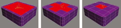
183. Apply the following material IDs to the following sofa elements: Material ID 1 – Wooden Feet; Material ID 2 - Base, seat cushion and back pillows; Material ID 3 - Decorative trim; Material ID 4 - Throw pillows.
184. With the model selected, go to the Utilities panel, click the Reset XForm button followed by the Reset Selected button.
185. Open the Material Editor and load the image numbers.jpg into the Diffuse Color channel of a material. This material will help us understand the size and positioning of the texture.
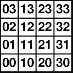
186. Apply the material to your sofa object and enable the Show Map in Viewport option. You will see that right now the texture is heavily distorted, as shown in the left image of the next illustration, which is a sign that the object does not have proper mapping.
Now we are going to apply UVW mapping to each element. Although we just attached all of the objects together to simplify the assigning of material IDs and the resetting of the XForms, we now need to detach the individual elements to make mapping easier.
187. Detach the wooden feet from the sofa, apply the UVW Map modifier with Box mapping and with a length, width, and height of 60”. This will be the size that the image we apply to the wooden feet represents in the real world.
188. Detach the sofa base and back and armrests (which are one element), and then select and isolate the detached object.
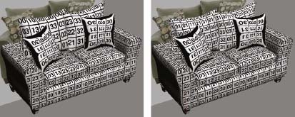
189. Switch to a Front view, select the detached object and enter Polygon sub-object mode.
190. With the Ignore Backfacing option disabled, use a crossing window to select the two middle rows of polygons that make up the base and back of the sofa, as shown in the left image of the next illustration.
191. In the Selection rollout, click the Grow button until all of the polygons that make up the front, back, and bottom are selected. As you can see in the right image, you should not select any of the polygons that make up the armrests.
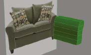
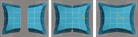
The following illustration shows the image that we need to apply to the couch base, cushions, and back pillows. This image is a very close representation of the material in the original image; however, you can always use Photoshop to carefully piece together parts of the original image to create an even more accurate material. The image is seamless so we can tile it as much as we want, and because the image is perfectly square, we can apply box mapping with minimal chance of distortion. The image appears to represent a real world size of about 16 inches, so this will be our mapping size.
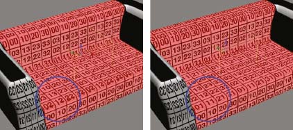
192. Switch to Perspective view and apply the UVW modifier with Box mapping and with a length, width, and height value of 16”. Notice that the texture is not mapped properly along the front of the couch, as shown in the left image of the next illustration. This is not a good place to show poor mapping.
193. Open the UVW Map modifier and move the gizmo in the positive Y direction until the numbers line up at the front of the couch, as shown in the image on the right. The numbers will not align properly on the back part of the couch where the pillows rest, but because this area will not be seen, it is not necessary to adjust any further. Note also that disabling Wireframe mode will allow you to see the map change in real time as you move the gizmo.
194. Add the Edit Poly modifier and return to Polygon sub-object mode. When you do, you should see the previously selected polygons still selected.
195. Press the keyboard shortcut Ctrl+I to invert the selection. This causes all of the polygons in the armrest to be selected.
196. Apply a UVW Map modifier to the selected polygons with Box mapping and a length, width, and height of 16”. The result should look similar to the left image of the next illustration.
197. Open the UVW Map modifier and transform the gizmo until you are satisfied with the mapping applied.
198. Exit isolation mode.
199. Detach the cushions and then select and isolate the cushions.
200. Apply a UVW Map modifier with Box mapping and a length, width, and height of 16”. Since the cushions have the same material as the couch base, we need to use the same mapping size we used a moment ago. Transform the mapping gizmo as necessary to achieve a seamless appearance to the cushions.
201. Exit isolation mode.
202. Detach the decorative trim and then select and isolate the trim.
203. Apply a UVW Map modifier with Box mapping and a length, width, and height of 16”. Since the trim is such a thin element and any fabric texture would be hard to recognize, we could really just apply a color to it rather than applying another UVW Map modifier. However, it only takes a moment to apply it and since 16” is as good as any size right now and since it matches the size applied to the rest of the couch, that is the size we are using here.
204. Exit isolation mode.
205. Select and isolate the back pillows.
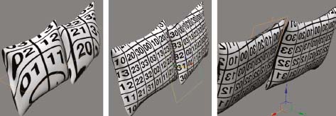
206. Apply the UVW Map modifier with Planar mapping and with a length and width of 16”. As you can see from the original reference image, the back pillows have the same texture as the rest of the couch, so we need to use the same mapping size. Notice, however, that the material is not oriented properly on the pillows, as shown in the left image of the next illustration.
207. Rotate the UVW Map gizmo around the X axis to align the gizmo with the front of the pillows, as shown in the middle image.
208. Add another Edit Poly modifier and rotate your view to see the back side of the pillows. Notice that the texture is flipped on the back side of the object, as shown in the right image.
209. Go to Element sub-object mode and select the two elements that represent the back side of the pillows.
210. With the two elements selected, apply the UVW XForm modifier and in the modifier’s rollouts enable the Flip option for the U Tile. This will flip the texture. Adding another UVW Map modifier would not have worked as well because you would have had to reorient the gizmo and adjust the mapping size all over again. The UVW XForm modifier is a great tool that allows us to modify the existing mapping without completely removing it beforehand.
211. Add another Edit Poly modifier to the object.
212. The next step involves the use of one the most widely adored tools in 3ds Max; the Unwrap UVW modifier. This modifier allows you to create complex mapping on an object and will be used to help bend the texture in the same way the structure bends. It will be discussed in much greater detail in Chapter 15.
213. Apply the Unwrap UVW modifier and click the Edit button within the Parameters rollout. This opens the Edit UVWs dialog box. You can zoom out within the dialog box to see the pillows in their entirety if you want. If you did not apply the Edit Poly modifier before this step, then the Unwrap UVW modifier would be applied to the last selected polygons, which we don’t want right now.
214. Press the keyboard shortcut Ctrl+A to select all of the vertices in the viewports. All of the vertices in the Edit UVWs dialog box are also selected.
215. From the Tools menu select Relax. This opens the Relax Tool dialog box. This feature will help bend the texture along the contours of the pillows.
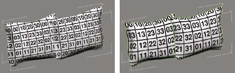
216. In the Relax Tool dialog box, use the Relax by Face Angles option along with an Iterations value of 1000, an Amount value of 0.5, and a Stretch value of 0.2. Click the Apply button to complete the command. The before and after results should look similar to the next illustration.
217. Close the Relax Tool and Edit UVWs dialog boxes.
218. Exit isolation mode.
The Relax feature is a great way to bend a texture along the structure of an object, but a downside to its use is that it always affects the texture size. In this case, the texture was enlarged about 30%, which is apparent when you compare the back pillows to the mapping on the couch. As before, we don’t want to do away with the mapping already applied, so we cannot add another UVW Map modifier. Instead, we will use the UVW XForm modifier again.
219. With the back pillows selected, apply the UVW XForm modifier with a U Tile value of 1.4, a V tile value of 1.4, and with the Apply to Entire Object option enabled. The before and after result should look similar to the next illustration.
220. Select and isolate the throw pillows.
221. Detach the left pillow from the right pillow and isolate the selection.
The next illustration shows the image created in Photoshop by piecing together parts of the original reference image. This image needs to be stretched over the entire length and width of the throw pillows, so the mapping gizmo needs to be set to match the size of the pillow once it has been oriented properly.

222. Apply Planar mapping to the pillow and rotate the planar gizmo to the surface of the pillow.
223. Increase the length and width of the gizmo so it covers the entire surface of the pillow, as shown in the left image of the next illustration.
224. Add the Edit Poly modifier and enter Element sub-object mode.
225. Rotate your view to see the back side of the pillows and select the back element of the pillow.
226. Keeping the selection active, apply the UVW XForm modifier and enable the Flip option for the U Tile. The back side of the pillow should now be oriented properly.
227. Add another Edit Poly modifier.
228. Apply the Unwrap UVW modifier and click the Edit button within the Parameters rollout.
229. Press the keyboard shortcut Ctrl+A to select all of the vertices in the object, and from the Tools menu, select Relax.
230. Use the Relax by Face Angles option with an Iterations value of 500, an Amount value of 0.5, and a Stretch value of 0.2. Click Apply to complete the command. The result should look similar to the right image of the next illustration. Although the size of the mapping was increased slightly, it is relatively insignificant and decreasing it here should not be necessary.

231. Close the Relax Tool and Edit UVWs dialog boxes.
232. Exit isolation mode.
233. Use the same technique to texture the right pillow.
234. Attach all objects together into one model. The result should look similar to the next illustration.
235. Save the file.
10. Applying materials
236. Continue from the previous step or open the file ch06-09.max.
237. Open the Material Editor and load the material library called Sofa.mat. This material library contains two materials; a standard material and a V-Ray version of the standard material. Both are multi/sub-object materials.
238. Apply the material named Sofa to the sofa in your scene. Because the material is a Multi/Sub-object material and because you have already created material IDs, each unique part of the sofa should now be textured properly. The next illustration shows the couch rendered in Scanline with no lights. The right image of Figure 6-2 shows the couch rendered in V-Ray.
239. This is the end of the exercise. If you want to view a completed version of the scene, open the file ch10-10.max.