
CHAPTER 8
Creating 3D Sites

THE CREATION OF 3D SITES offers all the challenges that come with 2D sites but with numerous additional difficulties. When creating 2D sites using the methods described in the previous chapter, you don’t have to worry as much about things such as gaps or holes between different elements, facets appearing on the various surfaces, adjacent faces overlapping, or any number of other problems that 3D terrain modelers have to contend with on a regular basis. You also don’t have nearly as much site data to interpret, prepare, import, and manage. For moderately sized projects, things like cleaning and preparing poorly constructed topographical lines could add hours to your work.
The goal of this chapter is to demonstrate techniques for creating 3D sites, address some of the most common problems 3D terrain modelers run into, and present some solutions to help solve those problems. To create a 3D site, you have to be able to create a 2D site, and knowing all of the techniques presented in the previous chapter are critical in the creation of 3D sites, as illustrated in this chapter. It will be necessary here to use tools such as the Boolean > Cut > Split, the Loft, the Sweep modifier, and numerous other features discussed in the last chapter. Rather than re-explaining these same features in this chapter, it will be assumed that you have a thorough understanding of all the tools needed to created 2D sites. This will allow the exercises to progress smoothly and quickly.
Elevation Data
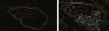
Site drawings usually originate from surveyors who provide information about the existing lay of the land to civil engineers, who in turn use that information along with the architect’s and owner’s intent to create a new design of the land. When a new design is created, perhaps the most critical information is the elevation data, which is provided in one of two ways; either with topographical lines, such as the left image shown of Figure 8-1, or with raw numbers, as shown in the right image.
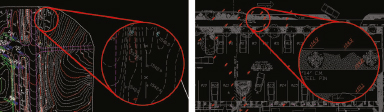
Figure 8-1. Elevation data through topographical lines (left) and raw numbers (right).
In most cases, when a site drawing only contains raw numbers rather than topographical lines, the changes in elevation are too minimal to warrant going to the trouble of creating the terrain in 3D. Notice in the right image of Figure 8-1 that the various numbers indicate only a few inches of elevation change. So in most cases, when 3D terrain is called for, you will be provided with a site drawing that contains topographical lines. Remember, however, that many architects create their own stripped down versions of site plans based on the civil engineering drawing they’re provided, and this type of information is not always placed on an architect’s site drawing.
Perhaps the biggest problem 3D terrain modelers face with topographical linework is that it’s not created in a way that’s suitable for work in 3ds Max. It’s usually not suitable because the last thing the civil drafter is considering when working on a drawing is how to help a 3D artist model the terrain in 3D. Notice in the left image of Figure 8-2 that there are structures that block the continuous flow of topographical lines. Trimming the topographical linework like this allows the structures to be displayed better in print, but when those lines are isolated (right image), it’s clear that there is a great deal of repair work to be done to prepare the linework for terrain creation. Fixing this problem requires you to connect the linework and weld end points, or to trace the linework instead. Which way you go simply depends on how many breaks there are and how many other ways the linework has been dirtied, such as overlapping lines, linework on wrong layers, and all the other things discussed in Chapter 2. Either way, a great deal of time is likely to be involved in preparing topographical linework for use in 3ds Max.

Figure 8-2. ‘Dirty’ togographical lines with annoying breaks.
Creation Methods
There are numerous ways to create 3D terrain in 3ds Max. Some are very precise, and some are just roughly approximated. Which method you use depends most heavily on the data you have to work with and the time you can afford to spend on linework preparation. If you have good, clean linework to work with, creating 3D sites can take just minutes. The techniques described in this chapter fall under one of two methods of creation; creation with the use of displacement or creation with the use of topographical linework.
Displacement
Displacement involves the use of a map to elevate select areas of an object’s surface. Pure black pixels mapped on the surface of an object will have no effect on the displacement of the object, while pure white pixels cause the maximum amount of displacement as defined by the displacement tool used to apply it.
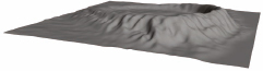
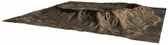
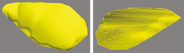
The left image in Figure 8-3 is the famous Diamond Head Crater in Hawaii, and the right image is a grayscale version of it created in Photoshop and used to displace the mesh shown in the bottom image. Creating this terrain in 3D is quite simple and a far better approach than trying to use topographical lines. Even if you did have very clean linework without all the problems that always seem to exist, creating this terrain with topographical lines is probably not the best approach. The size represented by the aerial image is 1.25 miles, and achieving the same kind of detail provided with image displacement would require so many individual lines with so many vertices that their use would probably overwhelm your system resources. Notice in the grayscale image, all the fine fractal-like detail coming out from the rim of the crater. This is simply not practical to incorporate into a series of splines, and even if you could, you would probably be waiting a lot longer for 3ds Max to complete the displacement.
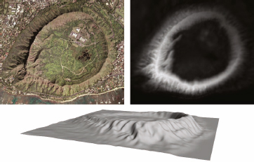
Figure 8-3. Using displacement to create the famous Diamond Head in Hawaii.
You could, however, use topographical lines as a guide with which to help you create the grayscale image, and in this way their existence would be worthwhile. You could simply load a screen shot of your linework into Photoshop and use the Magic Wand and Paint Brush tools to select and paint the various spaces between the lines in a way that mimics a CAT Scan. From here you could easily apply other tools to soften the transition and add further details into your image. This technique is very similar to painting maps onto objects using the Unwrap UVW modifier.
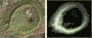
Figure 8-4. An example of using topographical linework to create a displacement map.
Now let’s look at different ways displacements can be applied. The main ingredient of any displacement is a map, and although there are several ways maps can be used to create displacement, some methods are clearly better than others.
Displacement mapping
Displacement mapping is a generalized term that is often used to describe the process of using a map to create displacement, but it actually refers to the use of a map in the Displacement channel of a material. There are two downsides to using a map in the Displacement channel. One is that it doesn’t automatically update an object in the viewports, and the other is that the displacement amount is guided only be the Amount value in the Displacement channel rather than by a real-world elevation value. Regardless, let’s see how it works so it can be accurately compared to the other methods we employ.
Creating terrain with displacement mapping
1. Open the file ch08-01.max. This scene contains one object; a plane with the default 4 length and width segments and a length and width of 1.25 miles; the approximate distance represented by the Diamond Head grayscale image that will be used to displace the plane.
2. Within the Material Editor, load the bitmap Diamond_Head_disp.jpg within the Displacement map channel and apply the material to the plane.
3. Enable the Show Map in Viewport option to make it easier to see how the displacement should occur. If you were to render right now, the object would not be displaced because a map in the Displacement channel cannot apply displacement by itself. It needs the Displace Mesh (WSM) modifier. This modifier is found in the World-Space Modifier section of the modifier drop-down list.
4. Apply the Displace Mesh (WSM) modifier. Notice that the plane is displaced slightly; however, without enough vertices, the displacement is unacceptable.
5. Go down in the modifier stack to the plane object and change the length and width segments to 50. The plane begins to take shape.
6. Switch to a Front view and use the Tape Measure tool to measure the total height of the land mass from the lowest point to the highest point. The height should be measured at approximately 817’. The true height of Diamond Head is 762’; however, with the use of displacement mapping, you cannot enter this value anywhere to produce the correct height. The best you could do is calculate the percentage change in height that needs to take place and enter a new value in the Amount field of the Displacement channel based on that percentage.
7. In the Material Editor, go up to the parent material, click inside the Amount field of the Displacement channel and type the keyboard shortcut Ctrl+N to open the Numeric Expression Evaluator.
8. Type 762/817*100 and press Enter. The Amount changes to 93, which is the value needed to lower the apex of the terrain to the approximate correct height. Notice, however, that the terrain didn’t change. Again, this is one of the shortfalls of displacement mapping.
9. Within the Displace Mesh Binding (WSM) modifier, click the Update Mesh button. The terrain should update and if you measure the height again, you should find that the apex is approximately 762’.
10. Save your file for use in the next exercise.
The Displacement modifier
Using Displacement mapping is certainly an option, but it provides no advantage over the better form of displacement, implemented through the Displace modifier. The continuation of the previous exercise illustrates this.
Creating terrain with the Displacement modifier
11. Continue from the previous exercise or open the file ch08-02.max.
12. Disable the Displacement Map channel within the Material Editor, and within the Modifier panel, click the Update Mesh button. The terrain should return to a completely flat plane.
13. Remove the Displace Mesh Binding (WSM) modifier and in its place, add the Displace modifier. The Displace modifier is really the best option for standard 3ds Max displacement. With the Displace modifier, we can now enter an exact value for the displacement height.
14. Enter a Strength value of 762’. Notice that the entire plane is elevated to this height. This is because there is presently no map loaded in the modifier to guide the displacement.
15. Drag an instance of the Diamond_Head_disp.jpg map from the Material Editor to the None button within the Map section of the Displace modifier. Now the terrain should appear as it did before with the Displace Mesh Binding (WSM) modifier applied. However, you can now change the elevation of the terrain in real-time by adjusting the Strength of the Displace modifier.
One important thing to remember with the Displace modifier is that the value you enter for the strength will result in that height when there are pure white pixels somewhere in the map that is applied. In this exercise, the very top of the crater was elevated to 762’ feet because the pixels on the corresponding part of the map were pure white. If the brightest pixels in the map only had a color value of 128 (halfway between pure black and pure white), entering a value of 762’ for the displacement strength would only yield a maximum displacement of 381’.
16. Press the keyboard shortcut 7 to turn on the Show Statistics feature. The total polygon count should indicate 5000 polygons. Remember from previous chapters that this is not really accurate. There are actually 2500 polygons and 5000 faces. Nevertheless, this is a relatively small number of polygons and we can certainly afford to use more to create greater detail.
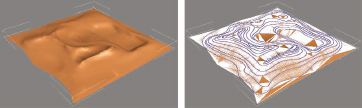
17. Render the Camera view so you can compare to the added detail the next step will create. The result so far should look like the left image of the following illustration.
18. Go down to the plane object in the modifier stack and change the length and width segments to 200. The terrain immediately updates to show much greater detail and the face count now sits at 80,000.
19. Render the Camera view again. The terrain should now look like the right image.
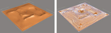
Notice that although the terrain now has much greater detail, it isn’t necessarily more realistic. The main reason is because of the excessive displacement in some of the sloping ridges that run down from the top. And the reason they exist is because of the drastic changes in color in the grayscale image used to create the displacement.

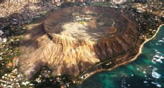
If you look at a perspective aerial of Diamond Head in the following illustration, you can see that the variance is not quite so dramatic. There is a lot of detail that would be nice to add; however, it would require you to use much greater precision during the manipulation of the original image, which you may or may not be willing to do. If you do, then increasing the face count of the object before the displacement is added might be the way to go. If you are not willing to manipulate the image as required, your next best alternative is to mitigate the variance by using the MeshSmooth or TurboSmooth modifiers. Each has its advantages and disadvantages, but they are minor and both will produce the exact same mesh.
20. Apply the MeshSmooth modifier to the terrain. I prefer the MeshSmooth modifier, because it won’t increase the face count in the viewport until you turn the object into a mesh or poly object.
21. Render the Camera view. Notice that there is no significant change to the terrain. The reason is because the terrain was already smooth and had too many vertices in place to allow for smoothing to occur over a larger area. The only way you can reduce the variance in the terrain is by reducing the original face count in the plane object.
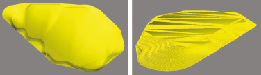
22. Change the length and width segments of the plane to 80. The result should look like the following illustration. The terrain doesn’t have the detail it had before, but it also doesn’t show the bigger problem of greater variance. It also uses only about 25,000 faces rather than 80,000.
23. Just so we can finish this exercise with one more touch of realism, load the bitmap Diamond_Head_diff.jpg into the Diffuse Color channel of the applied material and render the Camera view again. The result should look like the following illustration. If you want to see a completed version of this scene, open the file ch08-03.max.
As a final note about displacement, you can animate the strength of the displacement to create the effect of an object growing out of the ground, or the effect of the ground itself growing in height.
Topographical Lines
Although displacement provides a quick, efficient, and effective way of creating 3D terrain, projects don’t ever come with displacement maps. If you want one, you will need to create one yourself, and in many cases this is just not the most practical approach. The most common approach for creating 3D terrain is through the use of topographical lines.
Topographical lines, also referred to as contour lines or isolines, allow for very accurate terrain creation, but they come with two significant drawbacks. They usually require a great deal of preparation to use and require far more skill than simple displacement. In many cases, the linework is horribly constructed from a 3D artist’s point-of-view, because it often contains an enormous number of breaks to help display elevation data or other data critical to a civil engineer. Occasionally, you will find things like endpoints that don’t meet properly or poor layer management, but the most common problem, by far, is the break in the linework that civil engineers place in the drawings, as shown in Figure 8-2. The only solution to this problem is to fill in the gaps with your own new linework, and that is often an unavoidable situation that can take an enormous amount of time to complete.
In the following exercises, you will not be required to fill in the gaps of the topographical linework because this requirement, although very common, is a very simple task to complete that can require a great deal of time. Instead, we will jump right into the more difficult tasks of trying to solve the problems that really perplex many 3D terrain modelers. In the 1st exercise using topographical linework, we will work with a large area of land and attempt to create a decent looking terrain with a smooth appearance and with minimal polygons. In the 2nd exercise, we will work with a very small piece of terrain that will be seen up-close and will need to be created with great precision.
Creating large 3D terrain with topographical lines
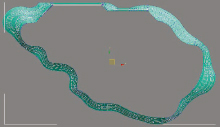
1. Open the file ch08-04.max. This file contains one editable spline consisting of numerous individual splines placed at their proper elevation. The task of filling in gaps, welding endpoints and placing the various splines at their proper elevation was already performed because of the simplicity and time involved.
2. Select the spline and from the Display panel enable Vertex Ticks. This option allows you to see just how highly dense the vertices in the splines are.
3. Use the Edit > Hold feature to save the scene in its current state.
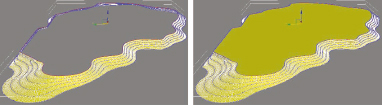
4. Select the Terrain feature from the list of available Compound Objects. Notice that the perimeter of the spline does not conform to the original rectangle that made up the perimeter, as shown in the left image of the following illustration. Also, there is a large amount of erratic shading and the object is plagued with a jagged appearance.
5. Press F4 to turn on Edged Faces mode. Notice the enormous number of faces, as shown in the right image.
6. From the Simplification rollout, enable Interpolate Points * 2. This improves the appearance of the perimeter of the terrain but worsens the problem of excessive faces. This is not the way you should attempt to improve the look of the terrain.
7. Use the Edit > Fetch feature to restore the object to its spline configuration.
8. Add the Normalize Spline modifier. This could take a few moments to add because of the large amount of vertices, but when it’s completed, notice that a new array of vertices are distributed per the default segment distance of 20 units. This creates far too many vertices so we need to increase the segment length.
9. Increase the Seg Length value to 200. This results in 1/10th of the previous number of vertices. More importantly, it will allow us to use other tools to smooth out the terrain while maintaining sufficient detail and accuracy.
10. Reapply the Terrain feature to the object. The terrain now appears to be structured much better than before, as shown in the following illustration. Toggle Edged Faces mode on and off to help see the object with and without edges displayed. Notice that the terrain stills lacks smoothness in many areas, as shown in the left image. It would be impossible to remove this smoothness by just adding the MeshSmooth or TurboSmooth modifiers because there are too many vertices in positions that can’t be adjusted. These modifiers only add vertices but cannot add them in a way their names imply. When character modelers create models, they have to create a basic structure with a very chiseled appearance. Adding too much detail too soon simply restricts the modifications that can be made later. You can see this if you try applying either of these modifiers right now. If you want smooth terrain, you will need to start with additional topographical lines around the problematic areas or create terrain with minimal polygons.
This next exercise demonstrates the need for precision and accuracy in 3D terrain creation.
Creating small 3D terrain with topographical lines
1. Reset 3ds Max.
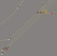
2. Use the Legacy AutoCAD format to import the drawing ch08-01.dwg. Ensure that objects are derived by layer and that the Convert to single objects option is enabled. This drawing contains the linework shown in the left image of the following illustration, which is part of the more complete site drawing shown in the right image. There is one layer of topographical linework, one layer representing pavers, and a third layer representing the curbs. The paver and curb linework will be used later, so for now we can hide these 2 objects.
3. Perform a Zoom Extents All and hide the objects 0-Site-Curbs.01 and 0-Site-Pavers.01.
There are 6 splines making up the topographical object, each of which needs to be placed at the proper elevation.
4. Change the Perspective view to an Orthographic view and switch to a single viewport configuration.
5. Zoom in closely, select the 0-Site-TopoLines.01 object and go to Spline subobject mode.
6. Leaving the outer spline at an elevation of 0’, move each inner spline upward 1’. The inner most line should be elevated 5 feet above the home grid.
7. Enter Vertex sub-object mode and weld all of the vertices in the object together. This should be something you should do every time you work on imported linework.
8. Enable the Show Vertex Ticks option from the Display panel.
9. Use the Edit > Hold feature to save this object in its current state.
10. Use the Terrain feature to turn the linework into a 3D mesh object. This object contains all of the same problems the terrain in the 1st exercise contained at the start, as shown in the following illustration. This object requires very precise creation because of its surrounding environment.
11. Use the Edit > Fetch feature to return the object to its spline configuration.
12. Add the Normalize Spline modifier with the default Seg Length value of 20.
13. Reapply the Terrain feature and the object should appear to be much smoother along the sides. However, it still contains erratic extra polygons along its base and the smoothing on the top is still unacceptable.
14. Switch to a Left view and add the Edit Poly modifier.
15. Enter Polygon sub-object mode and with the Window selection active (not the Crossing), select only the very top and very bottom polygons, as shown from the Perspective view in the left image of the next illustration.
16. Return to an Orthographic view and delete the selected polygons. The terrain should now look like the image on the right.

17. Enter Border subobject mode and click on the very top of the terrain to select the top border of the terrain.
18. Within the Edit Borders rollout, click the Cap button. This adds a single polygon covering the entire top of the terrain. This new polygon does not have the smoothing issues the deleted polygons had.
As it stands now, the terrain is completely accurate and has sufficient smoothing everywhere except along the border of the top polygon. This hard edge along the top is far too strong and must be smoothed out. Doing so with the terrain in its current form would be more difficult and time consuming than if the terrain was created strictly from 4-sided polygons. More importantly, making modifications after the basic structure is completed would be far more difficult with triangulated polygons than it would be with 4-sided polygons. Many 3D artists insist on creating their models strictly with 4-sided polygons because of the ease of modifying such an object versus an object created from triangulated faces. Because of the benefits of creating a mesh with 4-sided polygons, this section demonstrates the process of creating this same terrain object in this fashion. The process itself takes slightly longer than the process just used; however, the editing benefits are often worth it in the long run.
19. Use the Edit > Fetch feature to return the object to its spline configuration.
20. Select the terrain object and enter Vertex subobject mode.
21. Enable the Show Vertex numbers option.
22. Switch to a Top view.
23. Delete the 6 unnecessary vertices that lie on a straight line between adjacent vertices. These should be the vertices shown in the following illustration. These 6 vertices do nothing to define the shape of the individual splines of this object. You could also save yourself time in the process described in this exercise by deleting other vertices that aren’t needed, because they lie in a straight line with their adjacent vertices. However, do not bother deleting any other vertices at this time.
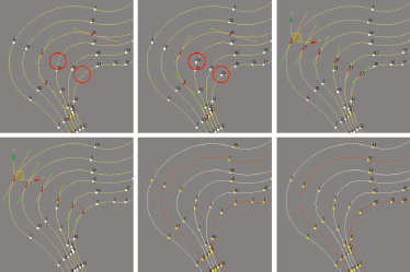
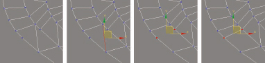
Preparing objects for completely 4-sided polygons requires a very strict arrangement of vertices. Each spline needs to contain the same number of vertices, and vertices with the same number need to be next to each other on the adjacent splines. To do this, we need to pick a starting point along all 6 splines and establish a first vertex. Notice in the top-left image of the following illustration that 4 of the 6 splines have vertices positioned next to each other. We will begin here and add vertices on the other 2 splines.
24. Zoom in to the top-left portion of the terrain object, as shown in the following illustration.
25. Within the Geometry rollout, click the Refine button and click on the 4th and 6th splines, as indicated by the highlighted areas in the top-left image of the following illustration. The result should be two additional vertices as shown in the top-middle image. These will be the 1st vertices of each spline.
26. Select the 6 adjacent vertices shown in the top-right image and click the Make First button. The result should look like the bottom-left image.
Now we have to make each spline run in the same direction. Notice that 4 of the 6 splines are currently running counter-counter, but that the 2nd and 6th splines are running in the opposite direction. This is just a result of the order in which the lines were drawn or edited in AutoCAD.
27. Switch to Spline sub-object mode and select the 2nd and 6th splines as shown in the bottom-middle image.
28. Within the Geometry rollout, click the Reverse button. All 6 splines should now be running in the same direction; counter-clockwise. This is shown in the bottom-right image.
Notice in the left image of the following illustration that the 4th spline has a 2nd vertex position very close to the 1st vertex. To make this entire process work, we have to leave this vertex where it is, because it is critical to defining the shape of its spline; however, we also have to have the 2nd vertex of each of the other 5 splines be positioned adjacent to it, rather than far away from it as they currently are.
29. Switch to Vertex sub-object mode and use the Refine tool again to add a row of #2 vertices just below the 1st vertex of each spline, as shown in the middle image of the following illustration.
Now we have to repeat this process with the next vertex; the #3 vertices of each spline.
30. Using the 3rd spline as a starting point, add additional #3 vertices on all the other splines, so you create a row of adjacent #3 vertices, as shown in the right image.
31. Repeat this for the row of #4, #5, and #6 vertices, as shown in the right image. After completing row 6, notice that the 5th spline (2nd from top) contains 2 vertices that serve no purpose because they don’t define any curvature. Leaving them in would only mean that we have to create other adjacent vertices on the other 5 splines.
32. Delete these additional 2 vertices found on the 5th spline.
These last few steps must be repeated for the entire object. This process can take 10-20 minutes because you will need to add a couple of hundred vertices to make each vertex be a part of a row of side-by-side vertices. However, once completed, it will be very quick and easy to turn this object into an object made up of 4-sided polygons.
33. Add vertices to each of the 6 splines so that each spline contains the exact same number of vertices and so that each row of vertices is lined up in a straight fashion, as shown in the next illustration.

34. If you want to continue from this point on using an already prepared file, open the file ch08-05.max.
35. Add the Turn to Poly modifier. This modifier will help us create 4-sided polygons. Notice the large number of vertices that are generated. This happens because of the interpolation in the base spline.
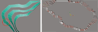
36. Enable Smooth + Highlights mode. When you do, you can see that 3 portions of the terrain are renderable and 2 are not. This always happens when you turn a series of closed splines into a renderable object.
37. Change the object’s color to something that allows the individual segments to be seen easier, such as a blue-green color.
38. Within the Turn to Poly modifier, enable the Limit Polygon Size option and set the Max Size value to 4. These changes prevent polygons with more than 4 sides from forming. The difficult part is to make 3ds Max create 4-sided polygons rather than 3-sided. Unfortunately, because of the large number of vertices generated from the interpolation in the base spline, it is too difficult for 4-sided polygons to be generated. You could improve the chances by making the interpolation much lower, but the interpolation will simply change the spacing between vertices in a disproportionate fashion. Therefore, we cannot use interpolation.
39. Go down in the modifier stack to the base spline and change the Interpolation value to 0. This removes all curvature in the spline.
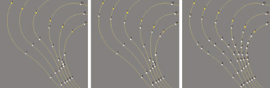
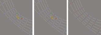
40. Return to the Turn to Poly modifier and assuming you created your spline properly, you should now see numerous 4-sided polygons everywhere, as shown in the left image of the following illustration. If you refined your spline in a way that 3ds Max couldn’t deal with properly, you will see 3-sided polygons, like the one shown in the left image. If you are working from the file ch08-05.max, there will be 1 individual segment that was not created properly, as shown highlighted in the left image. This edge will be dealt with momentarily.
You could apply the MeshSmooth modifier right now and get a nice smooth-looking mesh with 4-sided polygons everywhere; however, the lack of interpolation in the base spline will cause the resulting mesh to be generated slightly off from the location of the original splines. If you do not need great precision in your terrain, this would probably be the best option right now. In this scene, however, we need a very precise model. Therefore, we will need to add vertices in the base spline. We can’t do it with interpolation, so the only other option is to manually divide the segments that need extra vertices badly. The more curvature a segment has, the more we will need to add vertices. Just remember though, that the more vertices we add, the less likely we will see 3ds Max generate 4-sided polygons. This means that we want to add just enough to retain the original shape of the splines.
41. Return the interpolation of the base spline to 16. This will help show what edges need to be divided.
42. Enter Segment sub-object mode and select all of the segments that have a significant curve and a large space between the vertices that define the curve. This is demonstrated in the right image of the following illustration. Do not select edges that are very short, as dividing these will not be important and will only make it harder to generate 4-sided polygons. Also, switching to a Fence Selection Region and using the Crossing selection tool will make selecting multiple segments much easier.
43. If you want to continue using the selected edges shown in the right image of the previous illustration, you can use a named selection set that has already been saved with this file called curves. Simply select this from the Named Selection set drop-down list.
44. Change the interpolation of the object to 0 to remove all curvature.
45. Enable the Show end result on/off option in the modifier stack. This will show you the result of the Turn to Poly modifier even when you are working within the base spline. This is shown in the left image of the following illustration.
46. Divide the selected edges one time and analyze the resulting mesh. The result should look similar to the middle image. Notice that there are a couple of additional problem edges generated as a result of this division.
47. Divide the selected edges a second time. The result should look similar to the right image. This amount of division should be enough to ensure that the final mesh stays close enough to the shape of the original linework. You could divide further, but it would result in more work with negligible improvement.

48. If you want to continue with an already prepared file, open the file ch08-06.max.
49. Press the keyboard shortcut Ctrl+V to make a clone of the object using the Copy option.
50. Enter Spline sub-object mode, select the 1st and 6th splines (bottom-most and top-most) and delete these 2 splines.
51. Return to the Turn to Poly modifier and the 2 missing portions of the terrain should appear as shown in the following illustration.
52. Add the Edit Poly modifier and attach the first terrain object to the second.
53. Enter Vertex subobject mode and weld all of the vertices of the new object.
54. Enable Wireframe mode and zoom in-to any problematic areas of the object, such the one shown in the following illustration.
55. Enter Edge sub-object mode and select one of the misaligned edges, such as the one shown in the middle-left image.
56. Within the Edit Edges rollout, click the Remove button. This removes the selected edge. Unlike the delete command, which deletes the vertices it connects, the remove command does not delete anything else.
57. Enter Vertex sub-object mode and select the two vertices that have no edge running between them, as shown in the middle-right image.
58. Within the Edit Vertices rollout, click the Connect button. A new edge is created between the two vertices.
59. Repeat this process everywhere you have a misaligned edge. You can remove multiple edges at a time and connect multiple vertices (that are part of the same row) at the same time, such as those shown in the following illustration. Only after there are no misaligned edges can you continue with the next step.

60. If you want to continue with an already prepared file, open the file ch08-07.max.
61. When you think you have connected the last set of vertices, return to Edge sub-object mode and select any edge that runs up and down the slope of the terrain (not one that runs laterally or horizontal to the ground). An example is shown in the left image of the following illustration.
62. Within the Selection rollout, click the Loop button to select all of the edges that are connected and make up an individual row.
63. Click the Ring button to select all the edges that run laterally around the terrain. If all of the edges running up and down the slope of the object are selected, as those shown in the right image, then you know you are finished with the alignment of the edges. If the Ring command did not cause all of these edges to become selected, you have a misaligned edge somewhere in the object.
64. Close Edge sub-object mode and switch to an Orthographic view as that shown in the next illustration.
65. Enter Border sub-object mode and use the Cap feature to add a top to the terrain as we did before.
66. Close Border sub-object mode.
67. Within the Edit Geometry rollout, click the MSmooth button. This turn breaks each 4-sided polygon into 4 smaller polygons of equal size, as shown in the middle image. You cannot just add the MeshSmooth modifier to achieve the same effect. Notice that the top polygon has been changed in a negative way.
68. Undo this last command.
69. Enter Polygon sub-object mode and select the polygon that makes up the entire top of the terrain object, as shown in the left image of the following illustration.
70. Within the Edit Polygons rollout, click the Settings icon immediately to the right of the Inset button and create an inset 12 inches from the perimeter of the top polygon, as shown in the middle image.
71. Delete the selected polygon that makes up the top of the terrain. Next, we’re going to apply the MSmooth feature again; however, we needed to add an inset row of polygons as we just did because we need a horizontal set of polygons to make the smoothing action of the MSmooth feature create a complete bend around the rim of the terrain. Otherwise, we would still be left with an abrupt edge as before.

72. Close Polygon sub-object mode and then click the MSmooth button inside the Edit Geometry rollout. The terrain should appear much smoother, as shown in the left image of the following illustration.
73. Click the MSmooth button again and the terrain should be even smoother, as shown in the middle image.
74. Enter Border sub-object mode and select the border along the top of the terrain.
75. Within the Edit Borders rollout, click on the Cap feature to create another top for the terrain.

76. Render a close-up Perspective such as that shown in the left image of the following illustration, to see what the terrain looks like at this point. You should see a noticeable facet look to the terrain along the top.
77. Apply the Smooth modifier with the Auto Smooth option and render the view again. The facets should completely disappear, as shown in the middle image.
78. Render the entire terrain to see what it looks like. It should look similar to the right image.

At this point, we are finished with this phase of the terrain’s construction and the only thing that remains to be done is to tweak the somewhat perfect look of the terrain and make it a little more believable by adding some imperfections. This can be done with numerous different modifiers, most of which you should be familiar with. These include the FFD, Edit Poly Soft Selection, Edit Poly Paint Deformation, Noise, Relax, Wave, Ripple and many more.
Keep in mind a couple of very important points with any of these tools. If you want to apply these modifiers to the entire object, you will need to detach the top polygon, subdivide it to create sufficient polygons with which to apply the modifiers, and then reattach these polygons and weld endpoints. If you want to apply these modifiers to specific parts of the terrain, don’t forget to take advantage of the great sub-object selection tools within the Edit Poly modifier; such as Loop and Ring, as well as the feature that allows you to translate a selection by holding down the Ctrl key while simultaneously clicking on one of the other sub-object icons (not the word in the modifier stack but rather the icons below the stack). With these tools, selecting the exact sub-objects you want becomes easy.
Also, don’t forget to use the View Align and Grid Align features once you’ve applied modifiers to your terrain. For example, if you apply the Noise modifier to the entire object gaps will form along the bottom of the terrain where it meets the surrounding terrain. However, if you then select the entire bottom set of vertices, switch to Top view and click the Grid Align button, all of the disturbed vertices will return to the home grid.
If you want to experiment more with this current scene using an already prepared file, open the file ch08-08.max. Also, try practicing the techniques described in the previous chapter on 2D sites and use those to create the other elements depicted in this project’s linework. The linework that was hidden at the beginning of the exercise would be a great place to start. When these elements are created, you could have something that looks like the following illustration. If you want to investigate this completed scene, open the file ch08-09.max. As a side note, the walkways in this project contain stairs in real life, which is why you see such large and unrealistic inclines on the walkways up to the pool area. Adding this type of element is best once you’ve already prepared the model as shown in the following illustration.

The remaining two sections of this chapter deal with some additional issues concerning 3D terrain that should help you in a number of different situations not yet addressed.
Adding Site Elements to 3D Terrain
The techniques you use to add site elements to 3D terrain should be very similar to the techniques used for 2D terrain, with a few specific differences. The following section lists some of the major types of site elements and a recommended approach for their creation.
• Roads – Use the Boolean > Cut > Split feature to cut your roads out of the terrain just as you do with 2D terrain.
• Curbs – Once you create your roads, convert the roads to an Editable Mesh and use the Select Open Edges and Convert to Shape features to create a spline that exactly follows the sides of the road. You can then use the Loft or Sweep features to create your curbs and have them follow the contour of the terrain.
• Sidewalks – Use the Boolean > Cut > Split feature to cut out the sidewalks and then use the Extrude feature within the Edit Poly or Edit Mesh modifiers to create thickness to the object.
• Pavers – Use the Boolean > Cut > Split feature just as with 2D terrain.
• Parking Lines – Unlike 2D terrain, where the parking lines can float slightly above a parking lot, parking lines on 3D terrain must be cut out of a parking lot to prevent them from being buried in it. You do not need to worry about disabling the Shadow Casting feature for parking lines with 3D terrain.
• Mulch – As with parking lines, mulch must be cut out of 3D terrain to prevent it from being buried in it.
• Bodies of Water – Since water is always going to be flat, it is important to remember that if you decide to cut out your body of water from 3D terrain, you will have to use the View Align or Grid Align features in Top view to make all the affected vertices return to the same plane.
• Grass – The grass object is often the first object created from which others are cut out. Therefore, you must always ensure to start with enough polygons to allow for enough accuracy in your cuts and enough detail in your 3D terrain. However, assuming that you will be using smoothing tools with your terrain, you should also be careful not to create too many polygons initially, which would reduce the program’s capability to generate larger curvature between vertices.
Controlling the Bumpiness in 3D Site Elements
If you cut an element of out 3D terrain and want to reduce the bumpiness of that object, such as for a road or sidewalk running through rough terrain, you can make the object flatter without negatively affecting the terrain around it. The following exercise demonstrates how to do this.
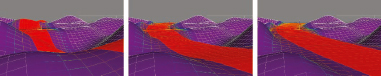
1. Open the file ch08-10.max. This scene contains two objects; a high density plane to simulate a terrain of rolling hills and an object that will be cut out of the terrain to simulate a road running over the hills.
2. Select the plane object and use the Boolean > Cut > Split feature to cut the road out of the plane, as shown in the left image of the following illustration. Once the cut is made, do not detach the road.
3. Add the Edit Poly modifier to the compound object and enter Polygon sub-object mode. The road polygons should be automatically selected.
4. Within the Polygon Properties rollout, change the material ID of the selected polygons to ID #2.
5. Enter Vertex subobject mode, press Ctrl+A to select all the vertices and weld all the vertices of the object back together. This causes the object to return to having just one element.
6. Enter Polygon sub-object mode and press Ctrl+D to deselect all polygons. Unless you created a unique material ID for the road polygons, there wouldn’t be a quick and easy way to select all the road polygons again. It is important to set up material IDs like this, in the event you need to return to sub-objects that have deselected, and cannot benefit from multiple elements due to the welding of vertices.
7. Use the Polygon Properties rollout to select all the polygons with material ID #2.
8. Enable Soft Selection with a Falloff value of 5. If you were to apply a modifier to these selected polygons now, the soft selection would still affect the surrounding polygons. Also, you could switch to Top view right now and use the View Align or Grid Align features to make all the selected polygons align to the same plane. If you did, the soft selection will still affect the surrounding polygons. Instead of doing any of these things, let’s do something even easier.
9. Use the transform gizmo to apply a non-uniform scale along the Z axis. You can apply a moderate scale as shown in the middle image of the following illustration, which leaves some deformation in the road, or apply a 100% scale downwards along the Z axis to make the road completely flat, as shown in the right image. Had we not used a soft selection, the change from the road to the surrounding polygons would be quite unrealistic.
Summary
When you know some effective techniques, creating 3D sites can be one of the most enjoyable areas of a 3D visualization project. However, if you aren’t familiar with some effective techniques, it can be one of the most frustrating areas. Numerous tools in 3ds Max were developed specifically to aid in the creation of the very objects this chapter is based on. These include things like the ShapeMerge and Conform. Both of these tools might seem at first to be ideal 3D site creation tools, but both have major issues that make working with them more trouble than they are worth. There are far better tools to use that weren’t even created specifically for 3D sites, and more so than most areas of 3D visualization, the techniques you develop are probably limited more by your imagination than by the tools available. It probably won’t be too many more releases before Autodesk makes 3D site creation even easier with more dedicated tools; but in the meantime, we must rely on our imaginations more than the tools they created specifically for our type of work.