CHAPTER 3
Creating Walls, Windows, and Doors (Part I)
IT SEEMS THAT SINCE THE first days of 3D visualization, no other architectural element has garnered more attention than the ‘wall’. One of the most commonly asked questions between fellow 3D visualization artists is, “How do you create your walls in 3D?” The question is bound to be answered a number of different ways depending on who you ask and their experience level, but the question is so important to so many of us because the walls are usually the first part of a building that we create, and arguably the most important. It is, in some ways, the real foundation on which other building elements are added. And unlike other critically important scene elements like vegetation, cars, backgrounds, etc., walls leave no room for artistic interpretation, and neither do the objects we place in or on our walls. Extraneous objects, like cars, are certainly important but are usually not the focus of a project. In most cases, a building is the focus of a project and although our choice in cars may not appeal to our clients, it is certainly understood that these types of objects are open for some degree of artistic interpretation, and as such, disapproval is usually not considered an error. Walls, on the other hand, need to be created with precision and any deviation from the data provided in the architectural drawings is usually considered erroneous. It’s no wonder then why so many 3D artists are interested in the techniques with which others create these critically important object types.
But the creation of walls is of great interest because of their importance to a scene and the attention to detail that’s needed to make them, and because of the time needed to make them properly. Depending on the type of building being created, the walls may consume more than half of the time needed to complete the entire building. So the various techniques available to create this type of object are, and probably always will be, of great interest to others. The next chapter, which is Part II of this discussion, is dedicated to illustrating what I believe to be the best, fastest, and most efficient way of creating walls; using the Loft and ProBoolean commands. But because there are other widely used methods for creating these object types, I thought it would be appropriate to discuss these other methods many veteran users prefer. Throughout both of these chapters, I will draw comparisons between all of these widely used techniques so you can decide for yourself which method works best for you.
There are four primary methods 3D artists use to create walls for a 3D scene. Some artists use a combination of two or more of these methods, but the four primary methods of creation are as follows:
• BIM software
• The Extrude modifier
• Edit Poly modifier
• The Loft and ProBoolean commands
Creating Walls with BIM Software
In the early days of 3D visualization, a few software titles appeared that used a modeling technique known as BIM, or Building Information Modeling. The term is used to describe software that allows a user to create structures in 3D while simultaneously allowing the generation of key building information for construction drawings. For example, after placing 20 different doors in a building, the software would allow the user to click a few buttons and create a door schedule that would automatically list the details of all 20 doors, such as masonry openings, door heights, paint color, etc. This door schedule could then be easily placed in the construction drawings and used by the contractor creating the real building. Examples of this kind of software include Architectural Desktop and Revit.
If you work in an architectural office or if you’re in the business of creating construction drawings (in addition to 3D visualizations), then using BIM software to generate building models that can be imported into 3ds Max is certainly a worthy approach. Many 3ds Max users rely on the flexibility of design changing and the ability to quickly generate construction drawings that BIM provides. As long as you are aware of the powerful modeling tools available in 3ds Max and their own inherent flexibility toward change that they offer, then you can make an informed decision as to how much to rely on your BIM software to generate your building models. But if you are not aware of what these 3ds Max tools can do, the speed at which they can do it, and their ability to accommodate design changes it would probably be a good idea to look closely at the techniques outlined in this chapter.
In the first few years of introduction, BIM software did not receive a warm welcome. It was widely looked upon as weak, slow, and difficult to understand by even the most receptive users – myself included. During my years as a draftsman, I spent an incredibly large amount of time week after week trying to make the BIM software work in an efficient and cost-effective manner. But no matter how hard I tried, the software simply wasn’t capable of supporting our office’s needs to produce good working construction drawings while simultaneously allowing us to create our drawings in 3D. After a very long and painful trial period, our office abandoned our BIM software, as did many other offices in the same position. Today the outlook for BIM is far more promising, and the ability to generate accurate models and import them into 3ds Max is quite effective. Figure 3-1 shows a screen shot of Architectural Desktop 2005 and provides a small peek at the power and flexibility available with the software. Incidentally, the inset rendering was not created in Architectural Desktop.

Figure 3-1. Architectural Desktop 2005 with its powerful BIM features.
Although it’s quite advantageous to use and import models already constructed with BIM software, there are some definite drawbacks to this approach. One of the most frustrating aspects of working with imported models is the need to keep reapplying the same mapping coordinates over and over. Another is that random faces are often facing the wrong direction for no apparent reason, and the result is a building that appears to have holes in it. Even if you render with 2-sided materials, this doesn’t make viewing your models in a viewport any easier. Imported parametric models also tend to consume more RAM and be more of a strain on the graphics card, because of the inherent nature of the BIM software to create faces on an object that could not possibly be visible. Yet another frustrating aspect of using BIM is the ever increasing complexity of the software and the greater time needed to learn the additional features that come with each new release. The techniques of modeling in 3ds Max outlined in this chapter, on the other hand, have changed very little year to year. And perhaps the most frustrating aspect of using BIM is the time it takes to generate all the unique window and door styles when it seems that no two projects ever use these same styles without some degree of tweaking.
So if you are aware of all the advantages and disadvantages of modeling with 3ds Max and BIM software, you can at least make a good decision as to which is best for you. If you decide to start or continue using BIM, you can still take advantage of the 3ds Max tools to add certain details to your buildings, such as trim, banding, or roof tiles.
Creating Walls with the Extrude Modifier
The Extrude modifier has been a staple in the diets of many 3D users since the first days of the software. While not as powerful as many other modeling tools, it is still a favorite among many 3ds Max users today because of its simplicity and ease of use. In the DOS days of 3d Studio, this feature was used to some degree by virtually everyone needing to construct a building in 3D. Today its use is far less widespread, but many users still rely on it solely or in conjunction with one of the other techniques outlined in this chapter. At 3DAS, we still use this technique quite regularly, because under certain situations this technique itself cannot be rivaled. An example of just such a situation is the wall shown in Figure 3-2.
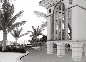
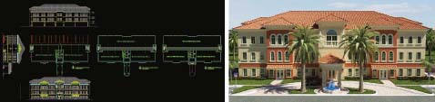
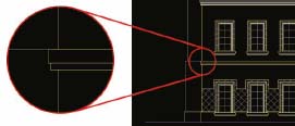
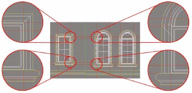
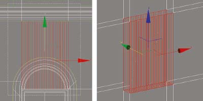
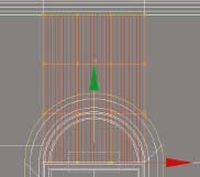
When used to create walls, this modifier is usually implemented by creating closed splines that mimic the outline of some part of an elevation, and extruding those splines along the X or Y axis. By creating the linework for door and window openings, you can simultaneously add these features to your walls with very little additional work. Even creating rounded windows and doors, curved arches, or any number of complex wall styles is quite simple and straightforward using this method. Figure 3-2 shows an example of this modifier at work. The top-left image shows the original Auto-CAD linework, the top-right image shows the isolated closed spline created for one of the walls, the bottom-left image shows the same spline imported into 3ds Max and extruded 8 inches, and the bottom-right shows the completed 3D rendering of the same project. Once the main wall component is in place, you can use the Extrude modifier to add other elements such as trim, banding, medallions, and even the windows and doors that fit within the initial extrusion. For example, if you want to add the trim along the bottom of the arch entry walls, simply create a rectangle in top view by snapping end points to the newly extruded wall, add the Edit Spline modifier, create an outline of approximately 1-inch in Spline sub-object mode and extrude the spline to the necessary height.
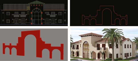
Figure 3-2. Building walls piecemeal with the use of the Extrude modifier.
So by using the Extrude modifier alone, you can construct a building in a relatively short amount of time. And while for most walls it doesn’t offer the speed that can be achieved with the Loft and ProBoolean features, the Extrude modifier is very simple, highly accurate, and moderately flexible. When used in conjunction with the Loft and ProBoolean, its use becomes even more practical.
Creating Walls with the Edit Poly Modifier
The Edit Poly modifier is arguably the single most important tool in 3ds Max for many users in many different industries. For some, this modifier is the backbone of the modeling portion of every project, and for others it is nothing more than a tool used to do a few quick things here and there. Whatever your choice, the Edit Poly is certainly one of the most powerful features available for modeling and you should at least be familiar with what it can do.
The Edit Poly modifier is also the backbone of a multi-industry wide technique known as box modeling. Box modeling is simply the technique of modifying a lowly detailed object into a highly detailed object. In fact, the term ‘box modeling’ comes from the technique of crafting intricate models out an ordinary box. The primary function of this technique is the extruding and scaling of the edges and polygons that make up an object, while a secondary function of this technique is the subdividing of these edges and polygons. With these two functions, the box modeler can create just about any object imaginable. This technique is used in the entertainment industry to model such objects as characters and vehicles, and in many cases, the user starts with nothing more than this simple primitive. In the architectural industry its use is just as far reaching and it is widely lauded in the creation of numerous architectural elements. In Figure 3-3, you can see how using this feature allows the user to start with a single polygon and end up with a highly detailed towel.
Figure 3-3. The Edit Poly feature used to turn a single polygon into a highly detailed towel.
In the upcoming chapters, you will see demonstrations and tutorials where this tool is used in the creation of everything from furniture to roofs to 3D sites. In the remainder of this chapter, however, its coverage is limited to a discussion on walls, windows, and doors.
So just how fast and easy is it to model these object types using the Edit Poly command? Well, if you rely on the Edit Poly for the majority of your modeling rather than just using it on occasion to make a few modifications here and there, then I would argue that you aren’t working at top speed and you’re doing things the hard way. In this chapter and the next are two exercises that help demonstrate the benefits and drawbacks of using the Edit Poly command for wall modeling versus using the Loft and ProBoolean commands. In the first exercise, found in the remainder of this chapter, we will use the Edit Poly command as the primary modeling tool. In the second exercise, found in the next chapter, we will use the Loft and ProBoolean commands. After conducting both exercises, you should have a fairly good idea of how each method works and which method is the most efficient.
As you have undoubtedly already read, AutoCAD drawings are a very important part of most 3D visualization projects. However, not all 3ds Max artists have AutoCAD and not all want to be forced to purchase this additional software. Because of this, there are two very different ways that 3ds Max artists use AutoCAD drawings to help guide their modeling in 3ds Max.
The best method, I firmly believe, is to prepare and import the necessary linework in AutoCAD as described in Chapter 2. This method allows you to immediately use the 2D linework to create 3D models rather than having to create new linework inside 3ds Max. It also means that you can carefully inspect and edit the linework inside AutoCAD using many of the program’s features that make this type of work so much easier than inside 3ds Max. This method of course requires you to own the software, but the bottom line is that if you do, you can take advantage of the many techniques described throughout this book that you would otherwise not be able to do without additional work inside 3ds Max.
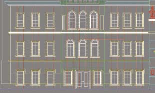
The second method in which many 3ds Max artists use AutoCAD drawings is to import, link, or XRef drawings into 3ds Max so you can use the linework as a background with which to trace new linework, or with which to guide how you model your individual objects. These drawings can be elevations (as shown in Figure 3-4), floor plans, or any other drawing that provides useful information about the structure you are modeling. With this method you have an exact visual reference that shows you exactly where each window should be placed, exactly where each reveal line should be located, or exactly where the top of each roof extends. By using the Edit Poly tool on an object, you can enter a sub-object mode and move, rotate, or scale individual sub-objects until they are lined up exactly with the background linework. Many 3ds Max artists use this method even when they have AutoCAD at their disposal, but as a matter preference, I believe this method is best suited for checking the work you do with other methods and for small occasional edits.
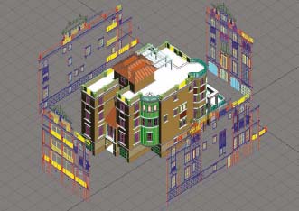
Figure 3-4. An example of using imported, linked, or XRef’d linework as a background for modeling.
So let’s run through the first exercise and see how the Edit Poly can be used to model walls. To provide a fair demonstration of the two methods of using AutoCAD linework as just described, the exercise will incorporate steps for using both methods. As an additional note, as mentioned in the previous chapter on preparing linework, many of the exercises in Parts 2 and 3 of this book will pick up where the last chapter left off. This means that many of the exercises will start by importing AutoCAD linework that has already been prepared using the techniques discussed in the last chapter. In the case of this first exercise, we will use cleaned and prepared AutoCAD linework for both methods of using AutoCAD linework, as just described.
Wall, Window, and Door Modeling – Part I (The Edit Poly)
In Part I of this two-part wall modeling exercise, we will use the Edit Poly as the primary modeling tool to create walls, as well as the windows and doors that lie within them. If you do not have AutoCAD, simply read step 1 for reference and proceed to step 2.
1. Open the AutoCAD file, ch03-01.dwg. This is a drawing of the medical office building shown in the next illustration called Olympic Park, whose linework has already been prepared by the guidelines specified in Chapter 2. You will be asked to refer to this drawing on a few occasions to complete this exercise properly.
2. Reset 3ds Max.
3. Change the units of this new scene to U.S. Standard, Feet w/ Decimal Inches and with Default Units set to Inches. If you do not wish to work in U.S. standard you will have to convert the units prescribed in this exercise.
4. In the System Unit Setup dialog box, ensure that the System Unit Scale is set so that 1 unit = 1.0 inches.
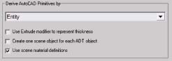
5. Import the file ch03-01.dwg using the AutoCAD DWG file type and the option to derive objects by Entity, as shown in the next illustration. In most tutorials in this book, you will be asked to use the Legacy AutoCAD file type because the AutoCAD DWG file type will often, and inexplicably, replace Bezier vertices with Bezier Corner vertices, thereby ruining the linework. This does not always happen but when it does, you can simply use the Legacy AutoCAD file type and curves will import properly. The downside to the Legacy AutoCAD file type is that it can take a long time to import a large drawing. Another very important thing to note is that the Entity option needs to be used, regardless of which file type is imported. This allows all of the individual lines, or entities, to be imported as individual objects rather than being grouped together. Because of this, the individual elevations can be repositioned, as we will see in an upcoming step. However, the Entity option comes with a warning that can actually be seen in the 3ds Max help files. In the help files, it says Warning: This option has the potential to create an enormous number of objects in your scene. It is only because of this side effect of using this option that the Legacy AutoCAD file type may be difficult to use. With small drawings it is not a problem, but in large drawings, using the Entity option with the Legacy file type can be very slow.
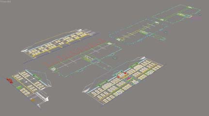
6. Execute the Zoom Extents All command. You should see the three floor plans and three elevations, as shown in the next illustration.
7. Save your file. If you wish to continue from this point with an already prepared scene, open the file ch03-01.max. Initiating a save early on is important so an automatic backup file can be generated from the start and used in the event of a computer or program crash.
8. Select all of the front elevation linework and create a group called Elevation-Front.
9. In the Hierarchy panel, click on Affect Pivot Only and use the Align command to align the pivot point of the group to the very bottom of the group; i.e., the blue ground line. You will need to make sure that the line you click on in the viewport to open the Align Selection dialog box is the actual line that represents the ground.
10. Close the Affect Pivot Only command.
11. Click on the Select and Rotate icon and then select the Use Pivot Point Center found on the Use Center flyout (2nd icon to the right of the Select and Rotate icon).
12. Rotate this group 90 degrees along the X-axis so it’s completely visible from the Front view.
13. Create a group called Elevation-Rear and Elevation-Side from the respective elevation linework.
14. Adjust the pivot points and rotate both of these groups the same way you did the first group, so you have all three elevations oriented, as shown in the next illustration.

15. If you wish to continue from this point with an already prepared scene, open the file ch03-02.max.
At this point, the scene is set and we are ready to begin modeling. Since the building is completely symmetrical, only one half of the building needs to be modeled and the other half can be a mirrored copy. Due to the limitations of printing such a complex and lengthy exercise as this, we will only model one of the walls in this building. However, the same procedure used to create the first wall can be used on all other walls.
The wall we are going to create is the main wall on the left side of the building. Although you could start by using the existing linework on the floor, it is always better to leave this linework as is for reference, and create your own new linework on top of the existing linework. This ensures that the linework used is properly constructed. Let’s start by creating a new line on top of the floor plan where the exterior surface of this block wall lies.
16. If you have not already done so, switch the Perspective view to an Orthographic view. This makes zooming in and out and panning around much easier.
17. Use the keyboard shortcut Alt+W to switch from a 4-viewport configuration to a single view-port configuration. This allows you to see your work better, and prevents 3ds Max from having to refresh 4 separate viewports.
18. From the Tools menu, select Grids and Snaps > Grid and Snap Setttings. Prior to 3ds Max 2009, this dialog box used to be found in the Customize menu.
19. Click the Clear All button to clear all previous snap modes.
20. Enable Endpoint mode and close the dialog box.
21. Enable 3D snaps (hotkey=S) and disable the home grid (hotkey=G).
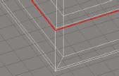
22. Zoom into the front left-hand side of the floor plan and create a line from the endpoint of the exterior side of the main wall seen on the left elevation, to the corner of the same main wall, to the end of the wall on the front of the building. The next illustration shows this line highlighted so you can see exactly where it needs to be created.
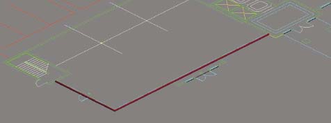
With this first line in place, we need to extrude it to the height of the wall we are modeling. First we need to measure the height of this wall.
23. Name this new line Bldg-MainWall. As a matter of good practice, I recommend labeling all building elements with some type of prefix, such as Bldg-. This keeps all the building objects listed together inside the various object display dialogs.
24. If you wish to continue from this point with an already prepared scene, open the file ch03-03.max.
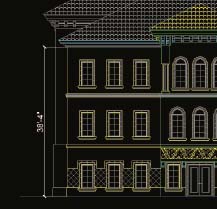
25. If you have AutoCAD, return to the file ch03-01.dwg and use the DIST command to measure the distance from the blue ground line to the top of the wall, as shown in the next illustration. If you do not have AutoCAD, use the tape-measure tool in 3ds Max to measure this same distance using the Elevation-Front group. The distance should be measured as 38’-4”.
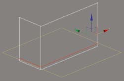
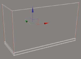
26. Return to the 3ds Max scene and use the Extrude modifier to extrude the 1st line you created 38’-4”. Note that if you created your line by clicking on the 3 endpoints in a counterclockwise manner, you should see an extruded line as shown in the following illustration. If you created your line in a clockwise direction, then the polygons of the extrusion will be facing toward the inside of the building, and you will have to flip the normals of this object.

27. Add the Shell modifier. This will allow us to apply thickness to the wall.
28. Within the Shell modifier, change the Outer Amount to 0.0, the Inner Amount to 8.0. Changing the Outer Amount to 0.0 ensures that the outer surface doesn’t move and changing the Inner Amount to 8.0 makes the wall 8 inches thick.
29. At the very bottom of the Shell modifier, enable the Straighten Corners option. This ensures that the shell remains 8 inches thick throughout the entire length of the spline.
30. Use the keyboard shortcut Alt+Q to isolate the wall object you are creating and the Elevation-Front group. This will allow you to see how the wall object you are creating matches the front elevation without the distraction of all the other linework.
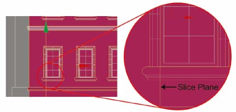
31. Switch to a Front view and enable Smooth + Highlights mode. Notice that the new wall matches the elevation. The first modification we are going to make to this wall is to add the trim feature along the bottom of the wall, as shown in the following image. This trim feature is not something that is ever depicted on a floor plan, which is why it sticks out beyond the new wall we created. To create this trim feature we must divide the existing polygons we have, and create new vertices at the top of the trim.

32. If you wish to continue from this point with an already prepared scene, open the file ch03-04.max.
33. Add the Edit Poly modifier to the Bldg-MainWall object.
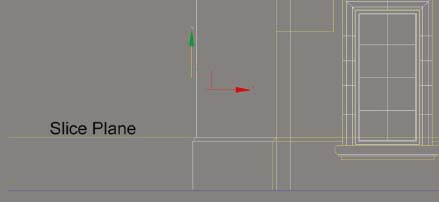
34. Open Edge sub-object mode and inside the Edit Geometry rollout click on the Slice Plane button. When you click this button a yellow slice plane is created at the home grid.
35. Use the transform gizmo to move the slice plane up to the top of the trim that runs along the bottom of the main wall we are trying to create. Zooming in very close will allow you to make this placement more accurate than you would ever need it to be, although you could refer to the AutoCAD drawings and take a distance measure to find out exactly where it needs to be placed. Toggle between Wireframe and Smooth + Highlights mode as necessary.
36. Switch to an Orthographic view and zoom into the Bldg-MainWall object so you can see exactly what is going on with the slice plane. Notice that it is creating temporary edges as a visual guide, as shown below.
37. Click the Slice button. If you move the transform gizmos up now you will see the new set of edges created when you clicked this button.
38. Click on the Slice Plane button again to turn off the slice plane. When you do, the new edges are shown.
39. Switch to Polygon sub-object mode, and using a Window selection, select the 2 polygons at opposite ends of the wall bottom.

40. Hold down the Ctrl key and select the 2 polygons that represent the front-bottom portion of this wall. With these 4 polygons selected, we can now extrude this trim feature.

41. Zoom in closely to the bottom corner of the front and side of this wall object.
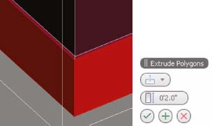
42. Inside the Edit Polygons rollout, click the Settings icon immediately to the right of the Extrude button. This opens the Extrude Polygons caddy. If you refer to the AutoCAD drawing or the imported Elevation-Front group, you would see that the trim needs to be extruded 2 inches.
43. Type 2 inside the Extrusion Height field and click Apply and Continue (the plus sign). The Apply and Continue button in all these features tends to be overly sensitive, and you should be careful not to enable the command more than once. Notice that the extrusion appears to occur in an undesirable direction. This is because with the Group option enabled as the Extrusion Type (first option in caddy), the extrusion takes place along the average normal of the group of polygons selected. To extrude these polygons properly, we need to extrude along the local normal of each polygon.
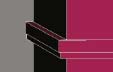
44. Select the Local Normal option as the Extrusion Type, and click OK (the checkmark) to close this command. The trim feature is now 2 inches thick along the length of both sides of the wall object, as shown in the next illustration.
Now that the trim is extruded, it needs to be tapered, as shown in the AutoCAD drawings. You could certainly go into vertex sub-object mode at this point, select the necessary vertices and move them down the required 2 inches. You could also take advantage of the Chamfer feature inside the Edit Poly modifier, which is what we will do now.
45. Enter Edge sub-object mode and select any of the top outer edges of the trim feature you just extruded.
46. In the Selection rollout, click the Loop button. This expands the number of edges selected as far as possible through four-way junctions, as shown in the next illustration. When the expansion reaches a three-point junction, as it does on the back side of these walls, no more edges will be selected. This is simply a quick way to select multiple edges.
47. In the Edit Edges rollout, click on the Settings icon immediately to the right of the Chamfer button. The Chamfer Edges caddy opens.
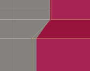
48. Type 2 in the Chamfer Amount field and click OK. The selected edges are now chamfered and the result is a tapered look to the top of the trim feature.

49. Switch to a Front view and zoom in closely to the top of the trim feature on the left side of the wall. As you can see in the next illustration, the tapered portion of the trim feature doesn’t match the original AutoCAD linework. The angle is much steeper than the 45-degree taper called for in the drawings. Why would this be?
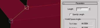
It’s because when the polygons were extruded, they were extruded 2 inches along the average normal, meaning that the corner vertices were pushed out 2 inches, as shown in the next illustration. The polygons, however, were only pushed out about 1.5 inches. In order for the polygons to have been pushed out 2 inches perpendicularly, we would have had to have used an extrusion value of about 2.8 inches. This demonstrates one of the many frustrating quirks of box modeling and one of the many limitations of using this technique. Knowing that a value of 2 inches wouldn’t suffice a veteran user would probably have switched to Front view in the first place and dragged up and down on the extrusion amount sliders until the extrusion matched the linework in the AutoCAD drawings. At this point, we have no choice but to fix this problem manually.
50. While still in Front view, enter Vertex sub-object mode, select the farthest left vertices that make up the trim, and move these vertices so they mimic the profile of the trim, as shown in the next illustration.

51. Unhide the Elevation-Side group, switch to Left view and repeat the previous step with the vertices making up the front of the wall object. When finished making the change, hide the side elevation again.
The next component of the wall that we’re going to craft is the double banding feature that runs along the top of the 1st floor, as shown in the next illustration. Just as before, we have to create additional edges within the structure, and this time we will use a different tool within the Edit Poly to do it.
52. If you wish to continue from this point with an already prepared scene, open the file ch03-05.max.
53. Switch to an Orthographic view, select the Bldg-MainWall object and enter Edge sub-object mode.
54. Select the 3 vertical edges on the outside surface of the wall object, as shown in the next illustration.
55. In the Edit Edges rollout, click on the Settings icon immediately to the right of the Connect button. The Connect Edges caddy opens.
56. Type 3 in the Segments field and click OK to end the command. The edges you had previously selected are now connected with 3 new edges running horizontally along the outside surface of the wall object, as shown in the next illustration. This is a quick and easy way to add edges to your object.

57. Switch to a Front view and reposition the 3 edges, so they are aligned vertically with the 3 lines that make up the banding feature we are trying to create. Switching back to Orthographic view makes it easy to select the 2 edges you need to move separately from the rest.
58. Refer to the AutoCAD drawing or the front elevation linework in 3ds Max and measure the depth of both parts of the banding feature. The distance should be measured at 3.25 and 4 inches.

59. Switch back to Orthographic view, and if you haven’t already done so, enable Smooth+Highlights and Edged Faces for this view. This will make it much easier to see the results of the next few steps.
60. Go to Polygon sub-object mode and carefully select the bottom 2 polygons that will form the bottom part of this banding feature.
61. Zoom in close to the corner of the banding feature, as shown in the next illustration.
62. Inside the Edit Polygons rollout, click on the Settings icon to the right of the Extrude button. The Extrude Polygon caddy opens. We will use this feature again but with a different option.
63. Select the By Polygon option and in the Extrusion Height field type 3.25, as shown in the next illustration. Click OK to close this command. This new option causes each polygon to be extruded along its respective normals, not as an average of a group of selected normals, or as if the vertices were being pushed out a specified amount. Because of this, the value entered in the Extrusion Height field will reflect the true extrusion amount. The problem, however, is that since the 2 polygons were extruded independently of each other, a section of the banding is now missing. To fill in this section, we can simply reposition the 4 vertices that make up this corner.

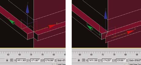
64. Switch to Vertex sub-object mode, and with the Move transform active, select the top left vertex, as shown in the next illustration. Notice that the X position of the vertex is displayed within the transform type-in field at the bottom of the screen. We need to apply this value to the X position of the vertices on the right-hand side to make them move to the proper location.
65. Copy the X value for this vertex, as shown in the left image, and paste this inside the X field value for the 2 vertices on the right-hand side. This causes these 2 vertices on the right to move to the same X position as the 1st vertex, as shown in the right image.
66. Use this same technique to reposition the 2 vertices on the left, so they occupy the same Y position as the 2 vertices you just moved.
67. Extrude the top portion of this banding feature using the same extrusion and vertex repositioning technique. The result should look like the next illustration.
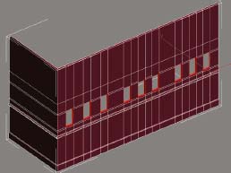
The many different trim features on this wall can be created in this same fashion as the 2 previous features, so at this point we won’t create any more. However, we haven’t yet created any windows and doors. Windows and doors both work the same way regardless of which method you choose to create, meaning that they can both be treated as the same type of object and should be created in the same way. For the purpose of this exercise, let’s create the 2nd floor windows on the front of the wall object we have been working on.
68. If you wish to continue from this point with an already prepared scene, open the file ch03-06.max.
69. Change to a Front view and zoom out to the extents of the Bldg-MainWall object. At this point we need to make edges for the windows we want to create. We will start with the vertical edges and then create the horizontal. The reason for creating the vertical edges before the horizontal ones will become apparent shortly.
70. Enter Edge sub-object mode and click on the Slice Plane button.
71. Rotate the slice plane 90 degrees about the Z-axis so it is vertical rather than horizontal.
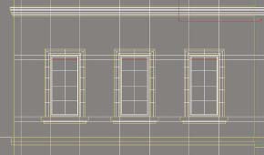
72. Move the slice plane so it’s at the left edge of the masonry opening of the farthest left window, as shown in the next illustration. The masonry opening is the same as the outer edge of the window frame, which is always the same as the opening indicated on a floor plan.
73. Click the Slice button to create the new edges.
74. Move the slice plane to the right side of the window and create a slice at the right side of the masonry opening of this window.
75. Repeat this for each of the remaining eight windows on the front of the Bldg-MainWall object. The result should look like the next illustration.
76. Rotate the slice plane 90 degrees about the Z-axis so it is horizontal once again. On the 2nd floor, there are 2 different window types at slightly different heights, and in the next few steps we need to create slices at the top and bottom of both types.
77. Create a slice at four different elevations, as shown in the next illustration. For the square shaped window, the slice needs to occur at the top and bottom of the masonry opening. However, on the window with the curved top we need to place the top slice at the top of the square frame, not at the top of the arch. The reason for this will be apparent in just a moment.
78. Create one final slice at the very bottom of the trim feature directly above the 2nd floor windows, as shown in the next illustration. We need to add this slice to separate the work we are going to do on the 2nd floor window from the windows on the 3rd floor. Had we already created this trim feature, this step would not be necessary.

79. Close the Slice Plane command.
80. If you wish to continue from this point with an already prepared scene, open the file ch03-07.max.
Because of the slice plane we created for the top of the windows with the arch, we have unnecessary edges running through the windows on both sides. These should be removed.
81. Select the edges running through the top part of the 3 windows on the left-hand side of the front elevation, as shown in the next illustration. Note: Since this needs to be done for both sides of the wall object, do not simply click on the edges. Use a Window selection to select the edges on the front and back of the wall at the same time.
82. Inside the Edit Edges rollout click the Remove button. This simply removes the unnecessary edges without deleting any polygons in the process. You cannot delete edges because doing so would also delete the polygons on both sides of the deleted edge.
83. Remove the additional edges running through the top of the 3 windows on the far right of the front elevation.
The 3 windows in the middle of the 2nd floor also have unnecessary edges running through their tops and bottoms. These will also have to be removed.
84. Remove the top-most edge running through the arched portion of these 3 windows, and the edge running through the bottom portion, as shown in the next illustration. Don’t forget to select these same edges on the back side of the wall object before removing.

85. If you wish to continue from this point with an already prepared scene, open the file ch03-08.max.
86. Switch to an Orthographic view and rotate your view to a perspective showing both the front and side of the wall object.
87. Switch to Polygon sub-object mode and select the 9 polygons that represent the 2nd floor windows you just created edges for, as shown in the left side of the next illustration.
88. Rotate the view to show the back side of the wall object and select the 9 polygons in the same location on the back side, as shown in the right side of the next illustration.

89. In the Edit Polygons rollout click on the Bridge button. The polygons you selected are deleted and new polygons are created for the sides of the new openings, as shown in the next illustration.
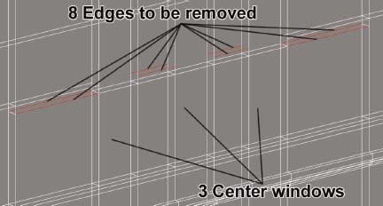
We’ve created 9 window openings on the 2nd floor of this wall object. We need to change the top portion of the 3 center windows to an arched window, but before we can do this we have to remove some extra edges we no longer need. Without removing the unnecessary edges around these 3 center windows, we cannot modify the windows as needed without extra polygons being left behind.
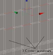
90. Switch to Edge sub-object mode and zoom into the 3 center windows.
91. If you have not already done so, switch to a Wireframe view.
92. Carefully select the 8 edges shown in the next illustration. These 8 edges serve no purpose because they are not part of the edges that make up the border of any window opening. Leaving them behind will cause problems with the next part of this exercise, which is turning these rectangular window openings into arched window openings at the top.
93. In the Edit Edges rollout, click the Remove button. These 8 edges are removed. Again, you cannot simply delete the edges by pressing the delete key on your keyboard, because doing so will delete any polygons connected to the deleted edges. Removing is more like optimizing.
Now we are going to add edges to the polygons immediately above the window openings, so we can curve the top portion of the openings to match the architectural drawings.
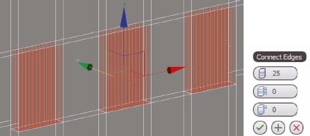
94. Select the 12 edges shown in the next illustration. These edges make up the top and bottom of the 2 outside and inside polygons directly above each of the 3 window openings.
95. In the Edit Edges rollout, click the Settings button immediately to the right of the Connect button. The Connect Edges caddy opens.
96. Type 25 inside the Segments field and click OK to end the command. This adds 25 additional edges to the area immediately above each window opening, as shown in the next illustration.
97. Switch to a Front view and zoom into the area above one of windows you just added edges.
98. If you wish to continue from this point with an already prepared scene, open the file ch03-09.max.
99. Using a Window selection mode (not Crossing), select all of the edges immediately above one (and only one) window opening, as shown in the next illustration.
100. While still in Edge sub-object mode, add the FFD(4x4x4) modifier. By being in Edge sub-object mode with certain edges already selected, you restrict the FFD modifier so it only affects the edges that are selected when the modifier is added.
101. Open the FFD(4x4x4) modifier and click on Control Points.
102. In Front view, create a window selection around the 2 rows of control points positioned in the middle and along the very bottom of the lattice, as shown in the next illustration.
103. Move the selected control points upward so the top of the newly formed arch aligns to the top of the arch defined in the architectural drawings, as shown on the left side of the next illustration.
104. With the same 2 rows of control points selected, perform a non-uniform scale along the X-axis so the 2 rows move away from each other, thereby making the model conform to the architectural drawings, as shown on the right side of the next illustration.

105. Repeat the last few steps to add curvature to the 2 remaining arched windows. To do this, you will have to add a new Edit Poly modifier and a new FFD (4x4x4) modifier to the 2 remaining arched windows. The result of modifying all 3 windows should look like the next set of images.

106. If you wish to continue from this point with an already prepared scene, open the file ch03-10.max.
The last thing we will do in this exercise is create the window frames for these 9 windows.
107. Switch to an Orthographic view.
108. Add an additional Edit Poly modifier to the modifier stack and switch to Polygon sub-object mode. When you do, the polygons that make up the inside of the window openings should be automatically selected because when you performed the bridge command earlier, those were the polygons that created the bridge and they remain selected until you deselect them. If you had inadvertently deselected them, you will have to reselect these same polygons.
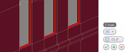
109. In the Edit Polygons rollout click the Settings icon to the immediate right of the Inset button.
110. In the Inset Polygons caddy enter 2.0 and click OK to complete the command. This creates new edges 2 inches from the outer edge of the windows, and means that our window frames will be 4 inches thick, as shown in the next illustration. If you want a different thickness to your frames, simply use the necessary inset amount at this time.
111. With these newly created polygons selected, click the icon to the right of the Extrude button.
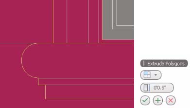
112. Select By Polygon, type 2 in the Extrusion Height field and click Apply, as shown in the next illustration. By clicking Apply, you can execute the extrusion (to see if it works properly) without closing the command and since the command is still active you can revert to a front view to determine exactly how far you need to extrude the polygons.
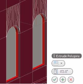
Close inspection of the window frames from Front view will indicate the extrusion should really be set to 0.5 inches, as shown in the next illustration.
At this point, you could complete all of the walls, windows, and doors for this building using the same features and procedures discussed so far. By continuing use of the Inset and Extrude features, you can quite easily form all of the window and door frames all at once, as well as the door and glass objects that lie within those frames. The exercise ends at this point, because continuing from here would only be repetition of the same steps already covered.
Summary
This chapter explained the many differences between the most commonly used methods of creating walls, windows, and doors. Through the use of a practical exercise, we focused specifically on how to create these objects using the box modeling method. In reality, the majority of the exercises in this chapter focused on creating walls and the window and door openings that lie within those walls. The actual door and windows that lie within those openings can be created with the box modeling method by just continuing with the same procedures and commands discussed.
While the box modeling method has a few inviting qualities about it, I would argue that it simply cannot compare to the speed and efficiency that can be achieved using the Loft command to create walls and the ProBoolean command to create window and door openings. At 3DAS, we do not endorse the box modeling method to create walls, windows, and doors on a large scale. However, the method was discussed at length because it is still a great solution for making modifications to existing objects, and all of the settings and procedures covered in this exercise will be applicable to countless other object types you need to create throughout the course of modeling a complete architectural scene. It was also discussed because many veteran users choose this method as the backbone for all their modeling. Furthermore, a complete understanding of all of the commonly used methods for doing a particular type of work in 3D is necessary, if you want to create an objective opinion about which method works best for you.
In the next chapter, we will look closely at how to create walls, windows, and doors using the Loft and ProBoolean features.