
Making a Scene
Playing Angry Bots was fun, but this book is about making games in Unity, not playing games in Unity! Finally, it’s time to get started in game development. It’s a long journey starting from nothing and ending up with a playable game, and this is the beginning. In this chapter, you’ll start with an empty scene in the Unity Editor and populate it with the basic building blocks of a 3D environment: models, textures, lights, a sky, and a camera.
One of the challenges facing a game developer, especially one on a limited budget, is how to obtain these building blocks. The Unity Editor provides some primitive models, and any image can be used as a texture (in the tradition of the Internet, I’ll provide you a picture of my cat as a sample texture). And, as mentioned in Chapter 1, the Unity installation includes a set of Standard Assets that can be imported into your project at any time. All of that can only take you so far, though.
Fortunately, the folks at Unity Technologies recognized this need and created the Asset Store, an online marketplace of Unity-ready assets with its storefront integrated directly into the Unity Editor. It turns out that a lot of these assets are free, so we’ll take advantage of that fact and incorporate some of these free assets into the Unity project created in this chapter.
Each chapter in this book (with the exception of Chapters 10 and 11 where the Angry Bots project stages a brief comeback) builds upon the project from the previous chapter. So by the end of this book, the simple static scene created in this chapter will have evolved into an optimized bowling game with sound and physics, running on iOS with leaderboards, achievements and ads. The project created in this chapter, along with the projects for each consecutive chapter, is available on http://learnunity4.com/ but minus any assets from the Asset Store or Standard Packages.
So without further ado, let’s get started!
Create a New Project
If you still have the Unity Editor running from the previous chapter, create a new Unity project using the New Project item in the File menu (Figure 3-1).
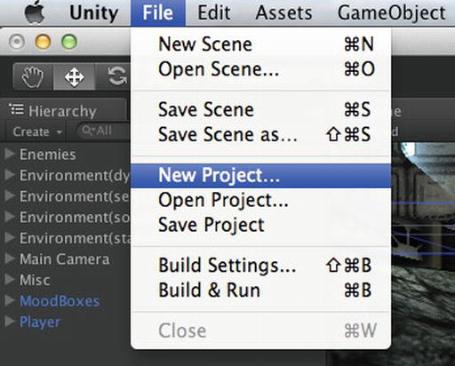
Figure 3-1. The New Project menu item
The resulting Project Wizard (Figure 3-2) is the same as the one we used when selecting Open Project in the previous chapter, but now it has the Create New Project tab selected. If you’re starting up a fresh Unity session and are presented with the Project Wizard, you can just click this tab to create a new project instead of opening an existing one.

Figure 3-2. Creating a new project with the Project Wizard
The Project Wizard prompts for the file name and location of the new project, defaulting to your home folder and the name New Unity Project (if the folder already exists, a number is appended, e.g., New Unity Project 1, or if that also exists then New Unity Project 2, and so forth). The Set button brings up a file chooser so you can browse for a directory location instead of typing it in.
You can name the project as you please or just use the default for now. The Unity project itself doesn’t care about its name, so you can rename the project folder in the Finder later (just make sure you exit Unity or switch to another project first, to avoid wreaking havoc with your current session).
Tip If you have a project that you want to keep around for a while, it’s a good idea to give it a meaningful name. More than once, I’ve discovered an old New Unity Project folder on my Mac and wondered if it was something important.
The Project Wizard presents a list of Unity packages that we can immediately import into our new project. These are the Standard Assets that were installed with Unity in the previous chapter. You don’t need to select any right now, as you can always import what you need later.
The Unity Editor will now appear, showing a new and empty project (Figure 3-3). The Project View displays no assets (you can confirm in the Finder that the Assets folder in your project contains no files), and the current scene is an untitled and unsaved scene consisting only of a GameObject named Main Camera.

Figure 3-3. How a new Unity project looks in the Editor
The first thing you should do is save and name this scene. The Save Scene option is found in the File menu (Figure 3-4) and has the same Command+S shortcut that is conventional with application save operations (you could think of scenes edited and managed by Unity as analogous to documents edited and managed by a word processing application).
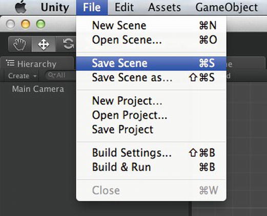
Figure 3-4. The Save Scene menu item
The resulting chooser will provide the project’s Assets folder as the default location, which is fine; the scene is an asset and part of the project, so the scene file has to go in the Assets folder. A default name is not provided, so you need to provide one. Let’s call it cube, since this scene will just showcase a cube. The new scene will show up in the Project View, with a Unity icon (Figure 3-5).

Figure 3-5. The new scene in the Project View
When you exit Unity or switch scenes or projects, Unity will prompt you to save the scene if there are unsaved changes (sometimes those changes are innocuous user interface changes, so don’t be alarmed). But it’s a good practice to save frequently, in case there’s a crash.
The File menu also has a Save Scene As command that is similar to the Save As command of other applications. It lets you save the scene under a new name at any time, effectively making a copy of the scene.
Tip Instead of using the Save Scene As command, it’s often simpler to select the scene file in the Project View and either rename (press Return) or duplicate (Command+D) the scene in the Project View.
You might be wondering about the difference between Save Scene and Save Project in the File menu. Save Project saves any changes to the project but not the current scene, while Save Scene also saves any changes in the current scene, i.e., changes to the GameObjects in the scene or changes to per-scene settings (Render Settings). Save Scene is what you’ll want to use most of the time. Save Project is appropriate when you’ve made some changes to project settings or assets that you want to save but have scene changes you’re not ready to save or maybe even have a new scene open that you don’t want to save at all.
The Main Camera
The Hierarchy View of the new scene lists just one GameObject, named Main Camera. Every new scene starts with that Camera GameObject, which acts as our eyes in the scene when we play the game. The Main Camera is special in that it’s easily accessible by scripts (it’s referenced by the variable Camera.main).
Multiple Cameras
The fact that the camera’s name is Main Camera might lead you to believe that multiple Cameras can exist in a scene, and you would be correct. It might seem strange to have multiple simultaneous viewpoints, but multiple Cameras make it possible to have a split-screen display or a window within the screen. Those usages aren’t actually supported in Unity for iOS (see the section “Viewport” below), but multiple Cameras are still useful for situations like rendering the game world with the Main Camera and rendering a user interface with another, effectively overlaying one set of GameObjects over another.
Anatomy of a Camera
Let’s select the Main Camera so we can see in the Inspector View what a Camera is made of (Figure 3-6).

Figure 3-6. Inspector View of the Main Camera
Starting from the top, you can see the name Main Camera. The check box to the left specifies whether this GameObject is active or inactive. If you uncheck the check box, the Camera is deactivated, indicated by a grayed-out appearance in the Hierarchy View, and you won’t see anything in the Game View. You can check the check box labeled Static on the right if you know this GameObject will never move. Marking GameObjects as static can facilitate optimization, although that rarely applies to Cameras.
Below the name, you can see this GameObject has MainCamera as its tag, which is really what designates this GameObject as a Main Camera. The name is just for display purposes, so you could edit the name here in the Inspector View without any repercussions.
The Layer menu for this GameObject is on the right. While names are used for description and tags for identification, layers are used to group GameObjects. You can think of these layers sort of like Photoshop layers. This Layer menu should not be confused with the Layers menu at the top right of the Editor window (they are unfortunately close to each other in the Default layout). The Layers menu at the top right controls which GameObjects are visible in the Scene View (it really should be located in the Scene View).
The Transform Component
Like every other GameObject, the Main Camera has a Transform Component that specifies the position, rotation, and scale of the GameObject. Scale is meaningless for Cameras, but the position and rotation allow you to place and point the Camera.
Click the little question mark icon on the top right of the Component. That will bring up the Reference Manual documentation for the Transform Component in a web browser window.
Tip Every time you encounter a new Component, the first thing you should do is check the documentation.
The Reference Manual page for each Component describes the properties of the Component and explains the usage of the Component. Each Reference Manual page also features a link to the corresponding Script Reference page for the Component, detailing how to access the Component from within a script.
The Camera Component
The Camera Component is what makes this GameObject a Camera. To be perfectly precise, Main Camera is a GameObject that has a Component which specifically is a subclass of Component called Camera. But it’s convenient to say Main Camera is a Camera (since that is its function), and say Camera Component to make clear that we’re talking about the Component.
Again, clicking on the question mark icon of this Component will bring up the corresponding Reference Manual page, listing the Camera Component properties. But I’ll go through them briefly here, in top-down order as they’re displayed in the Inspector View.
Clear Flags
The Clear Flags property specifies how the Camera initializes the color and depth buffers at the beginning of each rendering pass. The color buffer contains the pixels the Camera renders, and the depth buffer holds the distance from the Camera of each pixel (this is how it determines if a newly drawn pixel should replace the previous pixel at that location).
Solid Color indicates the color buffer will be cleared to the specified color, essentially using it as a background color, and the depth buffer will be cleared.
Skybox also clears the depth buffer and renders the specified Skybox textures in the background (defaulting to Solid Color if no Skybox is supplied).
Depth Only leaves the color buffer alone and only clears the depth buffer. This is useful when adding a Camera that renders after the Main Camera and over its results, e.g., to render a user interface or HUD (heads-up display) over the rendering of the game world. In that case, you don’t want the second Camera to clear the screen before rendering.
Culling Mask
This is where the usefulness of Layers becomes apparent. The Culling Mask specifies which Layers are rendered by the Camera. In other words, a GameObject will only be visible to the Camera if its Layer is included in the Camera’s Culling Mask.
The default, Everything, corresponds to all Layers, but, for example, if you had an HUD Camera, you might define an HUD Layer for all your HUD GameObjects and set the Culling Mask for the HUD Camera to only render the HUD Layer. And then you would set the Culling Mask of the Main Camera to include everything except the HUD Layer.
Projection
By default, the Camera is set to use a perspective projection, which as I mentioned in describing the Scene View in the previous chapter, means objects are smaller as they recede from the Camera (the effect is called foreshortening). In this mode, the Camera has a viewing volume resembling a four-sided pyramid (not counting the base of the pyramid) emanating from the Camera position in the view direction. This viewing volume is called a frustum and is defined by a Field of View (FOV), near and far plane.
The Field of View is analogous to the FOV of a real-world camera. The FOV is the vertical viewing angle, in degrees. The horizontal viewing angle is implicitly defined by the combination of the FOV and the aspect ratio of the Camera. The near and far planes specify how far the screen is in front of the Camera and how far away the base of the frustum is. Nothing outside the frustum is visible to the Camera.
To get a better idea of how the frustum looks, take a look at the Scene View. Figure 3-7 shows how the frustum of the Main Camera looks when you press the y-axis arrow on the Scene Gizmo, changing the vantage to a top-down view. Press the F key (shortcut for the Frame Selected command in the Edit menu) to center the Main Camera in the Scene View, then zoom out until you can see the entire frustum. You should also uncheck the 3D Gizmos check box in the Gizmos menu so that the Camera icon doesn’t shrink to nothingness when you zoom out.

Figure 3-7. The Camera frustum in the Scene View
The Scene View also displays a Camera Preview in the lower right corner. This is what the Camera would render right now, which is also what the Game View would display right now (you can take a look at the Game View right now to confirm). There’s nothing visible in this scene yet, but this will be a handy feature later.
Note that the frustum outline and the Camera Preview only display when the Camera is selected and the Camera Component in the Inspector View is open (every Component in the Inspector View can be opened or closed by clicking the little triangle in the upper left). This is generally true of any Component that has an extra graphic display in the Scene View. Opening and closing the Component in the Inspector View will toggle that display.
The alternative to perspective is orthographic, which has no foreshortening and thus is appropriate for 2D games, isometric games user interfaces, and HUDs. The only Camera property specific to orthographic mode is the orthographic projection size, which is the half-height of the orthographic view in world units.
Viewport
The Viewport of (0,0,1,1) indicates the Camera covers the whole screen. The numbers are normalized screen coordinates, meaning the coordinates across the width and height of the screen range from 0 to 1. For a split screen or a window within the screen, you would have multiple Cameras, each with different viewports, (0,0,1,.5) covers half of the screen. However, Unity iOS doesn’t support viewports that don’t cover the full screen.
Depth
Depth is another property useful when there are multiple Cameras in the scene. During each rendering update, the Cameras will perform their rendering passes in the order of their depth values, lowest to highest. So if you had a second Camera for viewing an HUD, for example, you might specify that the Main Camera has a depth of 0 and the HUD Camera a depth of 1 to ensure the game world renders first and the game HUD renders on top of that.
Rendering Path
The Rendering Path determines how the scene is rendered. Each Camera can have its own Rendering Path or default to the one specified in the Player Settings. Vertex Lit is the simplest but fastest path, Forward Rendering supports more advanced graphics, and Deferred is the fanciest but slowest and not available in Unity iOS.
Target Texture (Pro)
The render-to-texture feature is only available in Unity Pro and Unity iOS Pro. If a texture is assigned to this property, the Camera renders to that texture instead of the screen. The texture can then be placed in the scene, for example, as a television display or the rear-view mirror in a car.
FlareLayer Component
When a Camera GameObject is created from the GameObject menu, both a Camera Component and a FlareLayer Component are automatically attached. The FlareLayer Component allows the Camera to render Light Flares (described later in this chapter).
The FlayerLayer Component is a little unusual in that it’s not exposed to scripting, so it does have a Reference Manual page, but no Script Reference page. However, a FlareLayer Component can still be accessed from a GameObject using its class name, i.e., by calling GetComponent(“FlareLayer”).
GUILayer Component
A GUILayer Component is also automatically attached to a Camera GameObject. This component allows the Camera to render GUIText and GUITextures, which are 2D elements often used for user interfaces.
Note GUILayer, GUIText and GUITexture (and GUIElement, which is the parent class of GUIText and GUITexture) have nothing to do with UnityGUI, which is a newer built-in GUI system.
You may have noticed that the Inspector View displays GUILayer as one word and Flare Layer as two words. The Editor attempts to present class names in a more English-like fashion by introducing spaces in the names where an upper-case letter follows a lower-case one. That works fine for FlareLayer but not GUILayer. In any case, this book will stick to the original class name, since that is what will be referenced in scripts.
AudioListener Component
The AudioListener Component is only automatically attached to the Main Camera, since there can only be one active AudioListener at a time. Whereas the Camera Component is analogous to your eyes, responsible for rendering everything visible to it on your computer screen, the AudioListener Component is like your ears, responsible for routing all the audible AudioSources in the scene to the computer speakers.
Add a Cube to the Scene
You’ll already have noticed the Camera Preview and Game View display nothing, and the same happens in the Game View when you click the Play button. Of course, that’s because you don’t have anything in the scene besides the Camera. Let’s rectify that with the time-honored tradition of creating a cube.
Make the Cube
Under the Create Other submenu of the GameObject menu, Unity provides a number of GameObjects bundled with Components. Among these is a Camera GameObject, if we wanted to add another one. There is also a Cube GameObject along with a number of other primitive shapes (Figure 3-8).

Figure 3-8. Creating a Cube from the GameObject menu
Select the Cube item from the GameObject menu. That will create a Cube GameObject and add it to the current scene. The Cube will appear in the Hierarchy View (Figure 3-9) as the second GameObject of the scene.

Figure 3-9. A new cube GameObject in the Hierarchy View
Frame the Cube
Although the Cube is in the scene, it may not be immediately visible in the Scene View. To ensure the Cube can be seen in the Scene View, select the Cube in the Hierarchy View and press the F key (shortcut for the Frame Selected command in the Edit menu), which will center the Cube in the Scene View (Figure 3-10).

Figure 3-10. The Cube in the Scene View
Move the Cube
Remember, the Frame Selected command moves the Scene View camera, not the GameObject you’re looking at. The Cube may have been created at an arbitrary position, so set its position to the world origin, (0,0,0) in the Inspector View, by typing those coordinates into the x,y,z Position fields of the cube’s Transform (Figure 3-11). Don’t worry if you make a mistake.You can always Undo and Redo changes like this with the Undo and Redo commands in the Edit menu. In this case, you can Undo the Position change and then Redo it.

Figure 3-11. The Inspector View of a cube
Anatomy of a Cube
While you have the Cube displayed in the Inspector View, take a look at what it’s made of. Or, in other words, see what Components of the Cube make it a Cube.
Transform Component
Of course, as with every GameObject, there’s a Transform Component, which provides the position, rotation, and scale of the Cube.
MeshFilter Component
The MeshFilter Component references the 3D model, known in Unity as a Mesh,which consists of triangles and per-vertex information such as texture coordinates. When not referencing a built-in Mesh like the Cube, this property is assigned a Mesh from the project assets.
MeshRenderer Component
Hand-in-hand with the MeshFilter is the MeshRenderer Component, which determines how the mesh is rendered and is largely dictated by the Material (or list of Materials, if the Mesh is split into submeshes). You can think of a Material like the fabric on a sofa—the Mesh provides the shape and the Material wraps around the Mesh to provide the surface appearance.
The MeshRenderer also controls whether the Mesh receives shadows or casts shadows (I’ll introduce shadows later in this chapter).
BoxCollider Component
The MeshFilter and MeshRenderer Components together only make the Cube visible. The BoxCollider Component provides a physical surface that is used for collisions in the Unity physics system. Since there’s nothing that can collide with the Cube in this scene, you don’t need this Component. There’s no harm in leaving it there, but you could also disable the Component by unchecking its check box. Or you could remove the Component entirely from the GameObject by right-clicking it and selecting Remove Component from the resulting menu (Figure 3-12).

Figure 3-12. Removing a Component
Align With View
Since you moved the Cube, you can press the F key again to center it in the Scene View. But that doesn’t affect the Main Camera, as you can see from the Camera Preview in the Scene View and if you check the Game View.
Fortunately, there’s a convenient way to sync the Main Camera with the Scene View camera. Select the Main Camera, and then under the GameObject menu, invoke Align With View (Figure 3-13). Now the Main Camera has the same position and rotation as the Scene camera, and you can see in the Camera Preview that the Scene View and Game View are identical.

Figure 3-13. The Align With View command
Camera Control
Now if you click the Play button, you can see the Cube, but there’s not much going on. The Cube just sits there, and there is no interactivity. The first thing I like to do with a scene that has just one object like this is add a Camera orbit script so I can inspect the object from all angles. Conveniently, Unity comes with several Camera control scripts in the Standard Assets, including a MouseOrbit script.
Import the Script
To import that script, go to the Assets menu and select the Import Package submenu. This is the same list of Standard Assets packages presented when we created a new project (Figure 3-14).

Figure 3-14. Importing scripts from Standard Assets
From this list, selecting Scripts will present a window displaying all the scripts in the Scripts package (Figure 3-15). The scripts ending in the .js extension are written in JavaScript and the ones ending in the .cs extension are written in C#. You can import just the MouseOrbit script or all of the scripts. It’s easy enough to delete unwanted assets later.

Figure 3-15. The available Standard Assets scripts
Now the scripts and their containing folders are displayed in the Project View (Figure 3-16). The Project View doesn’t list the .js extension of the file names, but you can see from the icons that they are JavaScripts, and selecting a script will display the full name on the line at the bottom of the Project View.
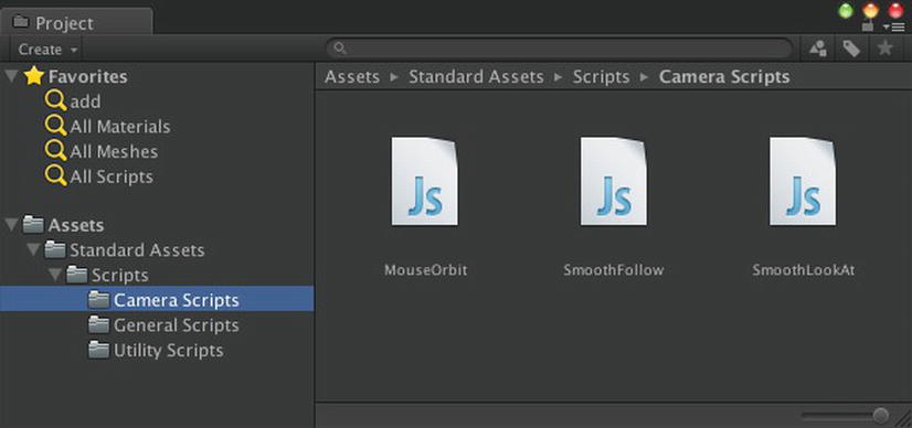
Figure 3-16. Standard Assets scripts in the Project View
If you select the MouseOrbit script in the Project View, the code in that script shows up in the Inspector View (Figure 3-17).
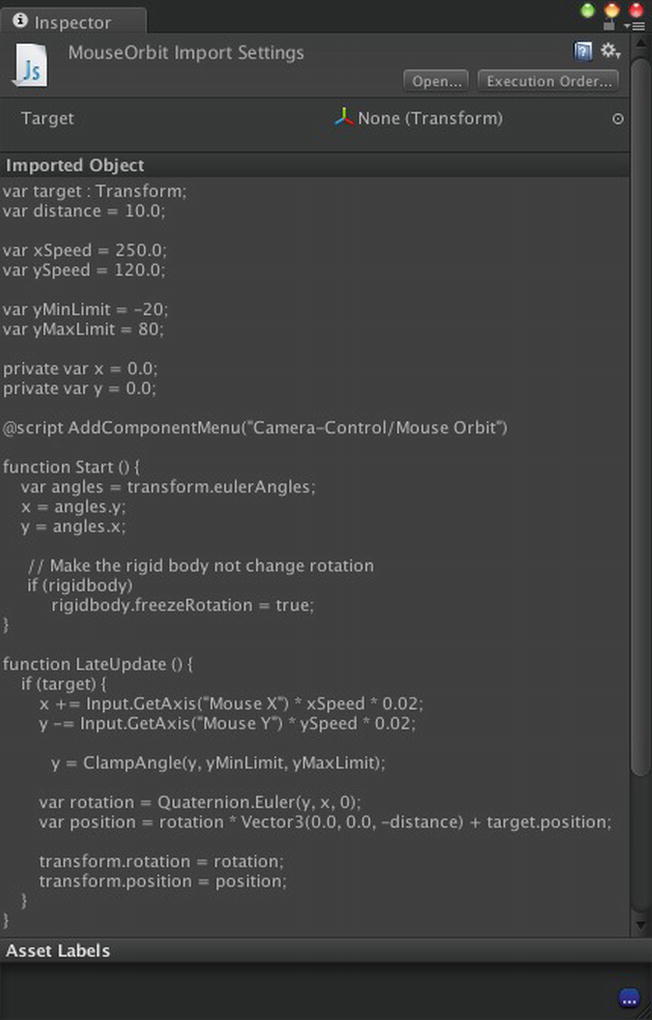
Figure 3-17. The Inspector View of the MouseOrbit script
Attach the Script
Drag the MouseOrbit script onto the Main Camera GameObject in the Hierarchy View. That attaches the script onto the GameObject, so now if you select the Main Camera, the MouseOrbit script will show up as one of its Components (Figure 3-18).

Figure 3-18. The MouseOrbit script attached to the Main Camera
The first property of the MouseOrbit Component is a reference to the MouseOrbit script (notice how Unity pretty-prints the Component type as Mouse Orbit, but don’t be fooled, it’s MouseOrbit!). You could actually change the script referenced by that property by dragging another one from the Project View into that field or by clicking the little circle on its right, which would pop up a list of available scripts to choose from (which right now are all the Standard Assets scripts you just imported).
The script itself determines the properties that follow. Notice that each of those properties in the MouseOrbit Component corresponds to a public variable declared at the top of the MouseOrbit script (each line beginning with var is a public variable, while those starting with private var are private).
Tip Selecting the Debug option in the Inspector View menu (top right corner) will display private variables as properties, too, which can be useful for debugging. Try it now and you’ll see the private variables x and y show up. The Debug option also adds diagnostic properties of built-in Components.
The first property defined by the script is Target, which is the GameObject the Camera will orbit around. It defaults to nothing (or in the code, null), so if you click Play, there is nothing for the Camera to orbit around. To rectify that, drag the Cube from the Hierarchy View into the Target field (Figure 3-19).
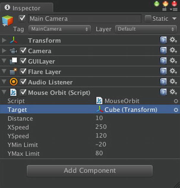
Figure 3-19. Assigning the Target property of the MouseOrbit script
Now when you click the Play button, the Camera orbits the Cube as you move the mouse. While in Play mode, you can adjust the other properties until you find values you like. The Distance property is the distance maintained between the Camera and the Target. Changing it to 3 brings the Camera close enough to the Cube so it fills up the Game View (Figure 3-20). The XSpeed and YSpeed properties control how much the Camera orbits in relation to the mouse movement, and the YMin Limit and YMax Limit properties set the angle limits of the Camera’s up and down rotation.

Figure 3-20. Testing the MouseOrbit script
When you exit Play mode, the properties revert to the values they had before you entered Play mode. At that point it’s necessary to enter the desired values again. If you end up with property values that you don’t like, you can always start over by clicking the icon on the top right of the Component and selecting Reset to revert back to the default property values.
Add a Light
You’ve probably been thinking the Cube looks awfully dark. Well, let’s add a Light! Under the Create Other submenu of the GameObject menu, several types of Lights are listed (Figure 3-21). Let’s choose Point Light.

Figure 3-21. Creating a Point Light
The Point Light now appears in the Hierarchy View and the Scene View (Figure 3-22), and you can see that its distinguishing component is a Light Component, with its Type set to Point. A Point Light only lights objects within its radius. So you should adjust its position or radius so that the cube will be lit. Here you can set its position to 5,5,5 (remember, the cube is at 0,0,0) and set the radius to 10.

Figure 3-22. The Inspector View of a Point Light
In the same way that a GameObject becomes a Camera when it has a Camera Component attached, a GameObject behaves as a Light when it has a Light Component attached. Like the Camera Component, the Light Component has several properties, which we’ll go over here in top-down order as shown in the Inspector View.
Type
The Type of a Light specifies whether it is a Point Light, Directional Light, Spot Light, or Area Light. Since this GameObject was created as a Point Light, it’s Type was automatically set to Point. In contrast to a Directional Light, which acts as a light source infinitely far away (it’s sometimes called an infinite light), a Point Light has a position (and is thus often known as a positional light) and radiates in every direction. A Spot Light also has a position, but radiates in a certain direction, like a cone. An Area Light is only used in generating light maps (lighting that is precalculated and “baked” into textures).
Range
The Range property for Point Lights specifies the radius of the Light. Only objects within the radius are affected by the Light.
Color
The Color property is the color emitted by the Light. Clicking the little color rectangle brings up a color chooser to assign this property.
Shadow Type
The Shadow Type property of a Light specifies whether it the Light projects shadows, and if so, whether they are Hard Shadows or Soft Shadows. Shadows are only available in Unity Pro and Unity iOS Pro and even then only for.Directional and Point Lights (in Unity iOS Pro, only Directional Lights).
Cookie
Directional and Spot Lights can project a cookie texture onto a surface, typicall to simulate a shadow.
Culling Mask
The Culling Mask property specifies the layers that the Light will affect. Very much like how the Culling Mask of the Camera Component dictates what objects are visible to the Camera, the Culling Mask of the Light dictates what objects are lit by a Light.
Flare
The Flare property, when assigned a Flare asset, produces a lens flare effect emanating from thsi Light.
Draw Halo
The Draw Halo property produces a halo effect around the position of the Light. When this property is enabled, an additional property for the halo color is made available.
Render Mode
The Render Mode of a Light specifies whether the Light is Important, Not Important, or Auto, which means its importance is determined automatically, based on the Light’s brightness and the current Quality Settings. A Light’s importance determines whether it is applied as a pixel light or not. Pixel lights are required for effects like shadows and cookies.
Adjust the Light
As with Cameras, when you have the Point Light selected and its Light Component open in the Inspector, more information about the Light is depicted in the Scene View. For a Point Light, the radius is displayed, so you can see what objects are affected by the Light (Figure 3-23). In order for the Cube to be affected by the Point Light, it must be within the Light’s radius. But remember, a Point Light radiates outward from its position, so you can’t have the Point Light at the same position as the Cube, because then the Light would be radiating from within the Cube and wouldn’t illuminate the Cube’s outer surface.

Figure 3-23. The Scene View of a Point Light
You can adjust the Light properties solely in the Inspector View, but try using the Scene View. Click the Move button in the button bar on the top left of the Editor (it’s the button with arrows directly right of the Hand tool). Now with the Point Light selected, the Scene View displays arrows centered at the Light that correspond to the x, y, and z axes of the Light. Click-dragging on any of those arrows will move the Light along the corresponding axis.
The circles around the Light delineate the range of the Light. You can adjust the range by click-dragging the little yellow rectangles just inside the circles. Anything within the range is lit by the Light, and anything outside the range won’t be affected by the Light.
Warning An object in exactly the same position as a Point Light won’t be affected by that Light.
Go ahead and move the Light and adjust its radius as necessary to make sure the Cube is lit. Now when you click the Play button, the Cube is lit, and the lighting varies as you orbit the Camera around the Cube.
Make a Halo
Right now the Point Light itself is invisible when you’re in Play mode. The Light’s presence is only evident through the GameObjects that it illuminates. However, you can see where the Light is coming from if you enable its halo. Enable the Draw Halo property in the Inspector View, and while you’re at it, click the Color property to change the Light’s color (Figure 3-24).

Figure 3-24. Selecting a halo color
This affects not only the color of the Light that is reflected off objects, but it’s also the color used to draw the halo. You can see the halo in the Scene View (Figure 3-25) and when you click Play (Figure 3-26).

Figure 3-25. The Scene View of a Point Light with a halo

Figure 3-26. The Game View of a Point Light with a halo
Add a Skybox
The Cube is looking more interesting, but the background is still blank, so let’s liven it up a bit by adding a sky. Specifically, you can add a skybox, which is a sky depicted by six textures comprising the six faces of the inside of a cube that surrounds it.
Import the Skybox
You can import Skyboxes from the Standard Assets just like you did for the Camera scripts. Under the Import Package submenu of the Assets menu, select Skyboxes (Figure 3-27).
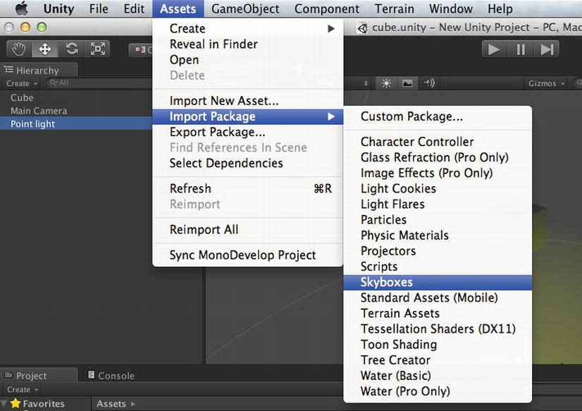
Figure 3-27. Importing Skyboxes from the Standard Assets menu
The resulting Import window (Figure 3-28) lists a whole bunch of Skyboxes. The .mat extension of the filenames indicates that Skyboxes are actually a kind of material, which is an object that describes how a surface is rendered. Skyboxes are sort of special-case Materials since they’re not applied to Meshes, just used for rendering the sky.

Figure 3-28. Skyboxes in Standard Assets
Go ahead and click the Import button. The Skyboxes and their supporting textures will appear in the Project View (Figure 3-29).

Figure 3-29. The Project View of Skyboxes
Anatomy of a Skybox
To get a better idea of the a Skybox’s composition, select the Sunny3 Skybox and examine it in the Inspector View (Figure 3-30). Since it’s a Material, the Skybox has a shader, which is a program instructing the graphics hardware how a polygon should be rendered, along with some parameters for the shader. Usually (but not always), the parameters for a shader include one or more textures. In the Inspector View, you can see the Skybox uses a RenderFX/Skybox shader, six textures for the Skybox sides, and a color that tints those textures.

Figure 3-30. The Inspector View of a Skybox
Apply the Skybox
To apply the Skybox to the scene, first make sure you have the Clear Flags property of the Main Camera set to Skybox. Then bring up the Edit menu and select Render Settings (Figure 3-31).

Figure 3-31. Selecting the Render Settings
The Render Settings are rendering properties that apply to the whole scene, including Fog, Ambient Light, and the Skybox (Figure 3-32).
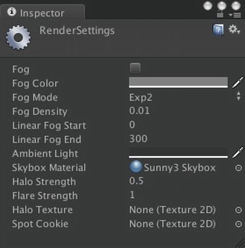
Figure 3-32. The Render Settings
Tip If you use fog, it’s a good idea to make the fog color match the tint color of the Skybox.
Note that the Render Settings you see apply only to the currently open scene. If you have multiple scenes in your project, each has its own Render Settings (otherwise you’re stuck with the same Skybox in each scene).
Drag the Sunny3 Skybox into the Skybox Material field, and you should see those blue skies and fluffy white clouds in the background of the Scene View and Game View (if you get tired of blue skies, try changing the Tint Color on the Skybox).
Another way to incorporate a Skybox into a scene is to add a Skybox Component to the Main Camera and assign the Skybox Material to that Component. That Skybox would override any Skybox assigned in the Render Settings. The only reason to use a Skybox Component is if you have multiple Cameras that have different Skyboxes.
Add a Flare
There’s an obvious analogy between Unity Cameras and, well, real cameras. That analogy can be stretched with the addition of Flares, which simulate lens flares, which are actually technical imperfections in camera lenses but used as effects by filmmakers (you may have seen quite a few, for example, in Firefly and J. J. Abrams’s Star Trek).
Import Flares
As with Skyboxes, Unity provides some built-in Flares in Standard Assets. Go to the Assets menu under Import Package submenu and choose Light Flares (Figure 3-33).

Figure 3-33. The Assets menu item for importing Flares
The package import window (Figure 3-34) reveals each Flare file has a .flare extension and contains a flare Material and a texture (notice that Unity conveniently supports .psd files for textures).

Figure 3-34. Flares in Standard Assets
Once the package is imported, the Flares show up in the Project View, represented by icons that resemble lens flares (Figure 3-35).

Figure 3-35. The Project View of Flares from Standard Assets
Apply the Flare
Let’s use the 50-mm Zoom Flare (that happens to be one of my favorites as it stretches farther along the Flare direction than the others). Drag that Flare into the Point Light’s Flare field (Figure 3-36).
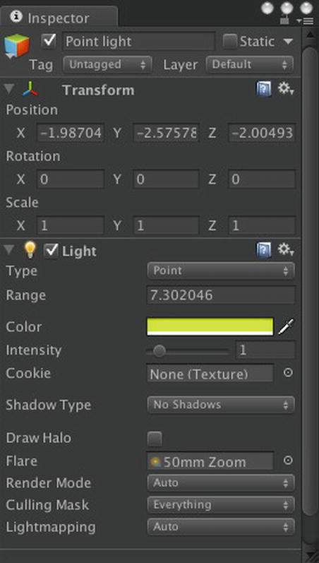
Figure 3-36. The Point Light with a Flare assigned
Now you can see the Flare in the Scene View emanating from the same position as the Point Light, and it looks even better when you click Play and orbit the Camera around the Cube (Figure 3-37). It’s a very cool effect!

Figure 3-37. The Game View with a Flare
A more flexible way to incorporate a Flare into the scene is to create a GameObject with a LensFlare Component and assign a Flare to that Component. This method allows placement and alignment of a Flare independent of any Light and provides additional brightness and color adjustment of the Flare.
Textures
Our scene is beginning to look pretty good, now that we have a Skybox and a Light with a halo and Flare, but the Cube still looks drab. It’s really the only thing left that doesn’t have a texture, but that is easily fixed!
Import a Texture
Just about any image file (.jpeg, .png, .tiff, .psd) on your Mac can be imported as a texture by invoking the Import Asset command in the Assets menu (Figure 3-38) and selecting the image file in the resulting chooser.

Figure 3-38. Importing a new asset
For this example, I’ve chosen a cat picture from my Photos directory, where it was stored by iPhoto. Feel free to use this file by downloading it from http://learnunity4.com/ (it’s in this chapter’s project, under the Textures folder). But if you have any image on your Mac in one of the supported file formats, that will be fine. After importing the image file, the resulting texture will appear in the Project View (Figure 3-39).
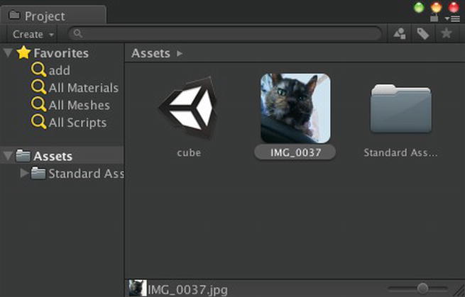
Figure 3-39. The Project View of a newly imported texture
Select the texture and examine its Import Settings in the Inspector View (Figure 3-40). The default Texture Type, Texture, is the preset type that is generally suitable for textures applied to models. If there are unapplied Import Settings, the Apply button is enabled and should be clicked (or Unity will prompt you to when it tries to use the texture).

Figure 3-40. The Inspector View of an imported texture
Notice how the Preview panel at the bottom summarizes the imported size and format of the Texture. The original image file has not been changed in any way, so importing the file effectively creates a duplicate of the original that is appropriate for our target platform. You never have to worry about messing up the original asset. In fact, you can always start over by right-clicking it in the Project View and selecting Reimport.
Note We’ve been using the term texture generically and without capitalization. There actually is a Texture class, that is the parent class of all types of textures, but the actual class name of the texture asset created by importing an image file is Texture2D (the other subclasses of Texture include Texture3D, MovieTexture and RenderTexture).
To apply the texture to the Cube, drag the texture onto the Cube in the Hierarchy View. This automatically creates a Material using the texture and applies that Material to the Cube, replacing the previous Material that was there. (Figure 3-41).

Figure 3-41. A texture applied to the Cube
In the Project View, you can now see the newly created Material is placed in a Materials folder located by the texture. Now if you click Play again, the Cube looks cool! (Figure 3-42).

Figure 3-42. The Game View of the textured Cube
Shop the Asset Store
Unity doesn’t have a built-in texture library in Standard Assets (although there are many textures used in the various packages). However, the Unity Asset Store, a marketplace of Unity-ready assets, has several free texture packs. Conveniently, the Asset Store is integrated into the Unity Editor. Under the Window menu (Figure 3-43), select the Asset Store item.

Figure 3-43. Selecting the Asset Store from the Window menu
This will bring up the Asset Store window and display the Asset Store front page (Figure 3-44), which lists the latest releases (both paid and free), categories, and featured items.

Figure 3-44. The Unity Asset Store
Let’s look for some free textures. Click the Textures & Materials category in the upper-right section of the page, and then select Price in the Sort By section on the left (Figure 3-45).

Figure 3-45. Free textures on the Asset Store
There are plenty of good candidates here, but if you scroll down, you should be able find to my favorite free texture library, the Free ArtskillZ Texture Pack. Click it to see the full product page (Figure 3-46). It includes the product description, screenshots, list of the individual files, and reviews.

Figure 3-46. The Free ArtskillZ Texture Pack on the Asset Store
Import the Texture
Click the Import button, and you’ll see the same type of Import window that you saw when importing the built-in Unity assets. Go ahead and import everything.
Now you’ll find all those textures in your Project View, separated into three folders categorizing them by genre (Figure 3-47).

Figure 3-47. The Project View of the ArtskillZ Textures
The textures displayed with blue icons are normal maps and are listed as such in their Texture Type fields. A normal map gives the illusion of a nonflat surface (sometimes the term bump map is used, although it’s not technically exactly the same).
Apply the Texture
For starters, we’ll try the ScifiPanel01 Texture. Drag it to the Cube and Unity automatically creates a new Material named after the texture and applies that Material to the Cube. But we want to use the normal map that accompanies that texture, so use the Shader selector of the Material in the Inspector View to change the shader to Bumped Specular. This shader accepts a second texture labelled Normalmap and also has a slider to control the Shininess property (it should be noted that the slider moves left to approach 1 and right to approach 0). Drag the normal map texture, ScifiPanel01_n, into the Normalmap field (Figure 3-48).

Figure 3-48. Scifi Texture applied to the Cube
Click Play, and you’ll now see the textured Cube (Figure 3-49).

Figure 3-49. The Game View of the Cube with a specular bump map texture
You could have also searched for free textures using the search field in the Project View. We'll use that option in ensuing chapters as we make use of more Asset Store packages.
Explore Further
This chapter may have seemed like it covered a lot of material (no pun intended) just to create a simple static scene, but a lot of basic Unity concepts were explored along the way, particularly the relationship between Components and GameObjects. As a result, now you have a scene with a bump-mapped and textured Cube, illuminated by a Point Light that’s sporting a Flare, and surrounded by a Skybox. The scene was populated with assets imported from local files, the Unity Standard Assets, and the Unity Asset Store. And the scene isn’t completely static, due to the MouseOrbit script attached to the Main Camera. Scripting will play a dominant role in this book, starting with the next chapter as we move beyond a static scene.
Before moving on to that, take a break and go over the official Unity documentation on the features used so far, if only to get familiar with where to find this documentation for future reference.
Unity Manual
The Unity Basics section of the Unity Manual was mostly relevant to the previous chapter, describing the user interface, but that section does have a “Creating Scenes” page. More relevant is the “Building a Scene” section, which describes the relationship among GameObjects, Components, and scripts, how to use the Inspector View to edit Component properties, and how to navigate the Scene View and move GameObjects, all of which was covered in this chapter. Lights and Cameras are also explained. One feature listed in this section that won’t be used in this book is the Terrain Engine (it is available in Unity iOS but slow). Terrain is a significant and impressive Unity feature, though, so it’s worth a read.The “Asset Import and Creation” section describes the asset types used in this chapter: Meshes, Materials, textures and scripts. The process of importing assets and the Asset Store are also explained.
We haven’t arrived at a point where we have gameplay, but the “Creating Gameplay” section has a page on “Transforms,” which as we saw is fundamental to understand even just for placing static GameObjects.
Reference Manual
Getting more in depth than the Unity Manual, the Reference Manual describes each Component in detail, explaining its properties and documenting the use of the Component. The Reference Manual also documents the asset types and gives an explanation of GameObject.
As a rule, you should read the Reference Manual documentation for every Component and asset type you use. Remember, there is a Help icon on each Component in the Inspector View that will bring up the appropriate Reference Manual page when you click it. Like the Unity Manual, the Reference Manual is available not just from the Unity Help menu but als on the Unity web site under the Learn tab (which can be reached directly at http://docs.unity3d.com/).The “Settings Manager” section of the Reference Manual includes a page on the Render Settings, which is where the Skybox in this chapter was assigned.The “Transform Components” section lists just one Component, naturally, the Transform Component, which is attached to very GameObject.
The “Mesh Components” section is more interesting, as it describes both the MeshFilter and MeshRenderer Components necessary for any GameObject with Mesh, such as the Cube created in this chapter.The “Rendering Components” section is more bountiful, yet, featuring the Camera Component and its associated GUILayer Component and FlareLayer. The Light Component is also documented here.Although assets aren’t really Components, the Reference Manual has a section titled “Asset Components,” which lists the various asset classes. In this chapter, Flare, Material, Mesh and Texture2D were incorporated into the scene (remember that Skybox is really a Material).
The most fun reading is in the section titled “Built-In Shader Guide,” which describes in detail (and with pictures) all of the built-in shaders, ranging from the simple and fast to very fancy. The Cube in this chapter started out with the default Diffuse shader and was replaced with a deluxe Specular Bump Map shader. As mentioned in this chapter, a shader is really a program, so if you can’t find a built-in shader that suits your needs, you can write your own by following the examples and instructions in the “Shader Reference” section.
Asset Store
This chapter begins our book-long practice of using free assets from the Unity Asset Store. I recommend browsing the Asset Store regularly to check the latest releases. Besides the free textures, models, and scripts, there are plenty of reasonably priced packages that can save you a lot of time and work. The Asset Store can also be viewed with a regular web browser at http://assetstore.unity3d.com/ (but without the ability to purchase or download any assets).
Computer Graphics
Computer graphics is a huge and intricate area of study. This chapter worked with 3D models, textures, bump maps, light flares, skyboxes, and we’re just getting started. So it’s well worth reading up on basic (and advanced) computer graphics, such as the popular and comprehensive text Real-Time Rendering, by Tomas Akenine-Möller, Eric Haines, and Naty Hoffman. Mark Haigh-Hutchinson’s Real-Time Cameras is an entire book devoted to the subject of virtual Cameras and their control schemes.
I won’t be covering the process of creating assets that can be imported into Unity, but Luke Ahearn has two books that may be generally helpful: 3D Game Textures: Create Professional Game Art Using Photoshop and 3D Game Environments: Create Professional 3D Game Worlds. And you can tell from the title of Wes McDermott’s Creating 3D Game Art for the iPhone with Unity that it’s an appropriate complementary text for this book.