
Allen Hux, Intel Advanced Visual Computing (AVC)
Some graphics algorithms require data structure construction and traversal steps that do not map well to constrained graphics pipelines. Additionally, because of the dependencies between rendering and non-rendering passes, much (or all) of the compute power of the device may go idle between steps of a given algorithm. In this gem, we examine techniques for executing non-rendering algorithms concurrently with traditional rendering on programmable graphics hardware, such as Larrabee. Such programmable graphics devices enable fine-grained signaling and event graphs, allowing algorithmic stages to “overlap.” As a working model, we present an implementation of Irregular Z-Buffer (IZB) shadows—an algorithm requiring both standard rendering passes (for example, depth-only pre-pass) and parallelized data structure construction. Identification of rendering and non-rendering work that is not dependent reveals opportunities to remove the stalls that currently occur when switching between the two types of workloads. The APIs discussed in this article are examples and not necessarily representative of APIs provided with a particular product.
The simplest shadow mapping algorithm requires two passes. First, render the scene from the light view to get a light-view depth buffer (at one resolution). Second, render the scene from the eye view (at the same or different resolution). For each point, test the visibility of that point by projecting it into the light view and comparing its depth to the one found in the first pass. If the eye-view depth is greater, then something must be between the light and the point being tested, and therefore it must be in shadow. This algorithm fits entirely within conventional rendering pipelines [Williams78].
The problem with this approach is aliasing: The resolution of the light-view plane will never precisely match the sampling frequency when projecting from the eye view, resulting in visual artifacts. As described in the previous gem, an irregular Z-buffer stores precise eye-view positions in the light-view grid, enabling accurate shadow determination from the eye view [Johnson04, Johnson09, Galoppo10]. Shadow mapping with an irregular Z-buffer is a multi-step process involving three rendering passes interleaved with two non-rendering steps.
Render the scene from the eye view, depth only.
Transform the eye-view points to light view.
For each point, atomic increment the corresponding pixel in the light-view plane. (A bigger plane improves parallelism at the cost of memory.)
Parallel prefix sum the indices, resulting in a mapping from each eye-view receiver to a light-view pixel.
Scatter the light-view values into a light-view-friendly 1D structure. Indices into the 1D structure are stored in the light-view plane.
Render the scene from the light view. Instead of executing a traditional pixel shader, test the triangle bounds against the points in the data structure (referring to the indices from Step 2c). Points that are inside and behind the triangle are in shadow. Set a bit in the data structure marking this point as in shadow (occluded).
Create a standard shadow map by traversing the data structure and scattering out the occlusion value to a traditional 2D image. We call this the “deswizzle” step.
Render the scene from the eye view again, using the shadow map.
For our purposes, this serves as an example of an algorithm that has some rasterization steps intermingled with some algorithmic work one might normally implement in C++. The second step in particular can result in quite a bit of idle hardware, because it requires a dependency chain of parallel and serial workloads.
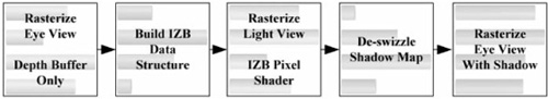
Assuming we have a graphics system capable of performing the compute steps of IZB (shown in Figure 1.7.1) and executing a pixel shader capable of traversing the IZB data structure, we get the simple dependency graph of tasks shown in Figure 1.7.2. Each stage in the graph cannot start until the last thread completes the last task of the prior stage.
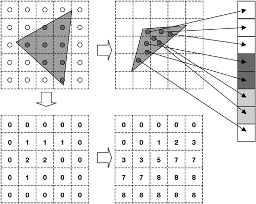
Figure 1.7.1. Building the IZB data structure, effectively a grid of lists. Regular points from the eye view (top left) are transformed into the light view (top middle). A count of the number of pixels is kept in the light grid (bottom left). A prefix sum of the counters in the light grid results in offsets (bottom right) into the 1D data structure (top right). Point data is scattered to the 1D data structure, including position and occlusion state (initially 0). The number of points in a light-view pixel can be determined by subtracting the current pixel value from the value to the right. The offset table combined with the 1D data structure forms the grid-of-lists IZB data structure.
Because there is almost always a “long pole” that determines the duration of a stage in the algorithm, nearly every thread in the system experiences some amount of idle time. This is suggested by the activity bars in Figure 1.7.2. (Imagine these correspond to the execution time on a system with four threads.) In the remainder of the gem, we will describe how we can reclaim some of those lost cycles on a programmable architecture, such as Larrabee.
As graphics devices become more general, they can be viewed as many-core compute devices with threads that can communicate amongst themselves (for example, via global variables and atomic instructions). Consider a representative programmable graphics architecture, Larrabee. Larrabee consists of many in-order cores on a single chip, each executing four threads in round-robin fashion, with an extended instruction set supporting 16-element vectors [Seiler08]. The cores are connected by a very high-bandwidth ring that maintains cache coherency. Several hardware texture samplers are distributed around the ring, as well as connections to GDDR. Traditional graphics APIs (DirectX, OpenGL) could be implemented on Larrabee as a typical process running within a relatively conventional operating system [Abrash09a].
A Larrabee architecture device could be an add-in adapter discrete from the traditional host CPU, it could be on-chip or on-die with the host CPU, or it could be the only processor in the system. For the purposes of this gem, we ignore the transport mechanism that enables our programs to run on the device, but it is important to realize that the techniques and code that follow are designed to execute directly on an architecture such as Larrabee.
Implementing an efficient rasterizer within a many-threaded, 16-wide SIMD platform is beyond the scope of this chapter, but we can summarize it here. Maximizing parallelism is the main design goal. (Keeping the cores busy will be a recurring theme.) The approach described by Abrash [Abrash09b] is to use a binning architecture where the bin dimensions are chosen such that the data accessed by each core (the depth buffer format and the pixel format) does not exceed the cache size of the core (256 KB L2, 32 KB L1 in the current Larrabee architecture). Done properly, operations such as depth tests would require no off-core bandwidth (neither ring nor GDDR accesses)—unless, of course, something wants to access that depth buffer later, which merely requires a one-time write at the end. Remember that textures are accessed via hardware texture samplers, which have their own caches. Despite the attention to bandwidth, the primary motivation for binning is to produce a lot of independent work that can be executed in parallel.
A programmable graphics device, such as a software rasterizer, would build a dependency graph of rendering tasks to complete (which we will call a render graph). We can expect rendering tasks to be roughly divided between front end (for example, vertex processing/binning) and back end (rasterization/pixel shading). A dependency graph enables independent tasks to run concurrently; for example, if a core completes pixel shading within a bin, it can work on a different bin or begin vertex shading for the next frame. Dependencies can be defined in terms of resources—for example, a render task may signal that it has completed writing to a render target resource (write dependency) or wait to start until a shadow map resource (texture) is ready for use (read dependency). The task affected (front end or back end) is a function of whether the resource is bound to the vertex shader or pixel shader.
Commands can be inserted within the graph to be executed when a resource is ready—for example, CopySubResource of a render target. We can also create nodes in the graph that are signaled by outside events, such as direct memory access (DMA) transfer completions. We will discuss dependency graphs in more detail in the subsequent sections.
Non-rendering algorithms hoping to effectively use many-core architectures require an efficient tasking system, such as Cilk [Blumofe95]. Such a task system leverages a thread pool (where the number of software threads is less than or equal to the number of hardware threads) to avoid operating system overhead from switching between threads. A good tasking system also provides the following features:
The ability to create individual tasks or sets of tasks (task sets). A task set calls the same task function a user-defined number of times (in parallel).
Tasks and task sets may depend upon each other. Specifically, a task or task set will not start until the tasks or task sets it depends on have completed.
Tasks and task sets may also depend upon user-defined events. Events can be signaled by simply calling a NotifyEvent API.
An efficient work-stealing scheduler to automatically spawn and load-balance among independent tasks.
Following is an example of what such a task API might look like. Tasks call a user function with user data. Task sets call a user function with user data and a number indicating which instance this is (0..numTasks-1).
// create an individual work item
typedef void (* const TaskFunction)
    (void* in_pTaskFunctionArg);
SyncObject CreateTask(
    TaskFunction in_pTaskFunc, void* in_pData,
    SyncObject* in_pDependencies,
    int in_numDependencies);

// create work items that do a subset of work
typedef void (* const TaskSetFunction)
    (void* in_pTaskSetFunctionArg,
    int in_taskIndex, int in_taskSetSize);
SyncObject CreateTaskSet(
    int in_numTasksInSet,
    TaskSetFunction in_pTaskFunc, void* in_pData,
    SyncObject* in_pDependencies,
    int in_numDependencies);

SyncObject CreateEvent(bool initialState);
Since the task system itself is software, common-sense performance heuristics apply: The amount of work done in the task should be sufficient to compensate for the overhead of the tasking system, which includes the function call into the task as well as some amount of communication to synchronize with internal task queues. For example, to perform an operation across a 1024×1024 image, don’t create one million tasks. Instead, create a multiple of the number of hardware threads in the system. For a system with 100 hardware threads, 400 or 500 equally sized tasks would give the task system some opportunity to greedily load balance, while each task of approximately 2,000 pixels would give good opportunities for prefetching and loop unrolling. (A Larrabee optimized routine would operate on 16 pixels at a time, hence a loop of only about 100 iterations.) Our experiments on desktop x86 machines show that tasks of a few thousand clocks each achieve 90 percent or better overall efficiency.
Efficient graphics processing requires thread affinity knowledge. That is, the rasterizer assigns threads to cores with the expectation that those threads will share render target data in their cache. Non-rendering tasks typically function more opportunistically, executing whenever a thread becomes idle. Hence, we design our tasks to be independent of the threads they may execute on. Since the hardware is programmable, finer control is possible but adds complexity.
Even with equal-sized tasks, in a machine with that many threads, contention for resources (caches and GDDR bandwidth) will cause tasks to have variable durations. For very irregular workloads, such as irregular Z-buffer, optimal performance may require thousands of tasks—it all depends on the algorithm.
The ability to create non-rendering task sets that depend on, or are dependencies of, rendering tasks is the key to achieving maximum hardware utilization for these mixed-usage algorithms. To do this, we need a way to interact with the rendering dependency graph from user code. Following is a method to inject a non-rendering task into the render graph, referring to the current render context (analogous to a DirectX or OpenGL context), a function to call when the dependencies are met, user data to pass to the function, and a list of all the resource dependencies.
void CreateRenderTask(in_pRenderContext,
    in_pUserFunc, in_pUserData,
    in_pReadDependencies, in_numReadDependencies,
    in_pWriteDependencies, in_numWriteDependencies,
    out_pRenderTask);
We then need a way to notify the render system that the render task and its read and write dependencies, as declared above, are complete and available.
void NotifyRenderTaskComplete(in_pRenderTask);Now we have a way for tasks created using our task system to define dependencies with rendering tasks and for rendering tasks to very finely interact with our task system. For example, if a render pass has pixel shaders bound to a resource declared as a write dependency of a user task, the front end of the render pass can start (transform/ bin), but the back end cannot (rasterize/pixel shade).
We need a little helper glue to efficiently communicate between “render” work and the tasks created for our “client” work. Following, we show how an event that waits on a task set can call NotifyRenderTaskComplete() to enable dependent render work. We also show how render work can cause a callback declared in CreateRenderTask() to signal an event, thereby starting dependent client work.
On the left side of Figure 1.7.3, we show how a render pass can be made to wait on client work. First, create a task set that does some client work, such as builds a data structure. Next, create a render task with the data structure (resource) written to by the task set as a write dependency, no read dependencies, and no callback. Then, create a render pass with the data structure resource as a read dependency. Finally, create a task that depends on the task set that will call NotifyRenderTaskComplete(). The render pass cannot start until the task set is complete.

On the right side of Figure 1.7.3, we show how client work can be made dependent on a render pass. First, create an event that we will signal and a task set that depends on the event. (It would do work on the render target.) Next, create the render pass, which in this case writes to a render target (write dependency). Finally, create a render task with the render target as a read dependency and a callback that will set the event. The task set cannot start until the render pass is complete.
To reduce the idle time, we need to build a complete dependency graph including both rendering and non-rendering tasks. Below, we work with the following constraints:
Tasks or task sets must have their dependencies described at creation time.
Tasks or tasks sets can depend on tasks, task sets, or events.
These constraints force us to work from the end of the algorithm backwards. Since a task will start immediately if it has no dependencies, we create events in a not-signaled state to act as gates for the task sets.
Create a build data structure event (not signaled).
Create a build data structure task set that depends on event (1).
Create a deswizzle event (not signaled).
Create a deswizzle task set that depends on event (3).
Create a light-view render pass where:
Rasterization depends on resource from task set (2).
Render target resource complete signals event (3).
Create a final eye-view render pass where rasterization depends on the shadow map resource from task set (4).
Create a depth-only eye-view render pass that signals event (1) when its render target resource is complete.
As soon as we complete the seventh step, creating the depth-only eye-view render with no dependencies, the whole algorithm will fall into place. As shown in Figure 1.7.4, when the depth-only pass (7) completes, it signals the build event (1), which enables the build task set (2) to start. Completion of the build task set (2) enables the light-view rasterization (5) to start. (Transform and binning should already be complete.) When the light-view render (5) completes, it signals the deswizzle event (3), which enables the deswizzle task set (4) to start. When the deswizzle task set (4) completes, it enables the final eye-view rasterization (6) to start. (Transform and binning should already be complete.)

Figure 1.7.5 shows the naïve linear dependency graph of the IZB algorithm discussed earlier, showing the render stages expanded into front end (transform + binning) and back end (rasterization + pixel shading) for a total of eight stages, or task sets.

Figure 1.7.6 shows how threads that would otherwise have become idle can instead work on non-dependent front-end rendering tasks if we start all three render passes immediately. This overlapped execution is especially helpful for improving the performance of our irregular shadow-mapping tasks, allowing us (in this example) to fully hide the cost of the front-end rendering tasks. Another way to interpret this is that the compute part of irregular shadow mapping is essentially free when overlapped with rendering.
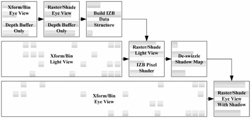
Figure 1.7.6. IZB with dependency graph integrated with flexible rendering pipeline. Xform/bin tasks can complete as threads become available from non-rendering tasks, filling in gaps in execution.
This demonstrates another advantage of programmable hardware: Maximum performance is achieved by enabling flexible hardware to execute whatever tasks are available, rather than by partitioning the hardware into dedicated islands of computation. Compare this to the early days of graphics devices with dedicated pixel shader and vertex shader hardware: When there was more vertex work than pixel work, the idle pixel shading hardware could not be reconfigured to help out. In modern architectures, graphics processors dynamically load balance across all execution units. On a programmable architecture such as Larrabee, this load balancing can be controlled by the programmer, enabling the overlap of rendering and non-rendering tasks.
Maximizing performance on modern, many-core platforms requires identifying independent work to be executed in parallel. Non-graphics workloads leverage a system of dependent tasks and task sets to manage parallel computation. On programmable graphics devices such as Larrabee, a similar system of task dependencies can be used to identify independent and dependent graphics work—for example, binning versus pixel shading. By connecting these graphs, we can further exploit available execution units by exposing more opportunities for independent tasks to run concurrently.