
Font rendering is an essential component of almost all interactive applications, and while techniques exist to allow for fully scalable vector-based font rendering using modern GPUs, the so-called “bitmap font” is still the most versatile, efficient, and easy-to-implement solution. When implemented on typical graphics APIs, however, this technique uses run-time updated vertex buffers to store per-glyph geometry, resulting in inefficient rendering performance by potentially stalling the graphics pipeline. By leveraging efficient particle system rendering techniques that were developed previously, it is possible to render thousands of glyphs in a single batch without ever touching the vertex buffer.
In this article, I propose a simple and efficient method to render fonts utilizing modern graphics hardware when compared to other similar methods. This technique is also useful in that it can be generalized for use in rendering other 2D elements, such as sprites and graphical user interface (GUI) elements.
The most common font format is the vector-based TrueType format. This format represents font glyphs (in other words, alphabetic characters and other symbols) as vector data, specifically, quadratic Bezier curves and line segments. As a result, TrueType fonts are compact, easy to author, and scale well with different display resolutions. The downside of a vector font, however, is that it is not straightforward to directly render this type of data on graphics hardware. There are, however, a few different ways to map the vector representation to a form that graphics hardware can render.
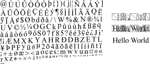
One way is to generate geometry directly from the vector curves, as shown in Figure 1.1.1. However, while modern GPUs are quite efficient at rendering large numbers of triangles, the number of polygons generated from converting a large number of complex vector curves to a triangle mesh could number in the tens of thousands. This increase in triangle throughput can greatly decrease application performance. Some optimizations to this way of rendering fonts have been introduced, such as the technique described by Loop and Blinn in which the polygonal mesh consists merely of the curve control points while the curve pixels are generated using a simple and efficient pixel shader [Loop05]. While this is a great improvement over the naive triangulation approach, the number of polygons generated in this approach is still prohibitively high on older graphics hardware (and that of the current console generation—the target of this article).
Because of these limitations, the most common approach relies on rasterizing vector graphics into a bitmap and displaying each glyph as a rectangle composed of two triangles (from here on referred to as a quad), as shown in Figure 1.1.2. A font texture page is generated with an additional UV offset table that maps glyphs to a location in that texture very similar to how a texture atlas is used [NVIDIA04]. The most obvious drawback is the resolution dependence caused by the font page being rasterized at a predefined resolution, which leads to distortion when rendering a font at a non-native resolution. Additional techniques exist to supplement this approach with higher quality results while mitigating the resolution dependence that leads to blurry and aliased textures, such as the approach described by [Green07]. Overall, the benefits of the raster approach outweigh the drawbacks, because rendering bitmap fonts is incredibly easy and efficient.
To draw glyphs for a bitmap font, the program must bind the texture page matching the intended glyph set and draw a quad for each glyph, taking into account spacing for kerning or other character-related offsets. While this technique yields very good performance, it can still be inefficient, as the buffers containing the geometry for each batch of glyphs must be continually updated. Constantly touching these buffers is a sure way to cause GPU stalls, resulting in decreased performance. For text- or GUI-heavy games, this can lead to an unacceptable overall performance hit.
One way to draw the glyphs for the GUI is to create a GUI model that maintains buffers on the graphics card for drawing a predefined maximum number of indexed triangles as quads. Whenever a new glyph is to be drawn, its quad is inserted into a list, and the vertex buffer for the model is eventually updated with the needed geometry at a convenient point in the graphics pipeline. When the time comes to render the GUI model, assuming the same texture page is used, only a single draw call is required. As previously mentioned, this buffer must be updated each frame and for each draw batch that must be drawn. Ideally, as few draw batches as possible are needed, as the font texture page should contain all the individual glyphs that would need to be rendered, but on occasion (such as for high-resolution fonts or Asian fonts with many glyphs), it’s not possible to fit them all on one page. In the situation where a font glyph must be rendered from a different page, the batch is broken and must be presented immediately so that a new one can be started with the new texture. This holds true for any unique rendering states that a glyph may hold, such as blending modes or custom shaders.
The slowest part of the process is when the per-glyph geometry must be uploaded to the graphics card. Placing the buffer memory as close to AGP memory as possible (using API hints) helps, but locking and unlocking vertex buffers can still be quite expensive. To alleviate the expense, it is possible to use a buffer that is marked to “discard” its existing buffer if the GPU is currently busy with it. By telling the API to discard the existing buffer, a new one is created, which can be written to immediately. Eventually, the old buffer is purged by the API under the covers. This use of lock-discard prevents the CPU from waiting on the GPU to finish consuming the buffer (for example, in the case where it was being rendered at the same time). You can specify this with the D3DLOCK_DISCARD flag in Direct3D or by passing a NULL pointer to glBufferDataARB and then calling glMapBufferARB(). Be aware that although this is quite an improvement, it is still not an ideal solution, as the entire buffer must be discarded. Essentially, this makes initiating a small update to the buffer impossible.
Another step in improving performance is reducing the amount of memory that needs to be sent to the video card. The vertex structure for sending a quad looks something like this and takes 28 bytes per vertex (and 112 bytes for each quad):
struct GPU_QUAD_VERTEX_POS_TC_COLOR
{
      D3DXVECTOR4 Position;
      D3DXVECTOR2 Texcoord;
      D3DCOLOR Color;
};
Since the bandwidth across the AGP bus to the video card is not infinite, it is important to be aware of how much memory is being pushed through it. One way to reduce the memory costs is to use an additional vertex stream to update only that information that has changed on a per-frame basis. Unfortunately, the three essential quad attributes (position, texture dimensions, and color) could be in a state of constant flux, so there is little frame-to-frame coherency we can exploit.
There is one very easy way to reduce at least some of the data that must be sent to the video card, however. Traditionally, each vertex represents a corner of a quad. This is not ideal, because this data is relatively static. That is, the size and position of a quad changes, but not the fact that it is a quad. Hicks describes a shader technique that allows for aligning a billboarded quad toward the screen by storing a rightFactor and upFactor for each corner of the billboard and projecting those vertices along the camera axes [Hicks03]. This technique is attractive, as it puts the computation of offsetting the vertices on the GPU and potentially limits the need for vertex buffer locks to update the quad positions.
By using a separate vertex stream that contains unique data, it is possible to represent the width and height of the quad corners as a 4D unsigned byte vector. (Technically, you could go as small as a Bool if that was supported on modern hardware.) In the vertex declaration, it is possible to map the position information to specific vertex semantics, which can then be accessed directly in the vertex shader. The vertex structure would look something like this:
struct GPU_QUAD_VERTEX
{
      BYTE OffsetXY[ 4 ];
};
Although this may seem like an improvement, it really isn’t, since the same amount of memory must be used to represent the quad attributes (more so since we’re supplying a 4-byte offset now). There is an easy way to supply this additional information without requiring the redundancy of all those additional vertices.
If you’re lucky enough to support a Shader Model 3 profile, you have hardware support for some form of geometry instancing. OpenGL 2.0 has support for instancing using pseudo-instancing [GLSL04] and the EXT_draw_instanced [EXT06] extension, which uses the glDrawArraysInstancedEXT and glDrawElementsInstancedEXT routines to render up to 1,024 instanced primitives that are referenced via an instance identifier in shader code.
As of DirectX 9, Direct3D also supports instancing, which can be utilized by creating a vertex buffer containing the instance geometry and an additional vertex buffer with the per-instance data. By using instancing, we’re able to completely eliminate our redundant quad vertices (and index buffer) at the cost of an additional but smaller buffer that holds only the per-instance data. This buffer is directly hooked up to the vertex shader via input semantics and can be easily accessed with almost no additional work to the previous method. While this solution sounds ideal, we have found that instancing actually comes with quite a bit of per-batch overhead and also requires quite a bit of instanced data to become a win. As a result, it should be noted that performance does not scale quite so well and in some situations can be as poor as that of the original buffer approach (or worse on certain hardware)! This is likely attributed to the fact that the graphics hardware must still point to this data in some way or another, and while space is saved, additional logic is required to compute the proper vertex strides.
Another way to achieve similar results with better performance is to perform shader instancing using constant arrays. By creating a constant array for each of the separate quad attributes (in other words, position/size, texture coordinate position/size, color), it is possible to represent all the necessary information without the need for a heavyweight vertex structure. See Figure 1.1.3.

Similar to indexed vertex blending (a.k.a. matrix palette skinning), an index is assigned for each group of four vertices required to render a quad, as shown in Figure 1.1.4. To get the value for the current vertex, all that is needed is to index into the constant array using this value. Because the number of constants available is usually below 256 on pre–Shader Model 4 hardware, this index can be packed directly as an additional element in the vertex offset vector (thus requiring no additional storage space). It’s also possible to use geometry instancing to just pass in the quad ID/index in order to bypass the need for a large buffer of four vertices per quad. However, as mentioned previously, we have found that instancing can be unreliable in practice.

This technique yields fantastic performance but has the downside of only allowing a certain number of constants, depending on your shader profile. The vertex structure is incredibly compact, weighing in at a mere 4 bytes (16 bytes per quad) with an additional channel still available for use:
struct GPU_QUAD_VERTEX
{
      BYTE OffsetXY_IndexZ[ 4 ];
};
Given the three quad attributes presented above and with a limit of 256 constants, up to 85 quads can be rendered per batch. Despite this limitation, performance can still be quite a bit better than the other approaches, especially as the number of state changes increases (driving up the number of batches and driving down the number of quads per batch).
I will now describe some small but important facets of font rendering, notably an efficient use of clip-space position and a cheap but effective sorting method. Also, in the sample code for this chapter on the book’s CD, I have provided source code for a texture atlasing solution that readers may find useful in their font rendering systems.
Fonts are typically drawn in a back-to-front fashion, relying on the painter’s algorithm to achieve correct occlusion. Although this is suitable for most applications, certain situations may require that quads be layered in a different sort order than that in which they were drawn. This is easily implemented by using the remaining available value in the vertex structure offset/index vector as a z value for the quad, allowing for up to 256 layers.
To save a few instructions and the constant space for the world-view-projection matrix (the clip matrix), it’s possible to specify the position directly in clip-space to forego having to transform the vertices from perspective to orthographic space, as illustrated in Figure 1.1.5. Clip-space positions range from –1 to 1 in the X and Y directions. To remap an absolute screen-space coordinate to clip space, we can just use the equation [cx = –1 + x * (2 / screen_width)], [cy = 1 – y * (2 / screen_height)], where x and y are the screen-space coordinates up to a max of screen_width and screen_height, respectively.

On the book’s CD, I have provided code for a simple virtual texture system that uses atlases to reduce batches. This system attempts to load an atlased version of a texture if possible and otherwise loads a texture directly from disk. There are some switches (documented in the code) that demonstrate how to turn this system on and off to demonstrate how important it can be toward reducing the number of batches and maintaining a high level of performance.
The techniques demonstrated in this chapter were tailored to work on current console technology, which is limited to Shader Model 3. In the future, I would like to extend these techniques to take advantage of new hardware features, such as Geometry Shaders and StreamOut, to further increase performance, image fidelity, and ease of use.
On the accompanying disc, you’ll find a Direct3D sample application that demonstrates each of the discussed techniques in a text- and GUI-rich presentation. Two scenes are presented: One displays a cityscape for a typical 2D tile-based game, and the other displays a Strange Attractor simulation. In addition, there is an option to go overboard with the text rendering. Feel free to play around with the code until you get a feel for the strengths and weaknesses of the different approaches.
The main shader file (Font.fx) contains the shaders of interest as well as some additional functionality (such as font anti-aliasing/filtering). Please note that certain aspects (such as quad expansion) were made for optimum efficiency and not necessarily readability. In general, most of the code was meant to be very accessible, and it will be helpful to periodically cross-reference the files GuiModel.cpp and Font.fx.
In this gem, I demonstrated a way to render font and GUI elements easily and efficiently by taking advantage of readily available hardware features, such as instancing, multiple stream support, and constant array indexing. As a takeaway item, you should be able to easily incorporate such a system into your technology base or improve an existing system with only minor changes.