8.3 Applications in Image/Video Coding
8.3.1 Image and Video Coding
Along with the rapid development of multimedia and internet techniques, digital media are widely applied, such as digital television, internet streaming video and DVD-video. Raw media signals hold enormous amounts of redundancy in the time domain or the spatial domain, which means unnecessarily high storage capacity. Therefore the original media signal is disadvantageous for storage and internet applications with limited bandwidth. That is, media content usually needs to be compressed/encoded into smaller memory capacity and lower bitrate on the premise of quality. Of course, the encoded signal should be decoded before viewing.
For the language with which an encoder and decoder communicate, many image and video coding standards are developed. The currently deployed image coding standards are JPEG and JPEG 2000, while the development of video coding standards has evolved through H.261, H.262/MPEG-2, H.263/MPEG-4 (part 2), and H.264/MPEG-4 (part 10). The main video encoding standards comply with the architecture of Figure 8.6.
Let us explain more on two of the standards: MPEG-2 and H.264. In the MPEG-2 system, compression is completed by motion prediction, two-dimensional discrete cosine transform (DCT) performed on blocks of pixels and entropy coding shown in Figure 8.6. The coding gain of H.264 over MPEG-2 is in the range of 30–50%. Rather than using floating point DCT in MPEG-2, H.264 adopts integer DCT which makes the coefficients perfectly invertible. Other improvements in technique include: quantized DCT coefficients coded by context-adaptive variable length coding (CAVLC), tree structured motion compensation and deblocking loop filtering.
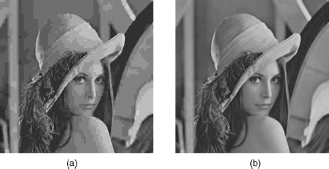
In the literature, some other methods have also been derived to cater for different situations and requirements in visual signal coding. For example, it is known that at low bit rates JPEG compression, a down-sampled image is applied, which visually beats the compressed high resolution image with the same number of bits, as illustrated in Figure 8.7, where (a) is by using JPEG compression and decompression, and (b) is down-sampling based, and the down-sampling factor is 0.5 for each direction. The compressed Lena images in both cases use 0.169 bpp (bit/per pixel). The reason for the better performance in Figure 8.7(b) over (a) lies in that high spatial correlation exists among neighbouring pixels in a natural image; in fact, most images are obtained via interpolation from sparse pixel data yielded by a single-sensor camera [45]; therefore, some of the pixels in an image may be omitted (i.e., the image is down-sampled) before compression and restored from the available data (e.g., interpolated by the neighbouring pixels) at the decoding end. In this way, the scarce bandwidth can be better utilized in very low bitrate situations.
Figure 8.7 An example of down-sampling based image coding (bpp = 0.169): (a) recovered image when coding without down-sampling; (b) recovered image when coding with down-sampling. With kind permission from Springer Science+Business Media: Lecture Notes in Computer Science, ‘Perception Based Down Sampling for Low Bit Rate Image Coding,’ 5879, © 2009, 212–221, Anmin Liu and Weisi Lin

Basically, in a sampling based coding method, a down-sampling filter (e.g., 2 × 2 average operator [46]) can be applied to reduce the resolution of the content to be coded. The encoded bit-stream is stored or transmitted over the bandwidth constrained network. At the decoder side, the bit-stream is decoded and up-sampled to the original resolution. Alternatively, the full-resolution DCT coefficients can be estimated from the available DCT coefficients resulting from the down-sampled sub-image, without the need of a spatial interpolation stage in the decoder [47].
8.3.2 Attention-modulated JND based Coding
For an image or a video frame, different areas have different visibility thresholds due to the visual attention mechanism and the JND characteristic of the HVS. Therefore, different blocks (note that most coding schemes are block based) could be represented with different fidelity. Let us consider the distortion measure for each block given by [16]:
(8.31) ![]()
where ![]() denotes the distortion weight and
denotes the distortion weight and ![]() is a constant. The distortion weight indicates that the block can tolerate more or less distortion. Therefore, for a block with higher distortion weight, a smaller quantization step size should be chosen to reduce the corresponding distortion. In [16], the distortion weight is defined as a noticeable perceptual distortion weight based on the visibility thresholds given by the attention-modulated JND model. The block quantizer parameter is adjusted as follows. Let Qr denote the reference quantizer determined by the frame-level rate control [48, 49]. The quantizer parameter for the block of index i is defined as
is a constant. The distortion weight indicates that the block can tolerate more or less distortion. Therefore, for a block with higher distortion weight, a smaller quantization step size should be chosen to reduce the corresponding distortion. In [16], the distortion weight is defined as a noticeable perceptual distortion weight based on the visibility thresholds given by the attention-modulated JND model. The block quantizer parameter is adjusted as follows. Let Qr denote the reference quantizer determined by the frame-level rate control [48, 49]. The quantizer parameter for the block of index i is defined as
(8.32) ![]()
where ![]() is defined as a sigmoid function to provide continuous output of the attention-modulated JND value as
is defined as a sigmoid function to provide continuous output of the attention-modulated JND value as
with a′ = 0.7, b′ = 0.6, m′ = 0, n′ = 1, c′ = 4 defined empirically. The quantity ![]() is the average
is the average ![]() of block i, and
of block i, and ![]() is the average
is the average ![]() of the frame. The noticeable distortion weight
of the frame. The noticeable distortion weight ![]() is obtained from the
is obtained from the ![]() information of the block, by Equation 8.33. A larger weight
information of the block, by Equation 8.33. A larger weight ![]() indicates that the block is more sensitive to noise. Such a block may be perceived at higher visual acuity, for example projected on the fovea due to attention, or cannot tolerate higher distortion due to low-luminance contrast or masking effects. So a smaller quantization parameter should be used to preserve higher fidelity. When the distance between the block and the fixation point is large, that means the eccentricity is larger, or the block is less sensitive to noise due to luminance contrast or masking effects, a smaller weight
indicates that the block is more sensitive to noise. Such a block may be perceived at higher visual acuity, for example projected on the fovea due to attention, or cannot tolerate higher distortion due to low-luminance contrast or masking effects. So a smaller quantization parameter should be used to preserve higher fidelity. When the distance between the block and the fixation point is large, that means the eccentricity is larger, or the block is less sensitive to noise due to luminance contrast or masking effects, a smaller weight ![]() will be obtained and a larger quantization parameter will be used.
will be obtained and a larger quantization parameter will be used.
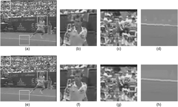
The gain brought by using visual attention information through attention-modulated JND map has been assessed using the H.264/AVC joint model (JM). Several regions of the reconstructed images are shown in Figure 8.8. Figure 8.8(b) shows a fixation (or attention) region of the reconstructed frame when coded/decoded with the JM-based algorithm. Its visual quality is worse than that coded with the method introduced in this subsection as shown in Figure 8.8(f). Since this region is the fixation region, it will be projected onto the fovea and perceived at higher resolution. Therefore, higher bitrate has been given in the attention-modulated JND map based method and the perceived quality is improved. Figure 8.8(c) shows a region away from the fixation region, which has been coded/decoded with the JM-based method. The attention-modulated JND model establishes that this region can accept higher distortion, since, first it is perceived at lower visual acuity due to its large distance from the fixation point, and second, it can accept higher distortion due to luminance contrast and masking effects. Lower bitrate has thus been allocated to this region but the distortion is imperceptible. Figure 8.8(g) shows the result obtained with the attention-modulated JND map based method. The attention-modulated JND model also indicates that although the region (Figure 8.8(h)) is not a fixation region, it should not be coarsely coded since distortion in smooth regions is easily perceived. Higher distortion in such a region is annoying and degrades the subjective quality, as shown in Figure 8.8(d).
Figure 8.8 Comparisons of regions of the reconstructed frame of the test sequence Stefan: (a) reconstructed frame from the JM-based method; (b) fixation region in (a); (c) texture region in (a) away from fixation points; (d) smooth region in (a) away from the fixation points; (e) reconstructed frame from the attention-modulated JND map based method; (f) fixation region in (e); (g) texture region in (e); (h) smooth region in (e) [16]. © 2010 IEEE. Reprinted, with permission, from Z. Chen, C. Guillemot, ‘Perceptually-Friendly H.264/AVC Video Coding Based on Foveated Just-Noticeable-Distortion Model’, IEEE Transactions on Circuits and Systems for Video Technology, June 2010

8.3.3 Visual Attention Map based Coding
In [47], an adaptive sampling method is proposed which adaptively decides the appropriate down-sampling mode (down-sampling ratio and direction(s)) and the quantization parameter (QP) for every macro block (MB) (an MB is 16 × 16 pixels, which is a composite of 2 × 2 blocks of 8 × 8 pixels) in an image, based upon the local visual content of the signal. However, the method in [47] is based on only the local visual content to decide the sampling mode and does not consider other characteristics of the HVS. Aiming at aligning better with the HVS perception to achieve better perceived quality for the compressed visual content, an improved scheme was proposed in [50] for determination of the down-sampling mode and the corresponding QP, with the consideration of visual attention mechanism.
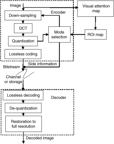
The block diagram of the scheme in [50] is shown in Figure 8.9, where the parts enclosed with dashed lines are the typical block diagram of a down-sampling based coding method (e.g., [47]) which has already been discussed in Section 8.3.1. In [47], the mode selection part is only affected by the quantization results while in Figure 8.9 this part is also controlled by the visual attention (or Region of Interest – ROI) map which can be used to improve the efficiency and effectiveness of the mode selection and the corresponding QP determination processes. The lossless coding procedure in Figure 8.9 is the entropy coding as shown in Figure 8.6.
Figure 8.9 Block diagram of the down-sampling based coding method (the parts enclosed with dash lines) and the inclusion of the visual attention mechanism [50]. With kind permission from Springer Science+Business Media: Lecture Notes in Computer Science, ‘Perception Based Down Sampling for Low Bit Rate Image Coding,’ 5879, © 2009, 212–221, Anmin Liu and Weisi Lin

The first 20% of the MBs with the highest attention values (given by computational models of visual attention in Chapters 3–5) are treated as the ROI and the other ones are deemed as non-ROI. Let ![]() denote the type of block. If a block belongs to the ROI, then
denote the type of block. If a block belongs to the ROI, then ![]() ; otherwise,
; otherwise, ![]() .
.
Four different down-sampling modes are used for a 16 × 16 block, with sampling ratios varying from 1/4 to 1, as listed in Table 8.3, where ![]() represents the ratio of number of pixels in an MB before sampling compared with that after sampling. With various down-sampling directions/ratios, the quantization step size can be reduced to code the DCT coefficients for the down-sampled pixels more accurately. For an MB, when no down sampling is performed and the initial QP value is performed is
represents the ratio of number of pixels in an MB before sampling compared with that after sampling. With various down-sampling directions/ratios, the quantization step size can be reduced to code the DCT coefficients for the down-sampled pixels more accurately. For an MB, when no down sampling is performed and the initial QP value is performed is ![]() , the corresponding bitrate is estimated as
, the corresponding bitrate is estimated as ![]() (bpp). For sampling mode
(bpp). For sampling mode ![]() , the allowed bitrate is
, the allowed bitrate is ![]() (where
(where ![]() is the required overhead bitrate, as to be discussed next), and the corresponding QP (
is the required overhead bitrate, as to be discussed next), and the corresponding QP (![]() ) can be estimated as
) can be estimated as
where ![]() and
and ![]() are the monotonically decreasing rate control function and its inverse function (e.g., determined as [49]), respectively; the actual QP (with the target bits associated with initial QP value of
are the monotonically decreasing rate control function and its inverse function (e.g., determined as [49]), respectively; the actual QP (with the target bits associated with initial QP value of ![]() ) should be around that which is estimated by Equation 8.34, and therefore, we have chosen the candidate QPs to be around
) should be around that which is estimated by Equation 8.34, and therefore, we have chosen the candidate QPs to be around ![]() . Aiming at adapting the QP to the visual content of a block, the candidate QP list is designed according to the type of the MB as shown in Table 8.3. A bigger
. Aiming at adapting the QP to the visual content of a block, the candidate QP list is designed according to the type of the MB as shown in Table 8.3. A bigger ![]() is assigned for a non-ROI MB and a smaller
is assigned for a non-ROI MB and a smaller ![]() is used for an ROI MB as in Equation 8.35:
is used for an ROI MB as in Equation 8.35:
(8.35b) ![]()
Table 8.3 Candidate coding models. With kind permission from Springer Science+Business Media: Lecture Notes in Computer Science, ‘Perception Based Down Sampling for Low Bit Rate Image Coding,’ 5879, © 2009, 212–221, Anmin Liu and Weisi Lin.
| Sampling mode | Candidate QPs | |
| one 16 × 16 MB to four 8 × 8 blocks (no down-sampling) | 1 | |
| one 16 × 16 MB to two 8 × 8 blocks (1/2 down-sampling in horizontal direction) | 2 | |
| one 16 × 16 MB to two 8 × 8 blocks (1/2 down-sampling in vertical direction) | 2 | |
| one 16 × 16 MB to one 8 × 8 blocks (1/2 down-sampling in both directions) | 4 |
As can be seen from Table 8.3, there are a total of 16 different combinations of the sampling modes and the corresponding QPs. So we need four more bits to represent the side information for each MB, and therefore, ![]() . Among these 16 different coding modes, only the modes with corresponding bitrate no larger than
. Among these 16 different coding modes, only the modes with corresponding bitrate no larger than ![]() can be used, and the one with the best reconstruction quality is finally selected for coding.
can be used, and the one with the best reconstruction quality is finally selected for coding.
The performance of visual attention map based coding is illustrated with Figure 8.10. This figure shows the amplified face and shoulder regions of image Lena (coded at 0.105 bpp), where coding schemes in both (a) and (b) are similar (i.e., sampling based coding), but visual attention mechanism is only considered in (b) through the method introduced above. The visual quality for (b) is better than that for (a), which means that image and video coding is a good application of visual attention.
Figure 8.10 Reconstructed images for the case where: (a) visual attention is not considered; and (b) visual attention is considered, at the same bitrate (0.105 bpp)


