8.5 Application in Compressive Sampling
In image and signal coding, an analogue signal or image is first transferred to digital data by sampling. The conventional approach of sampling signals or images follows Shannon's theorem: the sampling rate must be at least two times the maximum frequency (Nyquist frequency) present in the signal or image. For a high-resolution image with higher maximum frequency, the sampling data often includes huge numbers of pixels (billions or even trillions of pixels). The digital image has to be compressed by image coding for storage or transmission, and then the original digital image is recovered in the decoding stage. In the general image compression algorithm, as mentioned in Section 8.3, a digital image is first transformed into an appropriate basis space such as a discrete Fourier transform, a discrete cosine transform, a wavelet transform and so on, then only a few important coefficients in the transform domain are used to encode the information, and many other coefficients are discarded during this encoding process, so that the data of the image is compressed. In the decoding stage, the original digital image can be recovered based on a few important coefficients. In fact, much information obtained at the sampling stage is wasted in the process of image encoding and decoding. Is there a method that can find fewer data in the sampling stage? The original digital image can then be recovered from the obtained partial data.
A recent study has shown that the conventional Shannon/Nyquist sampling theorem perhaps may not hold. When certain conditions for an image are satisfied, it can be precisely recovered from much fewer sampling data or measurements than the Nyquist sampling rate; that is, these few important coefficients can be directly acquired at the sampling stage and the digital image can be recovered from the limited sampling data. A novel sampling theory called compressive sampling (CS), also referred to as compressed sensing, is proposed in [67–69]. CS theory mathematically proves that when a signal or an image has sparse representation and the measuring matrix is incoherent with the sparse representation, the signal or image may be recovered from limited sampling data [70–72]. CS can reduce the unnecessary burden on the digital signal or image acquisition process. The signal recovery algorithms from the limited sampling data mainly use linear programming [73], orthonormal matching pursuit [74, 75], gradient projection sparse reconstruction [76] and so on. CS theory is a potentially powerful tool to reduce the number of acquired samples and still reconstruct the digital signal and image just as the result obtained from conventional Nyquist sampling, coding and decoding. It can save imaging time, image sensors and power, especially for large-scale digital image acquisition, such as on-board cameras in satellites for large-scale remote sensing, magnetic resonance imaging (MRI), image communications and so on. Some applications have been developed in recent years, such as the single-pixel camera, a hardware realization of the compressive imaging concept which is proposed in [77, 78], radar and MRI imaging [79, 80], video acquisition [81] and so on.
However, good reconstruction quality always requires relatively high sampling rate, so how to choose an appropriate sampling rate that can reduce insignificant information and keep high quality image via CS is still a challenge. Since image perceptual quality to the human visual system (HVS) is largely influenced by visual attention as mentioned in Section 8.2, attention can modulate the sampling rate in different regions of an image or video if the sampling sensors are divided into overlapping blocks. An application of the saliency-based compressive sampling scheme for image signals [82] is introduced in this section, which only gives readers an idealised study of how to put visual attention into a practical project. To illustrate this, the principle of compressive sampling is simply presented, and then the way in which visual attention conducts the compressive sampling with the results is introduced.
8.5.1 Compressive Sampling
Suppose that the input image is projected onto a 2D optical grid array that is used to sample the image. In a conventional case, each optical grid point needs to be sampled by a sensor, so the number of sensors is equal to the number of optical grid points. CS shows that these optical grid points do not all need to be sampled by sensors simultaneously, and using fewer sensors can be sufficient to recover the digital image.
Mathematically, let us vectorize the 2D optical grid array as a long one-dimensional vector x with N components (N is number of optical grid points). In order to better explain the problem, let us first consider the conventional case, that is each element of vector x is sampled by a sensor on the corresponding optical grid. Thus, the elements of vector x are the values of the pixels of the image. Since for a natural image the pixels are correlative to each other, it can be represented by a set of sparse coefficients that are obtained with the help of transforming x onto a set of orthonormal basis {ψi}, i = 1, 2, . . . N, and we have an expression of x in domain Ψ
where ![]() is a N-dimensional vector with the sparse coefficients
is a N-dimensional vector with the sparse coefficients ![]() and Ψ is an N × N orthonormal basis matrix,
and Ψ is an N × N orthonormal basis matrix, ![]() . In general Ψ can be a DCT basis or a wavelet basis used in the image compression standard JPEG or JPEG2000, so the coefficient vector s can be used to reconstruct the original image based on the basis matrix; that is s is the representation of x in domain Ψ. In fact, the representations of most images in Ψ are sparse; that is, many coefficients among si, i = 1,2, . . . N are close to zero, thus one can discard these insignificant coefficients, not causing much perceptual loss. An image x is called K-sparse in domain Ψ, if only K (K
. In general Ψ can be a DCT basis or a wavelet basis used in the image compression standard JPEG or JPEG2000, so the coefficient vector s can be used to reconstruct the original image based on the basis matrix; that is s is the representation of x in domain Ψ. In fact, the representations of most images in Ψ are sparse; that is, many coefficients among si, i = 1,2, . . . N are close to zero, thus one can discard these insignificant coefficients, not causing much perceptual loss. An image x is called K-sparse in domain Ψ, if only K (K ![]() N) items of the vector s are non-zero. When x is K-sparse, that is only a few coefficients in vector s are larger, the image x is defined as being compressible. In general image compression, the representation of x and s is obtained by projection of the orthonormal basis:
N) items of the vector s are non-zero. When x is K-sparse, that is only a few coefficients in vector s are larger, the image x is defined as being compressible. In general image compression, the representation of x and s is obtained by projection of the orthonormal basis:
Afterwards, (N − K) insignificant coefficients are discarded and the K non-zero coefficients are retained to be encoded. CS theory shows distinctive considerations. For image acquisition, CS directly translates analogue data into a compressed digital form by M measurements [67], and CS saves the transform operation (Equations 8.44–8.45) and M coefficients can be directly measured by x. Let y denote the measuring vector for image x, y ![]() RM, M ≈ K. We have
RM, M ≈ K. We have
where Φ is an M × N measurement matrix with M row vectors ![]() , M < N. Considering Equation 8.44, the Equation 8.46 can be written as
, M < N. Considering Equation 8.44, the Equation 8.46 can be written as
where Θ is also an M × N matrix, Θ = ΦΨ. If the items in measuring vector y just correspond to the K non-zero coefficients in s, then the items of y can be encoded as the traditional image compression algorithm does. However, in fact, the locations of the significant coefficients in s are not known in advance and the measurement process cannot be adapted since the matrix Φ is fixed and independent of image signal x. If the image x is compressible with K-sparse in domain Ψ, how can we design the measurement matrix Φ such that the measurements y can enable us to recover the image x? CS theory gives two conditions for the measurement matrix Φ. One is called incoherence [70–72, 83, 84]. The matrix Φ must be incoherent with the representation basis Ψ, which means there must be a minimum correlation between the elements of Φ and the elements of Ψ. The coherence between the measurement matrix Φ and representation matrix Ψ is
where ![]() *, *
*, *![]() is the inner product of two vectors. If Φ and Ψ contain correlated vector elements, the maximum inner product is one, so the coherence is large,
is the inner product of two vectors. If Φ and Ψ contain correlated vector elements, the maximum inner product is one, so the coherence is large, ![]() . If there are no correlated vector elements in Φ and Ψ, for example if all
. If there are no correlated vector elements in Φ and Ψ, for example if all ![]() are Dirac delta functions and
are Dirac delta functions and ![]() is Fourier-basis, the coherence is small,
is Fourier-basis, the coherence is small, ![]() . In general,
. In general,
(8.49) ![]()
The incoherent condition is to make Equation 8.48 approach a minimum.
The other condition is named the restricted isometry property (RIP) [67, 68, 72]; that is, the matrix Θ = ΦΨ must preserve the length for any vectors v that share the same K non-zero entries as s for some small error ε. This is, the result of measurement cannot change the K-sparse.
(8.50) ![]()
It is shown in [67, 85] that the random matrices have larger incoherence with any basis matrices Ψ and satisfy the RIP condition with high probability if the number of row vector, M, in Φ is
where c is some positive constant depending on each instance [70, 84]. M is the number of random measurements. If the RIP condition holds, accurate reconstruction x can be obtained using the non-linear recovery algorithm.
For a given measurement vector y composed of M measurements (M < N) and the matrix Θ ![]() RM×N and Θ = ΦΨ, the recovery of the image x is an ill-posed problem, since there are infinite solutions of s′ satisfying Equation 8.47: y = Θs′, s′ = (s + r) for any vector r in the null space of Θ (Θr = 0). Nevertheless, the sparse representation of x in domain Ψ makes the question solvable using the convex optimization algorithm as follows
RM×N and Θ = ΦΨ, the recovery of the image x is an ill-posed problem, since there are infinite solutions of s′ satisfying Equation 8.47: y = Θs′, s′ = (s + r) for any vector r in the null space of Θ (Θr = 0). Nevertheless, the sparse representation of x in domain Ψ makes the question solvable using the convex optimization algorithm as follows
where ![]() is l1 norm and
is l1 norm and ![]() is the solution. Minimizing L1 norm of s′ means that the s′ has the least non-zero coefficients. Many algorithms can be used to solve Equation 8.52 such as mentioned above (the linear program algorithm and the orthonormal matching pursuit etc.) [73–76]. When the
is the solution. Minimizing L1 norm of s′ means that the s′ has the least non-zero coefficients. Many algorithms can be used to solve Equation 8.52 such as mentioned above (the linear program algorithm and the orthonormal matching pursuit etc.) [73–76]. When the ![]() is available, the recovered x can obtained by
is available, the recovered x can obtained by
where ![]() is the resulting image. Just as with the traditional compression method,
is the resulting image. Just as with the traditional compression method, ![]() is not exactly equal to x, but the error is negligible and invisible.
is not exactly equal to x, but the error is negligible and invisible.
In summary, the steps of CS computation are (1) estimating the sparsity of image in the Ψ domain and estimating the sampling number M by utilizing Equation 8.51; (2) creating the M × N measurement matrix Φ with random elements; (3) using Equation 8.46 to obtain the measurement vector y; (4) adopting a convex optimization algorithm to solve Equation 8.52, and the recovered digital image ![]() is the result of Equation 8.53.
is the result of Equation 8.53.
CS theory gives a novel method of acquiring or encoding the image, and some simulated experiments show that when the number of measurements is only 1/4 of the sampling rate of the original image with N pixels, the recovered image is almost as good as when measuring each of the N pixels individually [86].
8.5.2 Compressive Sampling via Visual Attention
Although the CS theory has its strong points, there are still some challenges in practical applications. One is that in CS the whole image is considered as a high-dimensional vector and all operations are based on this high dimensional vector which makes the size of the measuring and recovered matrices very large, which results in time and space costs in image acquisition. In some compressive imaging, the image is split into non-overlapping blocks, and the measurement and recovery are implemented on these blocks [81]. The other challenge is that the sampling rate of compressive imaging is related to the sparsity of the image. A good reconstruction quality often comes from the estimation of the sparsity information for the sampling image/frame; that is, the higher the sparsity, the less the sampling rate. However, the sparsity of an image/frame (in video) or each image block of an image is often unknown beforehand. Rough estimation of the sparsity might influence the quality of the recovered image. A strategy is proposed for the acquisition of video in [81], in which some reference frames are inserted in the image stream of the video and each reference frame is sampled fully. All reference and non-reference frames are spilt into many non-overlapping blocks with the same size. DCT is applied to each block in the reference frames and the sparsity of each block is tested. According to the results of the sparsity testing, for the blocks in the non-reference frames a decision is made as to which sampling strategy is adopted for each block: fully sampling or compressive sampling. These sparse blocks are sampled by CS, and they are transformed into vectors with the length of pixel number in the blocks, and then random measurement matrices are applied to the blocks and the measured results are encoded for these blocks. For the fully sampled blocks in non-reference frame, conventional encoding methods are still applied. The strategy aims at reducing the complexity and sampling resource used in the acquisition of the image or frame.
Considering the sampling in block manner mentioned above, a saliency-based CS scheme is proposed in [82] that deals with the sampling of an input image. The idea is to allocate more sensing resource (random measurements) to the salient blocks and less to non-salient regions of an image. The 2D optical grid array of the input image is split into many blocks, and the acquisition of the image is based on the acquisition of each block. So by using CS computation, the measurement matrix and basis matrix are for the image block, not for the whole image.
Let Bn denote the nth block of the input image. Suppose that all row vectors, ![]() , j = 1, 2, . . . Mn of the measurement matrix Φ for block Bn are Dirac delta functions and that the basis matrix Ψ is DCT basis as used in the image compression standard. In accordance with the incoherence condition, the coherence (Equation 8.48) between Φ and Ψ is minimum (equal to 1). Thus, each block on the 2D optical grid array of the input image only needs to randomly sample Mn values at the corresponding grids, and different blocks have different sampling numbers, according to the block's saliency.
, j = 1, 2, . . . Mn of the measurement matrix Φ for block Bn are Dirac delta functions and that the basis matrix Ψ is DCT basis as used in the image compression standard. In accordance with the incoherence condition, the coherence (Equation 8.48) between Φ and Ψ is minimum (equal to 1). Thus, each block on the 2D optical grid array of the input image only needs to randomly sample Mn values at the corresponding grids, and different blocks have different sampling numbers, according to the block's saliency.
Each block saliency is obtained from the saliency map of the input image, that is calculated from a low-resolution complementary sensor (about 64 × 64 pixels) and an attention computation model in the frequency domain. In [82], the PCT model in the frequency domain mentioned in Section 4.5 is used for the saliency computation. It is worth noting that the sensor used in saliency computation is assumed to be low-cost and commercially available. The block saliency of Bn in input image is estimated from the relevant block on the saliency map, which can be defined as
where Ns is the total number of pixels in a block, sj denotes the salient value of location j on the saliency map and SMn is the block on saliency map, corresponding to block Bn in the input image. Note that the saliency map has been normalized, so that all the pixel brightness falls in the range of 0–255. Therefore, ![]() . The estimation of measurements for each block is based on the weighted maximum and minimum sampling numbers:
. The estimation of measurements for each block is based on the weighted maximum and minimum sampling numbers:
where the function rnd(a) rounds to the nearest integer of a. Note that Mmax and Mmin are, respectively, the possible maximum and minimum number of the random CS measurements that can be assigned to a block.
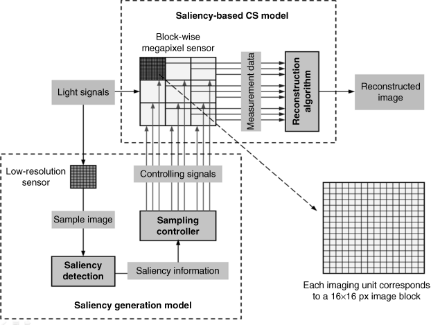
The overall structure of the saliency-based CS scheme is shown in Figure 8.12. There are two main models: a saliency generating model and a saliency-based CS model (see the two dashed rectangles in Figure 8.12). The saliency generation model employs a low-resolution complementary sensor, which can acquire a sample image of the input scene. Using this sample image and PCT model in the frequency domain can obtain the saliency map of the scene. The sampling controller computes the number of random measurements for each block by using Equations 8.54–8.55, and then controls the relevant block on the 2D optical grid array of the input image (the block-wise megapixel sensor) to perform random sampling. Each block on the 2D optical grid array has 16 × 16 optical grids, but only Mn grids are sampled by sensors. Note that in the proposed method, the row vectors in the measurement matrix are Dirac delta functions; that is, each row only has one non-zero element with value one, and the inner product between row vectors is zero. In this way, each block only needs to randomly sample Mn data by which the digital block image can be recovered from CS theory; in [82] the recovery of digital image uses orthonormal matching pursuit (OMP) in their experiments.
Figure 8.12 Architecture of saliency-based CS scheme [82]. © 2010 IEEE. Reprinted, with permission, from Y. Yu, B. Wang, L. Zhang, ‘Saliency-Based Compressive Sampling for Image Signals’, Signal Processing Letters, IEEE, Nov. 2010

Conventional CS approaches allocate sensing resources equally to all image blocks because they cannot discriminate which ones need to be sampled more or less. Using the reference frame to test the sparsity of each block often results in additional burden and the testing of reference frames may not correspond to the non-reference frame. Especially, for a still scene, the reference frame is not available. In saliency-based CS, the scene is analysed by exploiting the saliency information of the scene aided by a low-resolution sensor, and so the saliency-based CS scheme allocates more random measurements to salient blocks but fewer to non-salient blocks. Since the reconstruction algorithm in CS theory would offer better reconstruction quality of an image block with more measurements, the salient blocks can get more details of the interesting object, and significant regions have better quality. Thereupon, the quality of the recovered image by human perception for saliency-based CS is better than conventional CS under the same number of measurements for the whole image.
In [82], the simulation is for an image database [87] combining 120 colour images in a variety of urban and natural scenes. All images with 720 × 480 pixels in the database are converted to the bmp file format and the block size is 16 × 16 pixels (Ns = 256 in Equation 8.54). The saliency maps for all images with low resolution (72 × 48) are obtained by the PCT method, and then they are normalized and interpolated to a 720 × 480 greyscale map. The number of measurements for each block is assigned by Equations 8.54–8.55 for the all images in the database. Afterwards, each block in an image is compressively sampled with assigned sampling number and recovered by OMP for the known DCT basis matrix. Finally all reconstructed blocks are combined to form a full-size image for each image in the database.
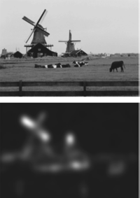
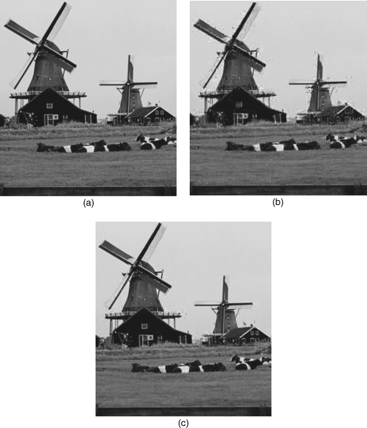
Three criteria of image quality assessment (IQA): peak signal-to-noise ratio (PSNR), mean structural similarity (SSIM) from [19] and visual information fidelity (VIF) from [27] were used to test the quality of the recovery of images in the database. The test results provided in [82] showed that the saliency-based CS scheme achieves higher scores of all IQA metrics than the case without saliency information in the same sampling rate for each complete image. To better illustrate the simulation result visually Figures 8.13 and 8.14 give an example of image recovery excerpted from [82]. The low-resolution image and its saliency map are shown in Figure 8.13. The size of original image (720 × 480 pixels) is cropped to 384 × 350 pixels for visibility.
Figure 8.13 The low-resolution image (upper) and its saliency map (lower) from [82]. Reproduced from http://worldislandparadise.com/ (accessed November 25, 2012)

Figure 8.14 (a) Original image copped to 384 × 350 for visibility; (b) the recovery of image (a) by CS without saliency information (sampling rate = 0.4); (c) the recovery of image (a) by CS with saliency information (sampling rate = 0.4) [82]. Reproduced from http://worldislandparadise.com/ (accessed November 25, 2012)

It is fairly obvious that the windmill and the cattle on the grass should have higher saliency, so the recovery of the image with saliency information has higher quality than that without saliency information. For conventional CS, a small amount of noise appears on the recovered image in Figure 8.14(b).
This section provides another application in compressive sampling for image acquisition. However, the idea is similar to image compression and image quality assessment: processing the salient regions and non-salient regions in a different way, the CS as a novel sampling theory has large potential for application in the future. Visual attention as a tool can be included within CS applications, which will help engineers to design more intelligent sensors for acquiring images and video.
