
i
i
i
i
i
i
i
i
668 26. Computer Graphics in Games
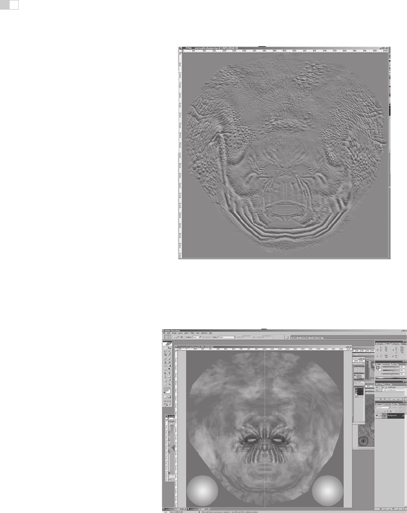
Figure 26.9. The normal map used in Figure 26.8. In this image, the red, green and blue
channels of the texture contain the X, Y, and Z coordinates of the surface normals.
Image
courtesy Keith Bruns.
(See also Plate XXXVI.)
Figure 26.10. An early version of a diffuse color texture for the mesh from Figure 26.8,
shown in Photoshop.
Image courtesy Keith Bruns.
(See also Plate XXXVII.)

i
i
i
i
i
i
i
i
26.5. The Game Production Process 669
Figure 26.11. A rendering (in ZBrush) of the mesh with normal map and early diffuse color
texture (from Figure 26.10) applied.
Image courtesy Keith Bruns.
(See also Plate XXXVIII.)
Figure 26.12. Final version of the color texture from Figure 26.10.
Image courtesy Keith
Bruns.
(See also Plate XXXIX.)

i
i
i
i
i
i
i
i
670 26. Computer Graphics in Games
Figure 26.13. Rendering of the mesh with normal map and final color texture (from Fig-
ure 26.12) applied.
Image courtesy Keith Bruns.
(See also Plate XL.)
If this additional detail were to be represented with actual geometry, millions
of triangles would be needed. Instead, the detail is commonly “baked” into a nor-
mal map which is applied onto the original, coarse mesh, as shown in Figures 26.8
and 26.9.
Besides normal maps, multiple textures containing surface properties such as
diffuse color, specular color, and smoothness (specular power) are also created.
These are either painted directly on the surface in the detail modeling application,
or in a two-dimensional application such as Photoshop. All of these texture maps
use the surface parameterization defined in the initial modeling phase. When the
texture is painted in a two-dimensional painting application, the artist must fre-
quently switch between the painting application and some other application which
can show a three-dimensional rendering of the object with the texture applied.
This iterative process is illustrated in Figures 26.10, 26.11, 26.12, and 26.13.
Shading
Shaders are typically applied in the same application used for initial modeling. In
this process, a shader (from the set of shaders defined for that game) is applied
to the mesh. The various textures resulting from the detail modeling stage are
applied as inputs to this shader, using the surface parameterization defined during
initial modeling. Various other shader inputs are set via visual experimentation
(“tweaking”); see Figure 26.14.
i
i
i
i
i
i
i
i
26.5. The Game Production Process 671
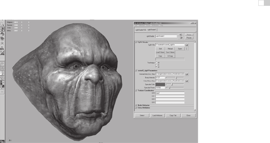
Figure 26.14. Shader configuration in Maya. The interface on the right is used to select
the shader, assign textures to shader inputs, and set the values of non-texture shader inputs
(such as the “Specular Color” and “Specular Power” sliders). The rendering on the left is up-
dated dynamically while these properties are modified, enabling immediate visual feedback.
Image courtesy Keith Bruns.
(See also Plate XLI.)
Lighting
In the case of background scenery, lighting artists will typically start their work
after modeling, texturing, and shading has been completed. Light sources are
placed and their effect computed in a pre-processing step. The results of this
process are stored in lightmaps for later use by the rendering engine.
Animation
Character meshes undergo several additional steps related to animation. The pri-
mary method used to animate game characters is skinning. This requires a rig,
consisting of a hierarchy of transform nodes that is attached to the character, a
process known as rigging. The area of effect of each transform node is painted
onto a subset of mesh vertices. Finally, animators create animations that move,
rotate, and scale these transform nodes, “dragging” the mesh behind them.
A typical game character will have many dozens of animations, correspond-
ing to different modes of motion (walking, running, turning) as well as different
actions such as attacks. In the case of a main character, the number of animations
can be in the hundreds. Transitions between different animations also need to be
defined.
i
i
i
i
i
i
i
i
672 26. Computer Graphics in Games
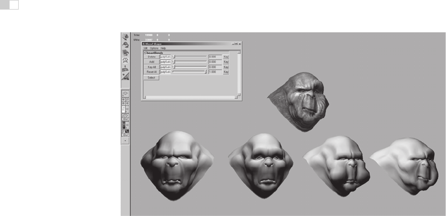
Figure 26.15. Morph target interface in Maya. The bottom row shows four different morph
targets, and the model at the top shows the effects of combining several morph targets
together. The interface at the upper left is used to control the degree to which each morph
target is applied.
Image courtesy Keith Bruns.
For facial animation, another technique, called morph targets is sometimes
employed. In this technique, the mesh vertices are directly manipulated to deform
the mesh. Different copies of the deformed mesh are stored (e.g., for different
facial expressions) and combined by the game engine at runtime. The creation of
morph targets is shown in Figure 26.15.
Notes
There is a huge amount of information on real-time rendering and game pro-
gramming available, both in books and online. Here are some resources I can
recommend from personal familiarity:
Game Developer Magazine is a good source of information on game develop-
ment, as are slides from the talks given at the annual Game Developers Confer-
ence (GDC) and Microsoft’s Gamefest conference. The GPU Gems and ShaderX
book series also contain good information—all of the former and the first two of
the latter are also available online.
Eric Lengyel’s Mathematics for 3D Game Programming & Computer Graph-
ics, now in its second edition, is a good reference for the various types of math
used in graphics and games. A specific area of game programming that is closely
..................Content has been hidden....................
You can't read the all page of ebook, please click here login for view all page.