
i
i
i
i
i
i
i
i
19.3. The Modelview-Controller Architecture 487
of our application window and then drag the mouse into our application
window. In this case, we will receive a mouse drag event without the cor-
responding mouse down event. For this reason, the mouse drag service
routine should check the invocation condition that the proper initialization
has indeed happened. Notice in Figure 19.8, we do not include proper in-
vocation condition checking. For example, in the LMBDragRoutine(),we
do not verify that LMBDownRotine() has been invoked (by checking the
DefiningNewHeroBall flag). In a real system, this may causes the program
to malfunction and/or crash.
19.2.5 Summary
In this section we have discussed programming models or strategies for organiz-
ing statements of our program. We have seen that for interactive applications,
where an application continuously waits and reacts to a user’s input actions, or-
ganizing the program statements based on designing control structures results in
complex and inefficient programs. Existing GUI systems analyze all possible
user actions, design control structures to interact with the user, implement default
behaviors for all user actions, and provide this functionality in GUI APIs. To
develop interactive applications, we take advantage of the existing control struc-
ture in the GUI API (i.e., the MainEventLoop()) and modify the default behaviors
(via event service routines) of user actions. In order to properly collaborate with
existing GUI APIs, the strategy for organizing the program statements should be
based on specifying user actions that cause changes to the application state.
Now that we understand how to organize the statements of our program, let’s
examine strategies for organizing functional modules of our solution.
19.3 The Modelview-Controller Architecture
The event-driven ball shooting program presented in Section 19.2.3 and Fig-
ure 19.8 addresses programmability and efficiency issues when interacting with a
user. In the development of that model, we glossed over many supporting func-
tions (e.g., UpdateSimulation()) needed in our solution. In this section, we de-
velop strategies for organizing these functions. Notice that we are not interested
in the implementation details of these functions. Instead, we are interested in
grouping related functions into components. We then pay attention to how the
different components collaborate to support the functionality of our application.
i
i
i
i
i
i
i
i
488 19. Building Interactive Graphics Applications
In this way, we derive a framework that is suitable for implementing general in-
teractive graphics applications. With a proper framework guiding our design and
implementation, we will be better equipped to develop programs that are easier to
understand, maintain, modify, and expand.
19.3.1 The Modelview-Controller Framework
Based on our experience developing solutions in Section 19.2, we understand that
interactive graphics applications can be described as applications that allow users
to interactively update their internal states. These applications provide real-time
visualization of their internal states (e.g., the free-falling balls) with computer
graphics (e.g., drawing circles). The modelview-controller (MVC) framework
provides a convenient structure for discussing this type of application. In the
MVC framework, the model is the application state, the view is responsible for
setting up support for the model to present itself to the user, and the controller
is responsible for providing the support for the user to interact with the model.
Within this framework, our solution from Figure 19.8 is simply the implementa-
tion of a controller. In this section, we will develop the understanding of the other
two components in the MVC framework and how these components collaborate
to support interactive graphics applications.
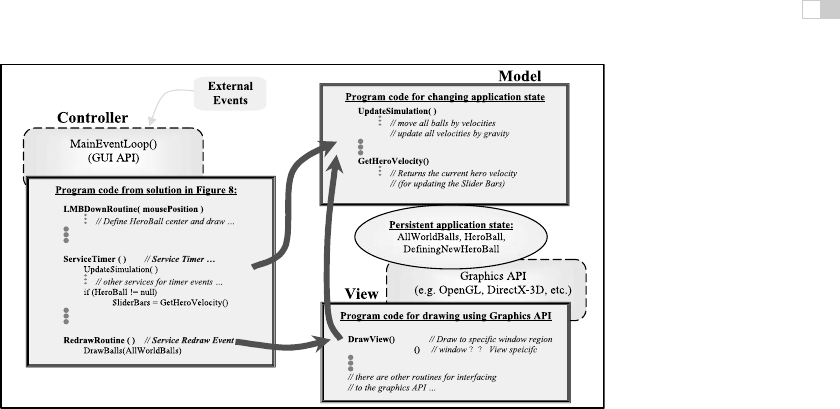
Figure 19.10 shows the details of a MVC framework to describe the behavior
of a typical interactive graphics application. We continue to use the ball shooting
program as our example to illustrate the details of the components. The top-right
rectangular box is the model, the bottom-right rectangular box is the view, and
the rectangular box on the left is the controller component. These three boxes
represent program code we, as application developers, must develop. The two
dotted rounded boxes represent external graphics and GUI APIs. These are the
external libraries that we will use as a base for building our system. Examples of
popular Graphics APIs include OpenGL, Microsoft Direct-3D (D3D), Java 3D,
among others. As mentioned in Section 19.2.2, examples of popular GUI APIs
include GLUT, FLTK, MFC, and Java Swing Library.
The model component defines the persistent application state (e.g., AllWorld-
Balls, HeroBalls, etc.) and implements interface functions for this application
state (e.g., UpdateSimulation()). Since we are working with a “graphics” ap-
plication, we expect graphical primitives to be part of the representation for the
application state (e.g., CirclePrimitives). This fact is represented in Figure 19.10
by the application state (the ellipse) partially covering the Graphics API box. In
the rest of this section, we will use the terms model and persistent application
state interchangeably.
i
i
i
i
i
i
i
i
19.3. The Modelview-Controller Architecture 489
TransformPoints
Figure 19.10. Components of an interactive graphics application.
The view component is in charge of drawing to the drawing area on the ap-
plication window (e.g., drawing the free falling balls). More specifically, the view
component is responsible for initializing the graphics API transformation such
that drawing of the model’s graphical primitives will appear in the appropriate
drawing area. The arrow from the view to the model component signifies that the
actual application state redraw must be performed by the model component. Only
the model component knows the details of the entire application state (e.g., size
and location of the free falling circles) so only the model component can redraw
the entire application. The view component is also responsible for transform-
ing user mouse click positions to a coordinate system that the model understands
(e.g., mouse button clicks for dragging out the hero ball).
The top left external events arrow in Figure 19.10 shows that all external
events are handled by the MainEventLoop(). The relevant events will be for-
warded to the event service routines in the controller component. Since the con-
troller component is responsible for interacting with the user, the design is typi-
cally based on event-driven programming techniques. The solution presented in
Section 19.2.3 and Figure 19.8 is an example of a controller component imple-
mentation. The arrow from the controller to the model indicates that most external
events eventually change the model component (e.g., creating a new HeroBall or
changing the current HeroBall velocity). The arrow from the controller to the
view component indicates that the user input point transformation is handled by
the view component. Controllers typically return mouse click positions in the de-
vice coordinate with the origin at the top-left corner. In the application model, it is
more convenient for us to work with a coordinate system with a lower-left origin.
i
i
i
i
i
i
i
i
490 19. Building Interactive Graphics Applications
The view component with its transformation functionality has the knowledge to
perform the necessary transformation.
Since the model must understand the transformation set up by the view, it is
important that the model and the view components are implemented based on the
same Graphics API. However, this sharing of an underlying supporting API does
not mean that the model and view are an integrated component. On the contrary,
as will be discussed in the following sections, it is advantageous to clearly dis-
tinguish between these two components and to establish well-defined interfaces
between them.
19.3.2 Applying MVC to the Ball Shooting Program
With the described MVC framework and the understanding of how responsibili-
ties are shared among the components, we can now extend the solution presented
in Figure 19.8 and complete the design of the ball shooting program.
The Model
The model is the application state and thus this is the core of our program. When
describing approaches to designing an event-driven program in Section 19.2.3,
the first two points mentioned were:
1. define the application state, and
2. describe how a user changes this application state.
These two points are the guidelines for designing the model component. In
an object-oriented environment, the model component can be implemented as
classes, and state of the application can be implemented as instance variables,
with “how a user changes this application state” implemented as methods of the
classes.
Figure 19.11 shows that the instance variables representing the state are typ-
ically private to the model component. As expected, we have a “very graphical”
application state. To properly support this state, we define the CirclePrimitive
class based on the underlyinggraphics API. The CirclePrimitive class supports the
definition of center, radius, drawing, and moving of the circle, etc. Figure 19.11
also shows the four categories of methods that a typical model component must
support.

i
i
i
i
i
i
i
i
19.3. The Modelview-Controller Architecture 491
class ApplicationModel {
private:
// Application’s private state
vector<CirclePrimitive> AllWorldBalls // World balls, initially empty
CirclePrimitive HeroBall // The Hero Ball
bool DefiningNewHero // If LMB drag is true
public:
bool IsDefinningHeroBall()
// If LMB drag is true, same as if we are in
// the middle of defiing the a new hero ball
bool HeroBallExists()
// Current hero ball is not null
int NumBallsOnScreen()
// Number of balls currently on screen
float HeroVelocityX()
// Hero’s velocity, x-component
float HeroVelocityY()
// Hero’s velocity, y-component
void CreateHeroBall (mousePosition)
// Creates new hero ball, with center at mousePosition
// radius and velocity are initialized to zero
void DragHeroBallTo (mousePosition)
// Refine radius and velocity of hero ball based on
// hero’s center and current mousePosition
void SetHeroBallVelocity (velocityX, velocityY)
// Sets current hero ball velocity
// if there is no current hero ball, nothing happens
void InsertHeroToAllWorld( )
// Done defining HeroBall, insert into WorldBallSet
void SelectHeroBall (mousePosition)
// Sets hero ball to be the one currently under
// mousePosition sets to null if none exists
void UpdateSimulation( )
// Move balls by their velocities, update velocity
// by gravity and remove off-screen ones
void RedrawApplicationState( )
// Draw all the freefalling balls (including the HeroBall)
// to the desired region on the application window.
}
1. Application
state inquires
2. Application
state changes
from user events
3. Application
state changes
from application
events
4. Application
state visualization
Class built on
Graphics API
Figure 19.11. The model component of the ball shooting program.
1. Application state inquiries. These are functions that return the applica-
tion state. These functions are important for maintaining up-to-date GUI
elements (e.g., status echo or velocity slider bars).
2. Application state changes from user events. These are functions that
change the application state according to a user’s input actions. Notice that
the function names should reflect the functionality (e.g., CreateHeroBall)
and not the user event actions (e.g., ServiceLMBDown). It is common for
a group of functions to support a defined finite state transition. For exam-
..................Content has been hidden....................
You can't read the all page of ebook, please click here login for view all page.