

i
i
i
i
i
i
i
i
19.4. Example Implementations 507
class MainUIWindow : public CDialog {
Model *TheModel; // The application State (Figure 11)
LPDIRECT3D9 TheGHC; // This is the Graphics Hardware Context
CWndD3D *LargeView; // These are View/Controller pairs that understand drawing
CWndD3D *SmallView; // with D3D (GDC) and UI element events (controller)
CSliderCtrl XSlider, YSlider; // These are the GUI elements
CStringEcho StatusEcho;
void OnTimer(); // Override the Timer service function
void OnHScroll( …); // Override the Scroll bar service function
};
Figure 19.25. MainUIWindow based on Microsoft Direct3D and MFC.
also supports interactive designing of the GUI element layout in (B), an area rep-
resenting the application window. Although the GUI builder interfaces operate
differently, we observe that in (C), the MFC resource editor also supports the
definition/modification of the physical appearance of GUI elements. However,
unlike Fluid, the MFC resource editor is tightly integrated with the rest of the
development environment. In this case, a developer can register for event ser-
vices by inheriting or overriding appropriate service routines. The MFC resource
editor automatically inserts code fragments into the application source code sys-
tem. To support this functionality, the application source code organization is
governed/shared with the GUI builder; the application developer is not entirely
free to rename files/classes and/or to re-organize implementation source code file
system structure. MFC implements internal direct code modification for event
service linkage, as described in Section 19.4.1.
Figure 19.25 shows the MainUIWindow implementation with Direct3D and
MFC. In this implementation, graphics operations are performed through Di-
rect3D while user interface operations are supported by MFC. Once again, The-
Model is the application state as detailed in Figure 19.11. LPDIRECT3D9is
the Graphics Hardware Context (GHC) interface object. This object is created
and initialized in the MainUIWindow constructor (not shown here). The two
CWndD3D objects are defined to support drawing with Direct3D. We notice that
one major difference between Figure 19.25 and Figure 19.22 is in the GUI ele-
ment support. In Figure 19.25, we see that the GUI element objects (e.g., XSlider)
and the corresponding service routines (e.g., OnHScroll()) are integrated into the
MainUIWindow object. This is in contrast to the solution shown in Figure 19.22
where GUI elements are grouped into a separate object (e.g., the UserInterface
object) with callback event service registrations. As discussed in Section 19.2.4,
MFC is an example of a large commercial GUI API, where many event services
are registered based on object-oriented function overrides (e.g., the OnHScroll()
and OnTimer() functions).

i
i
i
i
i
i
i
i
508 19. Building Interactive Graphics Applications
/
/ CWnd is the MFC base class for all window objects. Here we subclass to create a D3D output
// window by including a D3D Graphics Device Context.
class CWndD3D: public CWnd {
LPDIRECT3DDEVICE9 D3DDevice; // This is the D3D Graphics Device Context (GDC)
Model *TheModel; // The application state
void InitD3D(LPDIRECT3D9); // Create D3DDevice (GDC) to connect to GHC
void RedrawView() { // Draws the Application State
// Compute world coordinate to device transform
D3DMATRIX transform = ComputeTransformation();
D3DDevice->SetTransform(D3DTS_WORLD, &transform);
// Programming the D3D_WORLD matrix with the computed transform matrix
D3DDevice->Clear( bgColor, D3DCLEAR_TARGET);
D3DDevice->BeginScene();
TheModel->DrawApplicationState(D3DDevice);
D3DDevice->EndScene();
D3DDevice->Present();
}
void HardwareToWorldPoint(CPoint hwPt, float &wcX, float &wcY);
// Transform mouse clicks (hwPt) to world coordinate (wcX, wcY)
void OnLButtonDown(CPoint hwPt); // Override mouse button/drag service functions
};
Figure 19.26. CWndD3D: Direct3D/MFC view/controller pair.
CWndD3D is a sub-class of the MFC CWnd class (see Figure 19.26). CWnd
is the base class designed for a generic MFC window. By sub-classing from this
base class, CWndD3D can support all default window-related events (e.g., mouse
events). The LPDIRECT3DDEVICE9 object is the D3D Graphics Device Con-
text (GDC) interface object. The InitD3D() function creates and initializes the
GDC object and connects this object to the LPDIRECT3D9 (GHC). In this way,
a CWndD3D sub-class is a basic view/controller pair: it supports the view func-
tionality with drawing via the D3D GDC and controller functionality with input
via MFC. The RedrawView() function is similar to the draw() function of Fig-
ure 19.23 where we first set up the rendering state (e.g., bgColor and matrix),
including programming the matrix processor (e.g., D3DTS
WORLD), before call-
ing the model to draw itself.
In conclusion, we see that Figure 19.20 represents an implementation of the
solution presented in Section 19.3.3 while Section 19.4.3 presented two versions
of the implementation for Figure 19.20. Although the GUI Builder, event service
registration, and actual API function calls are very different, the final program-
ming source code structures are remarkably similar. In fact, the two versions
share the exact same source code files for the Model class. In addition, although
the drawing functions for CirclePrimitive are different for OpenGL and D3D, we
were able to share the source code files for the rest of the primitive behaviors (e.g.,

i
i
i
i
i
i
i
i
19.5. Applying Our Results 509
set center/radius, travel with velocity, collide, etc.). We reaffirm our assertion that
software framework, solution structures, and event implementations should be
designed independent of any APIs.
19.5 Applying Our Results
We have seen that the event-driven programming model is well suited for design-
ing and implementingprograms that interact with users. In addition, we have seen
that the modelview-controller framework is a convenient and powerful structure
for organizing functional modules in an interactive graphics application. In devel-
oping a solution to the ball shooting program, we have demonstrated that knowl-
edge from event-driven programming helps us design the controller component
(e.g., handling of mouse events, etc.), computer graphics knowledge helps us de-
sign the view component (e.g., transformation and drawing of circles, etc.), while
the model component is highly dependent upon the specific application (e.g., free
falling and colliding circles). Our discussion so far has been based on a very sim-
ple example. We will now explore the applicability of the MVC framework and
its implementation in real-world applications.
19.5.1 Example 1: PowerPoint
Figure 19.27 shows how we can apply our knowledge in analyzing and gaining
insights into Microsoft PowerPoint,
2
a popular interactive graphics application. A
screen shot of a slide creation session using the PowerPoint application is shown
at the left of Figure 19.27. The right side of Figure 19.27 shows how we can
apply the implementation framework to gain insights into the PowerPoint appli-
cation. The MainUIWindow at the right of Figure 19.27 is the GUI window of
the entire application, and it contains the GUI elements that affect/echo the entire
application state (e.g., main menu, status area, etc.). We can consider the MainUI-
Window as the module that contains TheModel component and includes the four
view/controller pairs.
Recall that TheModel is the state of the application and that this component
contains all the data that the user interactively creates. In the case of PowerPoint,
the user creates a collection of presentation slides, and thus TheModel contains all
the information about these slides (e.g. layout design style, content of the slides,
2
Powerpoint is a registered trademark of Microsoft.

i
i
i
i
i
i
i
i
510 19. Building Interactive Graphics Applications
Figure 19.27. Understanding PowerPoint using the MVC implementation framework.
notes associated with each slide, etc.). With this understanding of TheModel com-
ponent, the rest of the application can be considered as a convenient tool for pre-
senting TheModel (the view) to the user and changing TheModel (the controller)
by the user. In this way, these convenient tools are precisely the view/controller
pairs (e.g., ViewController components from Figure 19.16).
In Figure 19.27, each of the four view/controller pairs (i.e., OverviewPane,
WorkPane, StylePane, and NotesPane) presents, and supports changing of differ-
ent aspects of TheModel component:
• OverviewPane. The view component displays multiple consecutive slides
from all the slides that the user has created; the controller component sup-
ports user scrolling through all these slides and selecting one for editing.
• WorkPane. The view componentdisplays the details of the slide that is cur-
rently being edited; the controller supports selecting and editing the content
of this slide.
• StylePane. The view component displays the layout design of the slide
that is currently being edited; the controller supports selecting and defining
a new layout design for this slide.
• NotesPane. The view component displays the notes that the user has cre-
ated for the slide that is currently being edited; the controller supports edit-
ing of this notes.
As is the case with most modern interactive applications, PowerPoint defines an
application timer event to support user-defined animations (e.g., animated se-
i
i
i
i
i
i
i
i
19.5. Applying Our Results 511
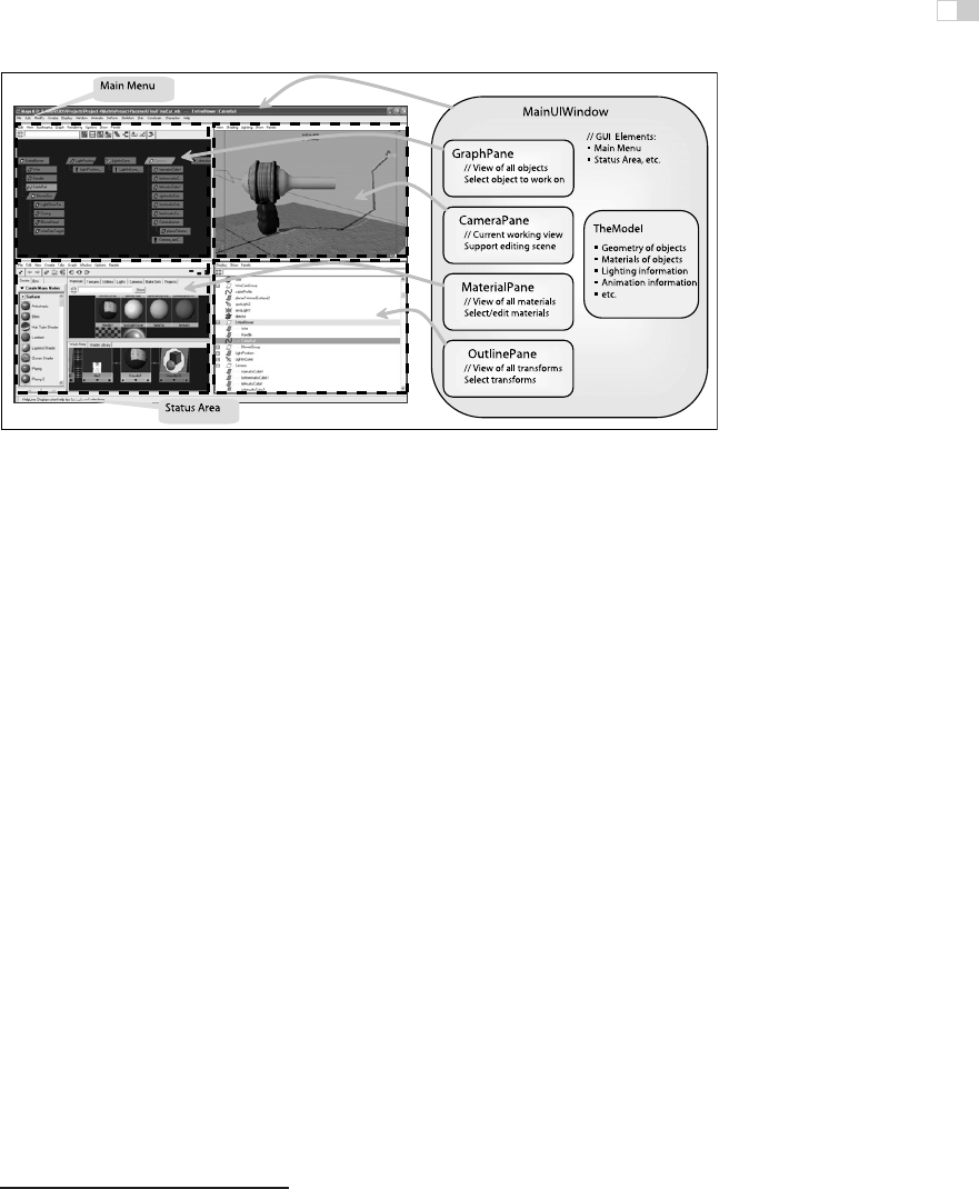
Figure 19.28. Understanding Maya with the MVC implementation framework.
quences between slide transitions). The coherency of the four view/controller
pairs can be maintained during the servicing of this application timer event. For
example, the user works with the StylePane to change the layout of the current
slide in TheModel component. In the meantime, before servicing the next timer
event, OverviewPane and WorkPane are not aware of the changes and display an
out-of-date design for the current slide. During the servicing of the timer event,
the MainUIWindow forces all view/controller pairs to poll TheModel and refresh
their contents. As discussed in Section 19.3.4, since the timer events are typically
triggered more than 30 times in a second, the user is not be able to detect the brief
out-of-date display and observes a consistent display at all times. In this way, the
four view/controller pairs only need to keep a reference to TheModel component
and do not need to have any knowledge of each other. Thus, it is straightforward
to insert and delete view/controller pairs into/from the application.
19.5.2 Example 2: Maya
We now apply our knowledge in analyzing and understanding Maya
3
,aninter-
active 3D modeling/animation/rendering system. The left side of Figure 19.28
shows a screen shot of Maya in a simple 3D content creation session. As in the
case of Figure 19.27, the right side of Figure 19.28 shows how we can apply
the implementation framework to gain insights into the Maya application. Once
again we see that the MainUIWindow is the GUI window of the entire application
3
Maya is a registered trademark of Alias.
..................Content has been hidden....................
You can't read the all page of ebook, please click here login for view all page.