
CHAPTER 3

How Do Living Objects Really Move?
Richard Lapidus
Rule: Weight in motion
Rule: Timing
After Completing This Chapter, You Will be Able To:
• Set keys with the right tangent type.
• Learn how to locate and identify the location of key frame information.
• Use the Key Info of a keyframe to adjust the position of an object.
• Use the Curve Editor to access curves.
• Use the Parameter Curve Out-of-Range Types to create repetitive motion.
• View and adjust the timing of an object’s motion.
Living objects move on curves and have a certain definable rhythm. When a line goes flat, it either represents calmness and tranquility or that the subject is dead. This chapter will explore a variety of timing factors that will enhance the realism of motion. Some of those factors are affected by weight, acceleration, deceleration, and exaggerated movement. One of the basic exercises in learning the timing of traditional animation is getting a ball to bounce and then trying to give it some life. Following up with the controls we explored in the first chapter, you will be introduced to a few more concepts for managing the interface and the basic functionality of starting to animate. Although this is a very basic tutorial at face value, the ability to “see” animation in terms of how it is stored in 3ds MAX is invaluable. I have developed this tutorial in the past few years based on responses from my students using a 3d program for the very first time. It is essential that you are able to “see” how animation is stored and why things work the way they do. There are more sophisticated ways to rig or script a ball bouncing, but this chapter will give you a good basis for controlling your work.
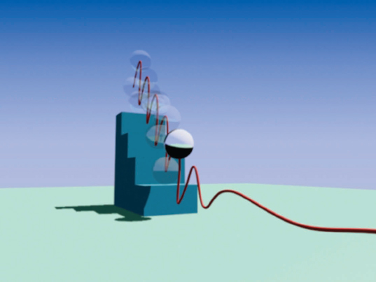
FIG 3.1
We are going to start with building a set of steps to for the ball to bounce down. This will introduce you to the Grid and Snap settings as well as some basic navigation controls. This book is primarily based on the creation and adjustment of animation, but I did want to throw in some modeling here and there. Start with a new 3ds MAX file and make sure your Units Setup is at the default of Generic Units. This can be accessed in the Customize Menu. Most of the tutorials will be using Generic Units throughout the book.

FIG 3.2
Refer to Fig. 3.2 for steps 1–9.
1. Maximize front viewport (MinMax or ALT + W).
2. Use the Pan Tool and move the construction planes down and to the right.
3. Go to the Create Shapes Panel, choose line.
4. Enable Corner for the Initial and Drag Types.
I love using paths to control moving objects through space. We could also very easily create the motion path for the ball from spline objects in addition to using them to create 3d objects. In fact, that’s what we will be doing in the next chapter. There is a distinctive correlation between modeling and animation relative to the complexity used. The rule of thumb typically is that less is more. Fewer keys when animating and less complexity when modeling will impact the success of your projects. This hopefully will increase your chances of creating smoother animation with better rendering times. You can always change the parameters later on, but it makes sense to always think ahead 10–15 steps. The corner option you are selecting will cause straight interpolation in and out of the vertex with every click. Many new users will also click and drag the mouse when setting vertices that allows the user to change the way that the vertex controls the surrounding segment. The drag type will be set to Corner as well just in case you have a “heavy hand” to start with when creating vertices.
Note
Take a moment to open the Interpolation Rollout. The default number of steps is set to 6. Try to keep this number as low as possible unless you notice too many polygons being created in your work. For now, leave it at the default, but make a mental note that it is here. If you like, set the number to 0, which will drop the number of polygons created when the extrude modifier is added. Because no complexity is needed along the flat surfaces of the steps, you may want to reduce it and get into the habit of removing the complexity where it is not needed. You can always go back with an edit poly modifier for example and cut into more polygons. We will be back here several times throughout the book, and it is a key concept to learn.
5. Turn on Snaps and right click the Snap button.
6. Make sure you are snapping to grids.
7. Click from the 0,0,0 position and create a step that is 100 units tall and 100 units wide. (The lighter gray lines are 100 units apart.)
8. Do this four times.
Keyboard shortcut: Use the “I” key to pan the view as you draw.
9. Finish the line by adding one more vertex at the lower left corner of the steps and the last one back at the first vertex created. You will be prompted to close the spline.
10. Click Yes then right click to end the Create Line command.
Note
The Right Click command turns off the create mode. This is an essential skill that I mentioned in Chapter 1. If you don’t right click or choose one of the transforms, you are still in the create mode for the last object you were creating.
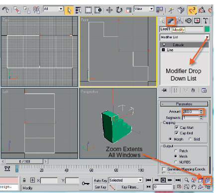
FIG 3.3
11. Add an extrude modifier with 130–200 units of height.
12. Hit Zoom Extents All icon in viewport controls
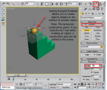
FIG 3.4
13. Go to Create Geometry, select Sphere, and enable Autogrid.
The Autogrid is a great feature for allowing you to snap the pivot of the object being created to the face normal of the object that your cursor is near. You will see the “Z” axis of the new objects pivot pointing 90 degrees from the face. We will talk about the orientations of axes later in the linking and constraint exercises. Aligning in the creation mode will save you a lot of time in trying to move and position objects after you have created them. It is important to note at this point that the sphere is probably one of the only objects that have a pivot set dead center. This makes sense in case you want to create something like a planet or a ball which pivots about the center without having to change it in the Hierarchy Panel. Later on when we look at the trajectory of the ball bouncing down the step, you will see that the trajectory is set in the center and not at the base. There is a work around for that later on in the chapter.
Note
Face normal and axis are two primary components of any 3d program. In 3d MAX, you are always working “X-Y” relative to view, and the “Z” axis is pointed away from the current construction plane. You could repeat that 10 times and still not get it unless you look at the world coordinates in the lower left corners of the viewports. When an object is created in any other orthographic view other than Top or the Perspective, the “Z” axis is pointed straight at you. When you go to move the object, the axis is relative to world again unless you change the pivot coordinate system back to Local to the object. This is not really that important unless you are going to be constraining the object or using it a hierarchy link system. This will be covered in a later chapter when we set up a simple character rig. I have a separate tutorial that covers these basic concepts of the coordinates system and cloning, which will be posted on the web.
14. Turn off Snaps. (Click the Snap button or hit the “S” key on your keyboard.)
15. Create a sphere on the top stair with a radius of about 50.
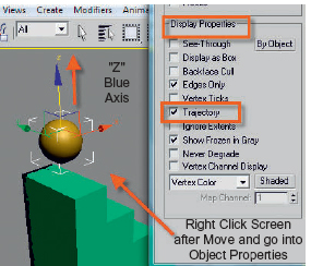
FIG 3.5
16. Move it up on the “Z” axis.
17. Right click the screen with the sphere still selected and turn on trajectory in the objects properties.
18. Enable the front viewport and bring it full screen.
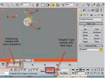
FIG 3.6
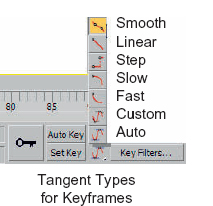
FIG 3.6a
The goal is to create just three keys and then have the software perform repetitions of these keys to bounce down to the floor. You could select the keys and shift move them in the timeline to create copies, but that gets very laborious and hard to control when you start working in longer animation segments. We are going to use the computer to do what it does best—repetitive functions. For this, we will be using the Param Out-of-Range Repeats. This may be your first introduction into controllers, which are very powerful tools in a 3d program. There is a trap to use here, but I will show you how to turn it off and then do some forward animation work. Typically I would use this on an object that spins forever, has a constant motion, or has a way of controlling the speed of some transformations.
19. Change tangent types of keys to smooth. See Fig. 3.6A for a listing of the tangent types in the flyout.
The smooth tangent type will give us a little bit of bend moving into and out of the keyframes. You may notice that the white dots along the tangent of the trajectory that represent the frames in between the keyframes are bunched together a little more as they get closer to each keyframe. This can be exaggerated with other tangent types as well.
Note
By setting the tangent type before you create keyframes, any new keys will interpolate the transition between keyframes using that control. Of course, you will want to experiment with these, and they can always be changed later on in Graphic Editors, Mini-Curve Editor, or key info dialog boxes. Only one of these which I rarely use is the Step Tangent Type. Step will maintain an object property until it reaches the time of another keyframe and will then change to it on that frame. Take a look at the second hand on a clock, it will seem to stay in position and then snap to the next second.
20. Turn on Auto Key.
21. Move the ball up in the air and behind the steps. Make sure you are at frame 0 when you do this. See Fig. 3.6 for the approximate position of the three keys that you will be creating.
22. Got to frame 10 and move the ball up and to the right.
23. Got to frame 20 and move it down onto the first step.
Take a moment to imagine the balls trajectory repeating four more times downward to hit the floor. Unless the offset from the third key to the first key is exact, repeating the keys will result in the ball not hitting the steps or going through them. You will see this in the next step when we turn on the Param Out-of-Range Repeat.
24. Go to the Graphic Editors Menu and open the Trackview; Curve Editor. If you use the icon in the Main Toolbar, that will be the default of the two editors.
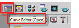
FIG 3.7
25. Pan the list of objects until you see the ball that has all three move transforms highlighted in yellow. See Fig. 3.8. By default, any selected object with an animated transform like move will show as selected in yellow.
26. Make sure you expand and highlight all three of the X, Y, and Z Position Tracks.
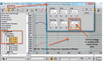
FIG 3.8
27. Go to the Controller Menu and choose Param Out-of-Range Types.
28. Click Relative Repeat graph. Hit OK to exit Dialog and show marquee continued curves.
Notice how the balls trajectory continues into and out of the three set of keys. There are two parts to the repeats represented by the arrows below the small curve diagrams. Those buttons as shown in Fig. 3.8 represent the area before and after a set of keys. By default the Constant is on for both sides of a set of keys. By clicking the diagram image, you are setting both to the same “in and out” type. Let’s say you wanted an object to sit in position for a number of frames before moving and then repeating. You would leave Constant on for the left side and choose a different type for the outside. Of course, you would not want a key at frame 0.
29. Turn off Auto Key.
30. Minimize this editor and go to frame 100.

FIG 3.9
31. Hit “M” to open the Material Editor. Go to modes and change to Compact, so it looks like the image in Fig. 3.9.
32. Click the None button for the diffuse map channel. (Fig. 3.9 shows a checker map already assigned.)
33. When the Map Browser appears, choose checker as the map type.
34. Drag the Material onto the ball or use the Assign to select icon. Turn on and show in viewport as well.
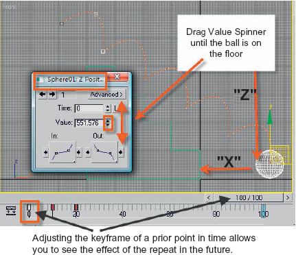
FIG 3.10
Scrub the timeline a few times and notice how the ball misses the steps. The trajectory is on but is no help in visualizing the ball hitting the steps because it is located in the center of the object. Make sure you return to frame 100 before proceeding to the next step. We are going to control the position in the future by adjusting the first key. As you will find in exploring the program in more depth, there are dozens of controls accessible through the right mouse button. The one we will explore next will allow you to access a keyframes numeric value and tangency type.
35. Left click the key at frame 0 to select it. (Selected keys turn white.)
36. Now right click the white key at frame 0 and choose “sphere01 Z position”.
37. Adjust the key value spinner until the ball is on the ground at frame 100. Close this Key Properties Dialog.
38. Right click the red key at frame 0 and choose “Sphere01 X Position”.
39. Adjust the key value slider until the ball is in front of last step. Close this Key Properties Dialog.
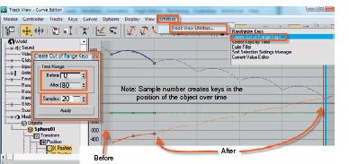
FIG 3.11
In the next few steps, we are going back into the Curve Editor to “bake” some keys in for the range of frames after your hand-keyed animation. If you spin your middle mouse button over the graphic curve of the Editors Dialog, you may notice that the balls trajectory continues on forever. Actually you can’t see this in the main viewport because only 100 frames are currently active. A ball bouncing down steps would normally continue bouncing across the floor but not through it. Then again … there was this time I was playing with a bowling ball at home upstairs … that’s another story for another day. After “baking” in keys where the repeat is working, we will turn off the Param Type and hand key the rest of the animation. This will give you a good opportunity to experiment with the different key tangent types.
40. Go back to the Utilities Menu and drag out to Track View UtilitiesChoose Out of Range Tangents. Note the image above.
41. Pick Create Out of Range Keys from the menu.
42. Put 0 in Before, 80 in After, and 20 in Samples. Click Apply.
There are 100 keys in the animation so far with 20 taken up for with the hand keying of the first 20 frames. By adding 20 samples after, you are defining the curves of the “baked” trajectory with 20 keys. See the baked trajectory in Fig. 3.12. Take a moment to experiment with different values if you like. You can undo this operation with a CTL + Z and redo steps 40–42. If the values are too high or low, the motion will be choppy.
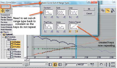
FIG 3.12
43. Go back to Controllers and change the Out-of-Range types back to Constant.
44. Close the Curve Editor.
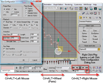
FIG 3.13
There are two basics ways to increase the active time segment, so that your animation will be longer than the default 100 frames. Access the Time Configuration Panel by right clicking the play buttons or left clicking the Time Configuration Dialog icon. My preferred method is simply to hold the CTL + ALT keys and drag the right mouse button until the desired amount of frames is active. Figure 3.13 shows panning and increasing the negative values as well.
Note
If you do show active negative frame values, make sure you do not render them as a single frame to compile later. They will not increment before frame 0, but show as a dash value amount. All work to be rendered should be with positive value keys.
45. Right click any play button to enter Time Configuration.
46. Increase the number of frames to 150.
47. Move the time slider to frame 150.
48. Turn on the Auto Key.
49. Go to Frame 150.
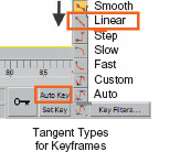
FIG 3.14
50. Change the Key Tangent to linear and move the ball across the screen. Notice how the ball dips below the floor and note the trajectory curve.
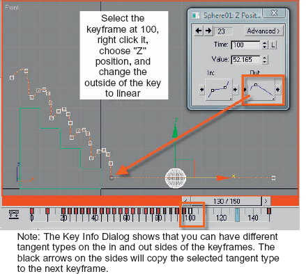
FIG 3.15
51. Select the key at frame 100. Right click the key, choose “Z” position and change just the outside of the key to Linear.
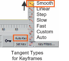
FIG 3.16
52. Now set the Default Tangent for new keys back to Smooth Curve.
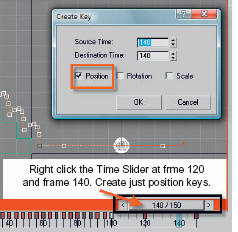
FIG 3.17
53. Move every 20 frames between 100 and 150 and right click time slider, creating just Position Keys.
54. Go to frames between the right-clicked keys and move up slightly on the “Z”.
55. Go to frame 20. Rotate the sphere. Go to Mini-Curve Editor or track view and give the rotation transform track a relative repeat-out-of range.
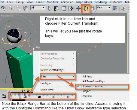
FIG 3.18
56. Right click the timeline. Choose Filter and then choose Current Transform. This will let you see only the two Rotation Keys.
Play the animation. If the rotation is too fast, move the second key to the right. If it is too slow, move it to the left.