
CHAPTER 1

Introduction to the Interface and Seeing Animation in a New Way
Richard Lapidus
After Completing This Chapter, You Will be Able To:
• Start to develop the basics of visualizing animation in a 3d program.
• Understand the different ways to create and control animation.
• Have several choices in selecting and editing keys.
• Control how you see and control motion.
Every few years a study is done that correlates the benefits of playing computer games and improved learning skills. I will wholeheartedly agree that there are benefits that may include improving memory, problem-solving abilities, and motor skills. Unfortunately, the areas that generally need work have to do with visualization, perception of space, and a good sense of timing. The goal is to create a world in which the viewer will be drawn in and immersed with in the reality presented to them. As we journey through this book together, hopefully you will develop the skills or at least a basic understanding of how to start “perceiving” motion and using those skills to create animation. Anyone can create motion with keyframes, but a true animator will breathe life into a character and give it some level of realism relative to its own reality. As a starting point, we will cover some of the basic tools you need to control the 3d environment you are working in. Try to think of the first few chapters as a quick start to understanding the basic workflow of 3ds MAX. Instead of giving you a fully extensive explanation of every single icon and command to start, I want to “pull you in” and get you moving toward seeing how things work. The best analogy I can give you for not expounding for 10–15 pages of parameters is relative to learning how to drive a car. Although I know one or two people who have, most of us didn’t sit down and read the owner’s manual of a car before learning how to drive.

FIG 1.1
The first thing I want you to do is change the user interface to look similar to the images in this book. The “dark” version, which is the default, is nice in a low-light environment, but it is hard to see the subtle changes to some of the interface as you work.
1. Start up 3ds MAX and go to the Customize Menu. Choose User Interface and select the AME Light Version. Hit OK to accept and the next time you start 3ds MAX, it will be the default color scheme.
2. Notice how some of the icons and parts of the interface have a yellow background or border. This indicates an active state. You should see the Select icon; create geometry and the perspective view as being currently active.
3. Let’s start by maximizing the perspective view. There are actually three ways to do this. Those are with keyboard shortcut ALT+W, the minmax icon, or dragging the upper left corner of the viewport. You will find that there are usually three to five different ways to accomplish the same thing with the program.
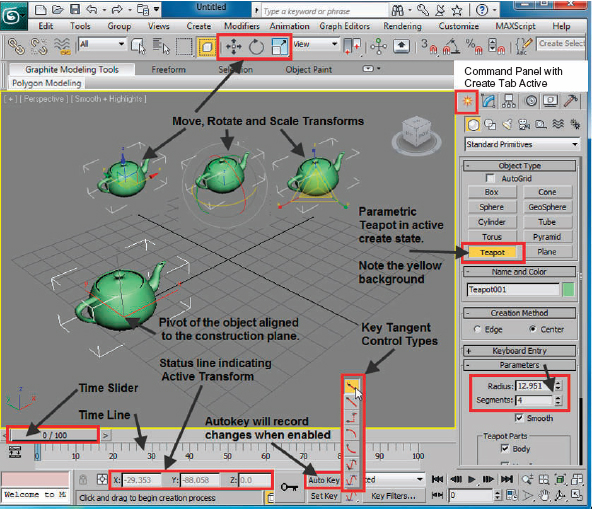
FIG 1.2
Refer to Fig. 1.2 for steps 4–9
4. In the Command Panel, enable the Standard Primitive called teapot and drag out an object of about 30-unit radius.
5. Right click the screen or choose one of the selection modes. (If you don’t turn off Create mode, it is still active and you might endlessly be creating objects.)
6. Left click on the three select transform icons in the main toolbar and then finally on the Select and Move transform. Notice how the transform gizmo changes depending on if you are in Move, Rotate, or Scale mode.
The program gives you visual feedback as to what is active in a number of ways. The color red represents active animation state, the “X” axis, and the move transform. After creating keys (keyframes) in the next several steps, the transform keys will appear with the three basic color representations (red, green, and blue) much the same way it shows on the transform gizmo.

FIG 1.2a
7. Make sure the tangent control is set to Smooth which is its default tangent type.
8. Turn on the Auto Key and move the time slider to frame 100.
9. Move the teapot across the screen on the “X” axis. (Note: You could also drag the “X” spinner down in the status line. This is preferable when an object is selected and you want to avoid having to grab the transform gizmo.)
10. Move the time slider to frame 50 and then move the teapot up on the “Z” axis.
11. Play the animation.
You will see that there are three red rectangles now located in the timeline at the bottom of the interface. Keys on a straight line represent, at least in my mind, linear motion, tranquility, or death. One of the rules of thumb for starting to breathe life into your object or scene is to start looking for the curves. Living things tend to move on curves while mechanical motion is more linear or too precisely repetitive. The best analogy for this is a heart monitor you might seem in some TV drama. What happened when the EKG line goes flat? It means the patient is dead. The inverse is also true. Ever notice when the stage has been set to see if someone can be revived? The blipping does not come back all at once. There is an irregularity in the tempo of the graphic until it reaches some moment of repetition before the camera cuts to another actor or scene. Let’s look at a few ways to visualize the motion.
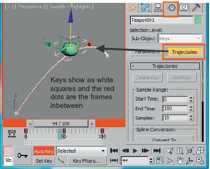
FIG 1.3
12. With the teapot still selected, go to the Motion Panel. It is the fourth tab in the Command Panel. Please see Fig. 1.3.
13. Click the trajectory tab.
What will appear is a red line with three white squares. The squares represent a value of the X, Y, Z position for the object in time, and the dots represent the frames in between the keys you created. Normally I will turn on the trajectory in the Object Properties because this way of displaying the motion of the object visually is only temporarily on while the object is selected. It is nice to note, however, that the motion of the object can be converted to a path which can be used for generating a 3d object or as a path constraint as just two examples. This will be done in a later chapter, but this is how I created the motion in Fig. 1.5 for one of my colleagues teaching a complex calculus problem his students were having difficulty visualizing. For any instructors using this book, a good exercise for practice is creating visuals for other curriculum.
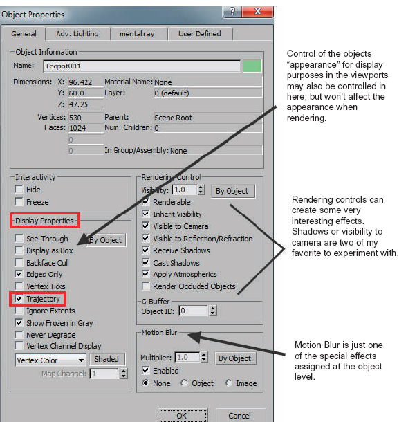
FIG 1.4
14. Right click the viewport and when the Quad Menu shows up, choose Object Properties. Then on the left side of the Dialog in the Display Properties area, enable Trajectory.
The Quad Menu and Object Properties are two tools you will want to get very well acquainted with. The Quad Menu will change and is customizable as you make changes to your objects. Since the teapot is still parametric, only half of the menu appears. If it were converted to an editable object or had a modifier on it, you would see all four panels. The Object Properties Dialog has more uses than we would want to explore in an introductory chapter, but will be explored in more detail in later chapters.
15. Leave all these preferences in the default state for now except the trajectory on and hit the OK button.
Select the key at frame 50 and drag it to frame 70. Notice how the trajectory changes. There is a built in smoothness and stretchiness to the default tangent controller for the keys created. Move the key to frame 40 and examine the trajectory again. The teapot seems to go beyond the position it is traveling to and then through the key as it moves to the next position. There are several ways to adjust this…but first you needed to see it to believe it. The next way to see the motion of your object is with a graphic editor. There are actually four other ways to see the motion in numeric, range, or line form. Those are Mini-Curve Editor, dope sheet, and the Curve Editor or key values. We will be using all of them through the book except for the Mini-Curve Editor. I find that it always needs panning or zooming to deal with, so I will only show you it once.

FIG 1.5
16. Click the icon for the Mini-Curve Editor in the lower left corner of the interface. You now see all the curves for your teapot. Drag a marquee around all the keys and then click linear tangent. The curve editor must be closed before the change in motion will show in the viewport. Notice how the teapot now moves on straight lines.
For changing and viewing the tangent types in the next few steps, refer to Fig. 1.2A, which shows the names of the different tangent types in the flyout. I typically will change the tangent type to the one I want before creating animation keys, but they always need to be adjusted at some point in time anyway. I find it easier to memorize as a vertical rather than horizontal list.
17. Click the Step Tangent with all the keys selected. The teapot stays in position and now snaps in one frame to the next position. Nothing I can think of moves like this except for the second hand on a clock. With the dominance of smart phones, the only second hand in my classroom this year was on the wall clock. Not a single person was wearing a watch with a second hand except for me.
18. Try the custom tangent type and then adjust the grips as you would the controls on a vertex in sub-object.
19. Return the keys to the default smooth and close the Mini-Curve Editor.
20. Hit the “F” Key on your keyboard and change the perspective view to a front view.
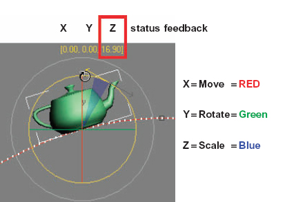
FIG 1.6
21. Move the time slider to about frame 35 and enable the Select and Rotate Tool or right click and select Rotate from the Quad Menu.
22. Drag the “Z” axis that should be the center circle so the teapot looks like it is sitting on its own trajectory. The “Z” axis is shown in yellow in Fig. 1.6. When the Reference Coordinate System is set to View the “Z” axis is always perpendicular to the orthographic viewport.
23. Move the Time Slider to about frame 70 and rotate it forward so it looks like it is sitting on its trajectory on the other side. Play the animation.
The teapot appears to be picking up from frame 0 and then rotates around the apex of the curve. It maintains the rotation all the way through to frame 100. Since a key isn’t out in the future to interpolate to, the motion stays all the way through from 70–100. Also notice how the Rotation Keys are in green. I’ve shown you a key concept here that is “bracketing” your keys. By not having the Rotation Keys on the same frames as the move, you are getting a more complex and realistic motion. Everything doesn’t happen at the same time. There has to be some pre- or postmovement to telegraph the action. It’s like head turns and eye movements. Linear rotation would not work well with turning a head, and the eyes typically always start moving toward a target before the head. Let’s take a look at another really core tool for controlling your keys. We could grab the keyframes at zero and make a copy at frame 100 with the Shift Key. But the Move Key would copy also. We will do it selectively and then I’ll show you two more key features for controlling what you see.

FIG 1.7
24. Move the time slide to frame 100 and then right click the Time Slider. A Create Key Dialog will appear.
25. Uncheck the Position and Scale Radial button and then enter 0 for the source and 90 for the destination. Hit the OK button and you will see that the Rotation Key from frame 0 has been copied to frame 90.
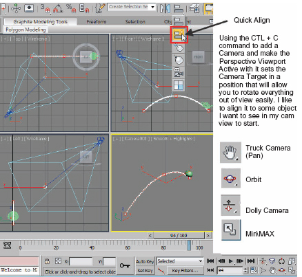
FIG 1.8
26. Change back to the perspective view by hitting the home button on the navigation cube and then execute a CTL+C command. This will create a camera view out of the perspective view.
27. MinMax the viewport for a moment and notice the placement of the camera and target. If you orbit the camera right now, it would be quickly out of view.
28. Hit the “H” Key to select the camera01 target by name.
29. Drag the flyout for the alignment tools for quick align (looks like a lightning bolt on the slanted cubes) and then left click the teapot. The target is now set so you can rotate around it to get a better view. Adjust your view with the icons indicated in your viewport controls to get a nice diagonal motion across the viewport.
One of the things that I like to do for visualizing motion in a still image is to take an objects trajectory and make it visible in the scene. I’ve also used this for creating paths out of moving objects and having these paths grow over time. When you start to think about having things appear or disappear, the options are endless. We will be looking more deeply into aspects of this in the Visibility chapter 16. For now, let’s look at converting motion into a spline, which can be rendered.

FIG 1.9
30. Select the teapot again either with a left click or “H” and select name.
31. Go into the Motion Tab of the Command Panel and Select Trajectories again.
32. The Start Time and End Time represent the range of keys you want to capture and create a spline from. The number of Samples represents the number of vertices that will be created in that new spline.
33. Hit the Convert To button and then select the spline from your scene called “Shape001”.
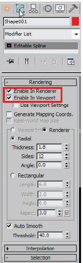
FIG 1.10
There are several things to note about spline objects that will help you in other areas down the line. In the Modify Panel, you will see that the Rendering Portion allows you to enable in Renderer and Viewport. Many modifiers like Turbo Smooth, which add complexity to an object can be set for low resolution in the viewport for navigation and then show when you render. Scene complexity becomes a problem with 3ds MAX, so you want to look for all the ways possible to maximize efficiency. Here is an example of how to save lots of resources. Imagine telephone or cable lines snaking through a scene. Instead of trying to model these as 3d objects, you can merely create splines which are no-poly count and make them renderable. I once demonstrated to a client five different ways to model a chair made out of tubes. In a scene requiring several hundred copies, any version became problematic. We ended up importing the polylines they were using as a base for modeling in another rapid prototyping program and just made them renderable. There was low scene complexity and the splines can even cast shadows. When working in the program, look for these time-saving features. Let’s look at a few other ways to visualize motion. Although you probably won’t use these tools exactly as shown, it will give you a good overview of functionality.
34. Make sure the Auto Key is off and make sure the teapot is still selected.
35. Hold the Shift Key and move the teapot about 100 units on the “Y” axis.
36. When the Clone Options Dialog appears, choose Copy as the type and hit OK.

FIG 1.11
Result
The Clone Options Dialog will appear. Shift is used with any transform (Move, Rotate, or Scale) will allow you to create clones of the object. In this case, it creates copies of the keys as well. If the Auto Key were still on, it would allow you to create a clone and create a new keyframe, while leaving the rest in the original position. This is interesting to experiment with. There are three options to choose from: Copy which creates an independent object, Instance which wires the objects together so that changes at the object level controls all other instances, and Reference which is a one-way connection. We will explore these in more detail later.
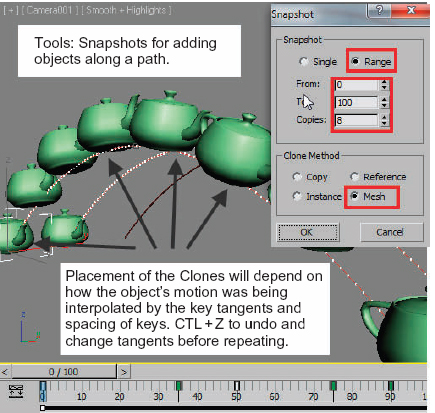
FIG 1.12
37. Go to the Tool Menu and try a Snapshot Command. This will allow you to create a number of copies distributed along the objects trajectory.
I will typically use Mesh and then bring the visibility down to 0.2 at the object level in properties or add a material with a value of 15%–20% opacity. For still images once again, this creates a nice easy solution. The next two solutions we will look at will be for getting your objects to show in a little more of a traditional method. The first solution will use ghosting, which is like the onion skin technique used by 2d paint programs to show before and after frames for reference as the animator would draw the frames. The other is motion blur which occurs at render time instead of in the viewport. The ghosting as shown in Fig. 1.13 displays a range of positions before and after the current frame in two different colors. I rarely use ghosting of the objects in wireframe because visually, there is too much information to really see what you may want to be looking at. Consider displaying the object as “box” when you are setting up the ghosting. A good example of what I am really looking to pick up is the swerve of a car through a turn that I want to exaggerate. It’s easier to eye up the changes of a simple extent box edge rather than all the complexity of your objects wireframes.
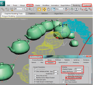
FIG 1.13
38. First go to the Views Menu in the main toolbar and enable ghosting. Ghosting will appear on any object selected in the scene. If you set this up and don’t see the effect, you may have de-selected an object.
39. Now go to the Customize Menu and choose Preferences.
40. Try 50 ghosting frames with 10 Display Nth Frame. Turn on Ghost Before and After to see the motion of where your object is coming from and going to.

FIG 1.14
41. Hit the “H” Key and select all of the teapots that were created as snapshots.
42. Right click the screen, and choose Object Properties and change the visibility to 0.2.
Trap
If you use mental ray as the rendering engine, it won’t render the object property visibility reduction. You will have to use a material with opacity or transparency adjusted.
43. Hit F9 to render your view. All the snapshots are semitransparent.
Up until this point I haven’t mentioned object naming conventions. When an object is created or cloned in some form you have the option of changing the name. As duplicates or new objects are created, they are incrementally named by the primitive. In a decent size scene, you could have several dozen cylinders which became telephone poles, and boxes which were formed into just about anything. In a working environment, collaborating with other animators and merging work together can be problematic if nothing is named. The problem cascades when you think about sending your scene out to a programmer for gaming. If you were playing around with creating extra clones, your selection might not include Teapot003-Teapot010. There are some wonderful options we will explore by assigning attributes later in the book. Your job will be easier if you get in the habit of sticking to a naming convention you can work with. For example: Flying_pot and flying_pot would actually be read as two distinct objects due to the capitalization. I suggest all lower case with an underline between each word. In the DOS days of animating we were limited to eight characters for file names. Keep is short and simple. In forensic cases that I worked on with pick-up truck and a semi-tractor trailer, I used as the main parent: pu_body and trk_body. Each had a listing of parts that started with a prefix of pu_ and trk_. There is even a tool in 3ds MAX that will let you swap in objects for stand-ins. Let’s continue to the last rendering option for your viewing pleasure. Let’s add some motion blur to the teapot.
44. Select the other teapot, and in the Object Properties, enable Motion Blur
45. Select the Camera01 and in the Modify Panel, go to the Multi-Pass Effect area and enable Motion Blur.
46. Go to the Create Panel and under systems, create a daylight system.
47. Hit F9.
48. Go to the Rendering environment and change the background color to a light gray or white.
49. Create a Plane object in the top viewport for casting shadows onto and then switch your view back to the camera view.
50. Hit the F9 key again and your scene should render something that looks like Fig. 1.1. There are some problems with that image relative to the defaults and the shadows, but we can look at fixing that later on.
Working in the trenches for teaching computer animation at the college and professional levels, I find myself relying on and referring back to traditional animation techniques, which for the most part were my only references when I started learning 3d animation back in the early 90s. Much has changed over the last two decades as to the power of the hardware and capabilities of the software, but essentially it is still a tool. To move toward a goal of being a good animator as one might aspire to be a good writer, you need to keep in the back of your mind that your most important asset needs to be exercised: the brain. A writer is told to write about what they know and then exaggerate it. As an animator, we are wearing many hats. Two of the basic areas that are a direct carryover from the traditional side of the world are to capture how things really move and then to try to figure out how to compose a story. If you aren’t drawing what you see every day, then you are missing a world of opportunities to graphically notate the world around you for future use. If you aren’t out hunting with a camera, the skills of composition, effects of lighting, and even depth perception may be getting rusty.