
CHAPTER 16

Animated Visibility
Richard Lapidus
Rule: Setting a scene
After Completing This Chapter, You Will be Able To:
• Animate an object out of view with the step-key tangent.
• Use the slice modifier to make an object appear or disappear.
• Utilize animated gradient ramps.
In traditional cell animation, it’s easier to make characters or things disappear. The object is simply not on film from one frame to the next or it is gradually faded out. The first is referred to as the pop-off screen solution. With the pop-off solution in traditional animation a character might fall in a hole, duck behind a tree much thinner than itself, or be hidden in a puff of smoke. In the early days of 3d animation, to have something disappear quickly, it would need to be animated off screen in one frame with an animated key or have an animated material map working. The problem with keying it off screen typically meant doing some extra adjustments to the TCB controlling the motion. In a 3d scene, although it’s just electrons, we need to control getting a “physical” 3d mesh within the scene. This chapter will cover a variety of interesting ways to do that using the tools inherent to controlling its presence with animation.

FIG 16.1
Animating an Object Out of View with the Step-Key Tangent
The first solution will demonstrate the pop-off concept and show you a little trickery with the key tangent types. It is simple to set the key tangent to step and move the object off the screen. This will keep it in place maintaining state until the next keyframe is encountered.
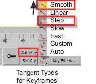
FIG 16.2
1. Load the file called chpt_17_visibility_start.max.
2. Select the blue teapot callved “Pop-Off”.
3. Make sure the Key Tangent is set to the default of Smooth.
4. Enable the “Auto Key”.
5. Animate the teapot moving across the screen at frame 50.
6. Set the Key Tangent to Step (third flyout down) and then move it off the screen at frame 75.
7. Right click the object and turn on its trajectory in the display properties.
8. Turn off the Auto Key.
9. Go to the Tools Menu and choose snapshot.
10. When the Dialog appears, enable range and set the number of copies to 10.
11. Hit OK and then choose the copied teapots with the “H” Key (pop-off001-pop-off010).
12. Right click the screen, and choose Object Properties from the Quad Menu.
13. Turn off Receive Shadows and Cast shadows. Hit OK to exit the Object Properties Dialog.
14. Add a standard gray material to the objects with two-sided rendering enabled on and the opacity set to around 25%.
Notice how the teapot moves across the screen for 50 frames, sits there for 25, and then pops off at frame 75. Looking at its trajectory, there is an apparent straight red line after frame 75 without any white dots representing the frames between your animated keys at frames 0 and 50. This is the crudest method for getting an object out of frame, but it does represent a motion we typically take for granted. Take a look at the second hand on your watch, it maintains state until the next state and then snaps into position. As we do need to use mechanical motions occasionally, it is still a noteworthy mention.
Keying is a fine art, which you undoubtedly will want to be practicing through many of the exercises. Let’s take a quick look at keying some of the built-in features for slicing an object at the parametric level before we move onto modifiers. Some of your parametric objects like the torus have built-in Slice features that can be animated as well. In the next few steps, we will animate the slice values of the torus to make it grow over time. We use this effect sometimes in reverse to do a quick reveal of an object instead of making it disappear. You can always swap the keys to accomplish this.
Animating Parametric Slicing
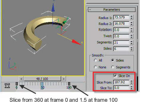
FIG 16.3
15. Select the torus object.
16. Set your Key Tangents back to default interpolation (top one).
17. Go to the Modify Panel.
18. Make sure Auto Key is off.
19. Turn on Slice Check box in the bottom of the panel.
20. Turn on Auto Key and go to frame 100.
21. Animate the Slice From value to 1.5 and the Slice To value to 0.0.
22. Go to frame 0.
23. Set the values to 360 for Slice From and 0.0 for the Slice To value.
Several other primitive objects like the cone, sphere, cylinder, and tube will allow for this type of animation at the parametric level. These can be used in combination with other modifiers and compound objects to create very interesting animated cutting effects. We will explore one variation of this next.
The process of using animated modifiers happens to be one of my favorites for gradually making an object build or hide over time. In this case, we will use an animated Slice Modifier. I’ve used this to show the building of a shell over time or removing part of an object when it is being disintegrated without using special extensive particle systems. I originally came up with the idea for my architectural clients to demonstrate a sort of time lapse in creating a building on site. Once my animation students started to get the idea … it became one of their favorites as well.
Animating Slice Modifier
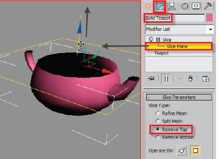
FIG 16.4
24. Make sure Auto Key is off.
25. Select the teapot called “SOLID Teapot”.
26. Go to the Modify Panel.
27. Add a Slice Modifier.
28. Go to the sub-object and choose the Slice Plane.
Note
The Slice Plane modifier will be aligned to the Transform Gizmo (axis) of the object along the “Z” axis. It basically is a planar mapping projection that can be not only moved, but rotated as well. Things don’t always neatly need to be sliced from top to bottom. You may want to experiment with adding a few rotation keys offset from the position key to create a little more realism. In the next few steps, we are going to animate this up over time along the “Z” axis so that the object appears to have a portion of the mesh on either side of the slice gizmo removed. Ever seen a character duck behind a thin tree or appear out of nowhere from behind something, this is how you would do it easily! It’s like pulling a rabbit out of hat. Something really big can appear to be in a very small space.
29. Set the Slice type to remove top.
30. Turn on the Auto Key.
31. Move the Time Slider around frame 80.
32. Move the slice plane above the teapot on the “Z” axis about 80 units so the teapot is completely revealed.
34. Turn off the sub-object slice plane.
35. Go to the Edit Menu and choose the Clone command (CTL+V).
36. Choose Copy as the type and call the new pot Wire Teapot.
37. Choose Remove Bottom for the Slice Type.
38. Open the Compact Material Editor.
39. Assign a material and turn on Wire and Two Sided in the Shader Basic Parameters area.
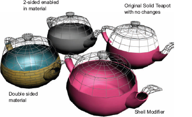
FIG 16.5
Note
Step 38 has three alternative solutions you can use to make your object appear to have an inside surface of the original object. By default, if you rendered at around frame 40, you would be seeing through the backside of the teapot because the normals are only rendering the outside surface. Using the Cap Holes Modifier will basically try to close off any opening created by missing faces. Capping will sometimes fail if you are doing heavy modeling and don’t leave the program clean areas to close off. Since we are not doing lid modeling, I chose to skip showing it in Fig. 16.5. The Shell Modifier, which is my favorite, will create an offset surface to the inside or outside that you can control parametrically. In addition, you can assign the multisub-object IDs for use with a multisub-object material. This is really one of the best solutions because it allows for an extra material to be assigned easily to the lip surface of the moving cut of your object. Essentially, this will allow for the illusion that there is a material in-between the outside and inside surface.
40. Reselect the solid teapot object and assign it a double-sided material, a Cap Holes, or Shell Modifier.
One of the first modeling techniques in the early days of 3d was the compound loft object. Although there are numerous other techniques to draw on today, there are still a few benefits to this old work horse, which makes it worth mentioning. The Sweep Modifier was a great replacement for lofting if you only needed to use one single shape projected along a spline. What keeps lofting unique is the ability to interpolate to different shapes along the percentage of the path and also make deformation changes of scaling and twisting, for example. In this next disappearing act, we will explore animating the scale of the shape along the path with a scale deformation. When you get the hang of this, you will easily be able to animate a gradient map in a very similar way.
Note
Please refer to the bottom of the next page when doing the next several steps. From left to right along the bottom of the scale graph, you will see that the percent runs from 0% to 100%. This represents the percentage along your path from where you first click (0%) to the end of the spline (100%). Even if you use a close path, it runs from left to right. If we used a circle as a closed path, it increases in percent from the far right vertex in sub-object counterclockwise back to the beginning. You would want to adjust your spline objects in sub-object with an Edit Spline Modifier to reverse the path or pick a new first vertex to start the motion, or in this case deformation, at a different point along the spline. Refer to the chapter called Chapter 4 Deforming objects for a more in-depth explanation of spline objects.
The end result is shown in Figure on the next page as well with the graph. Just a few comments for those of you who have never worked with lofting in 3ds MAX. This graph, like most other representations of data, has a percentage that runs along the left side, which shows a default range of −100 to 100. This represents the size of the shape as it travels along the path. Along the top is another that runs 0 to 100. This represents percentage along the path (which can be an open or closed path). The goal is to position enough points that can be animated in order to create the illusion that the object grows over time.
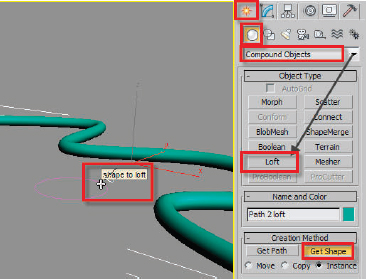
FIG 16.6
41. Select the object called “Path 2 loft”.
Note
The rendering of this spline is on for easy selection.
42. Go to the Modify Panel and turn off Enable in Renderer and Viewport. You will find these in the Rendering Panel of the object.
43. With it still selected, switch to the Create Panel.
44. Choose Geometry and the change the drop-down menu from Standard Primitive to Compound Objects.
45. Choose Loft and select Get Shape in the Creation Method Panel.
46. Select the “shape to loft” circle and then turn off Get Shape.
47. Switch to the Modify Panel so that you have access to the Deformation Panels at the bottom of the Modify Panel.
48. Choose the Scale Tool.
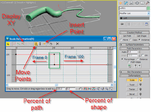
FIG 16.7
Refer to Fig. 16.6 for the icon intensive operation below.
49. Turn on Display XY axis (red and green crossed icon).
50. Click Insert Control Point (red line with yellow star).
51. Add two vertices.
52. Choose Move Control Points (looks like Move Transform icon).
53. Click the third point and zero out the shape percentage number. Set the position to 50%.
54. Click the second point and give its position 50% the scale value 100%.
55. Select the fourth point and give it a zero shape value.
Note
We are creating this step of two control points at frame 50 so that you can easily select them for animating to the end of the path at frame 100 and then back to frame 0 without grabbing the control points at either end of the path percent.
56. Go to frame 100.
57. Turn on Auto Key.
58. Slide the center two keys to the right. (There is a flyout for the move control to limit to one axis.)
59. Move the Time Slider to frame 0.
60. Slide the two keys to the far left.
61. Turn off Auto Key.
62. Scrub the Time Slider and you will notice the object disappears over time.
63. Save the file incrementally. I’ve saved it at this point with a file called chpt_17_visibility_04.max just in case you missed a step and want to examine my file.
I actually used this in an animation for one of my colleagues to demonstrate the trajectory of a fixed point on a rolling wheel. For his students studying calculus, it was difficult for them to visualize what this path would actually look like, much less to draw it accurately on dry erase board. In the Motion Panel, in the trajectory area, you can actually create a spline from an object’s trajectory. That’s how I create this animation.
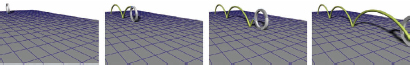
FIG 16.8
Growing an Object over Time with an Animated Extrude
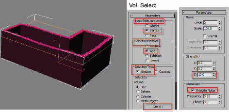
FIG 16.9
This one is similar to what we did with the torus but uses an Extrude Modifier. You could also build a wall with a slice, but it is worth learning this method to give you more flexibility and things to try. After demonstrating this in my class recently, we added a Volume Select Modifier and animated the top edge so that it ungulates as it grows. Animating modifiers can really breathe some life into your work. The Noise Modifier has a parameter for animating the effect based on frequency and phase, much as you would see in a number of space warps. Actually, noise can work in object space level as a modifier or in world space level as a space warp.
64. Select the spline object called “Line02” and add an Extrude Modifier.
65. Make sure your tangent control is set to linear.
66. Go to frame 50 and turn on the Auto Key.
67. Increase the amount spinner to 120 units and turn off the Auto Key.
68. Go to frame 0, switch to the top viewport and create a box about the size as the outline for the spline.
69. Note that my values were Length 220, Width 350, and Height 15.
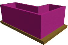
FIG 16.10
70. Hit the “F3” Key to enable wire frame shading.
71. Go to frame 50, enable the Auto Key and move the box up on the “Z” axis so the top edge intersects the top of the wall that has extruded over 50 frames.
72. Turn off Auto Key. Check from the front viewport that the box intersects the top of the wall from at least frames 30–50. See Fig 16.11. The box will be used to make a moving selection of the top of the wall.
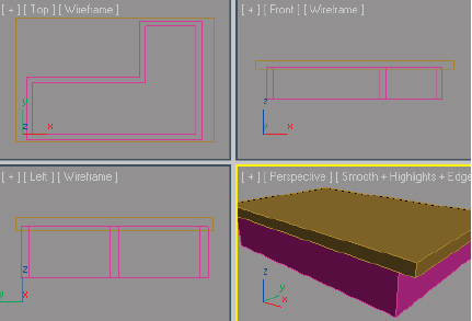
FIG 16.11

FIG 16.12
73. Select the object called line02 (extruding wall).
74. Change to the top viewport and go into the sub-object segment level of the line in the Modify Panel.
75. Select all the segments, pan down the Modify Panel, set the Divide number to “5”, and hit the Divide button.
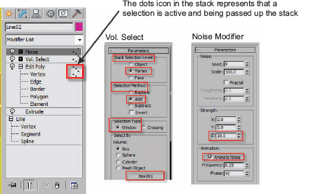
FIG 16.13
76. Turn off sub-object. Switch to the front viewport and add an Edit Poly Modifier.
We need to add the Edit Poly Modifier in order to get out the Vertex Sub-object components of this wall object. Note from Fig. 16.13 that there are dots next to the Sub-object Vertex level. This represents that a selection has been made at that level and left open to be passed to the Vol. Select Modifier above. The Vol. Select Modifier allows us to make a choice of what will be selected based upon another object’s volume intersecting the object. Although we are maintaining the selection the whole time, you could animate a smaller object intersecting the wall intermittently to create the illusion that one is reacting to another. I will typically demonstrate this with a ball hitting a surface which also has a displace space warp and a Flex Modifier added to get some bounce back as one object hits another.
77. Go to the Vertex Sub-object level and choose the top row of vertices.
78. Add a Volume Select Modifier without turning off sub-object.
79. In the Vol. Select Modifier, enable Vertex in the Stack Selection Level.
80. Enable Add in the Selection Method area.
81. Click the None button in Select By and choose the animated box (Box001).
82. Add a Noise Modifier. Put a value of 10 in for the “Z” strength and turn on Animated Noise.
83. Select the box, right click it and hide selection, and play the animation. That is gnarly!
84. Incrementally save your file as chpt_17_visibility_05.max.
So far we have been looking at ways to physically affect the objects with various modeling and editing functions. The next one is similar to the loft but will use an animated material in order to make the cone disappear. I like to teach this one a step or two away from the loft example to reinforce the concept of animating the keys in a graph. In this case, we will animate the flags left and right in a gradient map. Refer to Fig. 16.14 for the next set of steps.
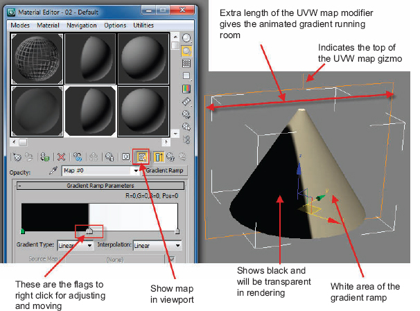
FIG 16.14
Animating a Gradient Ramp
85. Make sure Auto Key is off.
86. Select the cone and add a UVW map modifier.
87. Set the Alignment Axis to “Y”.
88. Set the Length to 60 units and the Width to 80 units. This will give your animation some running room.
89. Open Material Editor and make sure you are in Compact mode.
90. Assign another material to the object.
91. Add a gradient ramp to the opacity channel.
92. Turn on Show in the viewport.
93. Double click the center flag and turn it to pure black: 0, 0, 0.
94. Move your cursor near the white flag in the gradient area and drag a flag to near the center flag.
95. Do not overlap them.
96. Turn on the Auto Key.
97. Move the Time Slider to frame 100.
98. Move the center two flags to the right (do not overlap them).
99. Move the Time Slider to frame 0.
100. Move the flags to the left.
101. Turn off the Auto Key.
Hopefully these sets of exercises for controlling the visibility of your objects will give you a few good ideas for some areas of animating the properties of 3ds MAX, which you may not have been familiar with. There are other variations that you may want to explore as well. In post production, alpha channels, for example, can be used to hide and reveal layers of assets. You might want to consider adding Material IDs and Object IDs to your objects in order to select them for easier keying.