
CHAPTER 2
Working with Keys and the Dope Sheet
Richard Lapidus
Rule: Timing
After Completing This Chapter, You Will be Able To:
• Animate modifiers and limits.
• Create clones.
• Use the Set Key mode to jump to previously created keys.
• Scale and offset ranges of keys in the Track Editor.
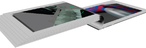
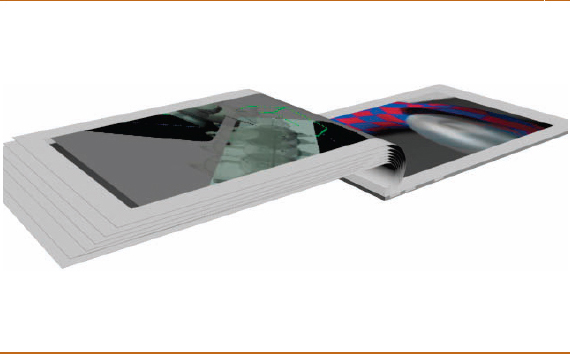
FIG 2.1
Although many of us don’t use animated flipping pages of a book in our projects, this is a very simple tutorial for getting your feet wet in the area of animated modifiers that can give your work a more natural and realistic motion. In addition, we will take our first exploration into the timing of motion and making it look more realistic. In a very subtle way, you will also hopefully see that there is an inherent overlap in the timing and even the rhythm of how things are animated as we saw in the previous chapter. Essentially when working on any kind of animation software, you will need to be able to control and adjust the length and speed of an animation segment. We will take a look at this concept through several of the chapters in this book.
I came up with the idea for this tutorial back in the early 90s based on a few problems that kept creeping up during some of my classes. Many of my students were flying a camera though their scenes to end up at a book with images of their drawing ports on the pages. Seemed like a nice idea, but the pages did not bend naturally or seem realistic in the timing of the flipping. Unfortunately, the idea caught on quickly, and most of them were turning stiff boxes, which didn’t represent how the pages in a book flip over. The subtle details of the mechanics involved in turning and bending a page eludes most people until they observe you doing it three to four times. It’s not really turning a page, but articulating the bend. The other half of the problem is that this is not a precisely timed mechanical motion. Mark your spot in the book and fan the text a few times. Every single time is different based on the amount of pressure applied with your fingers and the force of the bend.
After using this tutorial in classes for close to a decade, most of my students feel very comfortable with utilizing the Dope Sheet to enhance their animations. Think of the first keying or controls you use on your work as broad strokes of the animation and the adjustments you make in the Dope Sheet as a way to control the staging of the timing globally. The software does a great job in interpolating between key positions and doing the “tweening” of translating the object from one position to the next. One of our goals will be to take the exactness out of the equation and “dirty it up” a little bit. Realistically, although events can be displayed as timelines sequentially, there is overlap and variations in the duration of events. This is something we can control in the Dope Sheet very easily. Although you may not animate a book anytime soon, the ability to control time based on moving or scaling “sets” of keys is an invaluable skill set.

FIG 2.2
1. Create a box in the top viewport.
2. Go to the modify panel and change the parameters to:

Note
It’s safer to always make the parameter adjustments in the Modify Panel after creating the object. You can very easily create an object, deselect it, and then try to make changes to the parameters while still in the Create Panel, which will result in no changes to the object.
To get the page to bend later on, it needs enough complexity along the width. That’s why we are using 50 width segments. To add a picture or text to the page, three extra length segments will be added and adjusted, with a modifier to use a multisubject material in case you want to have a different material, like a picture in the center of the page.
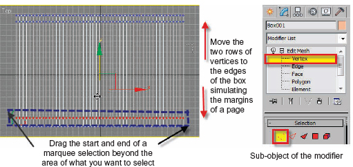
FIG 2.3
3. Add an Edit Mesh Modifier.
4. Go to the Sub-object Vertex.
5. Marquee select the top middle row of vertices.
I have added arrows to the diagram to show you where I click outside of the selection to start and finish the rectangular selection window.
6. Move the vertices up in the “Y” axis.
7. Select the other row and move it down.
8. Turn off the sub-object when you have finished moving the vertices.
Note
To turn off the sub-object of the modifier, you must click where you see yellow in the modifier stack. See Fig. 2.3.
When you have finished the next step, your box should look like the image in Fig. 2.3.
The Length Segs of 3 gives you two extra rows of vertices. To add the Multi/Sub-object material easily, the box is now set up with a center region having low complexity to select and change the Material IDs at the polygon level in a few steps.
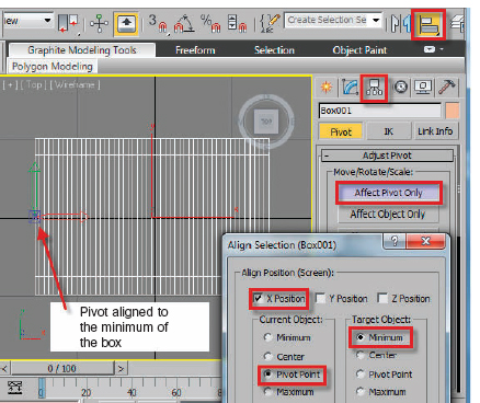
FIG 2.4
9. Open the Material Editor (“M” Key) and assign a MultiSub-object Material to the box. Make sure the sub-object is off when you assign the material. Set the number of ID Materials to 3 with three different colors.
10. Name the materials as well.
Note
When assigning sub-object IDs, it helps to use basic colors, so you can see if you have the assignment right. I also like naming the material, so I can remember which one goes where. Try not to use the color red, because sub-object selections are red and you may get confused.
We won’t be assigning images into the material in this chapter, but it was a good place to introduce the concept that 3ds MAX is inherently a numeric-based software program. Even though we are working with a graphic user interface that can let you see materials, lights, and shadows in real time, it is all driven by some pretty sophisticated number crunching. It’s all numbers. There are numerous opportunities to enhance the workflow when you recognize that the program not only animates by XYZ transform numbers but also records and controls data in other ways as well. We will look more in depth into the Material Editor in the Visibility chapter.
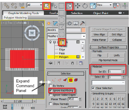
FIG 2.5
Refer to Fig. 2.5 for assigning the material IDs in the following steps. By default, all primitive objects created will have a material ID number of 1. For this project, the 1 will be the border, the 2 the front insert area, and 3 the back side.
11. Expand the Command Panel and go into sub-object Polygon.
12. Turn on Ignore Backfacing.
13. Change the Selection mode to Paint Selection Region and drag a selection as you see in Fig. 2.5.
14. Scroll the right part of the command panel to Surface properties.
Note
You can also right click a grey area of the Command Panel and choose Surface properties to get there quickly.
15. If the Set ID number indicates the number 1, then the object by default has a one assigned. If not, you will need to assign the number 1 to all the polygons and then change front center polygons where a picture would be the number 2. The name selection should show front picture as soon as you change the Set ID to 2.
16. Change to a bottom viewport or arc, rotate your view to the backside of the box, and select the same middle section of the box like you did for the top.
17. Change the Set ID to 3.
18. Turn off the sub-object and hit the “T” Key to return your view to a top viewport.
First, we want to change the pivot of the object before adding the Bend Modifier. In this situation where the page would be anchored at the left side like a page in a book, the axis of a bend and the pivot should be aligned here. Unlike traditional animation where the objects have no pivot and the motion is controlled by the person compositing the layers, all objects in the 3d world have pivots you must deal with. I like setting the pivot on an object like this before adding the Bend Modifier because the axis of the Bend Modifier will be set to the object’s pivot. Inherently, with most primitive objects, the axis is centered in the middle of the base with the “Z” axis running perpendicular through it relative to the construction plane. Say that five times fast and just remember the pivots aren’t always where you want them to be. See Fig. 2.6 for the next steps.
We are going to move the pivot before adding the Bend Modifier. Some modifiers like bend and lathe have centers that align to the pivot of the modifier to the pivot of the object. If you skip this step, the book will bend in the middle and you would have to go to the sub-object center of the modifier and adjust it.
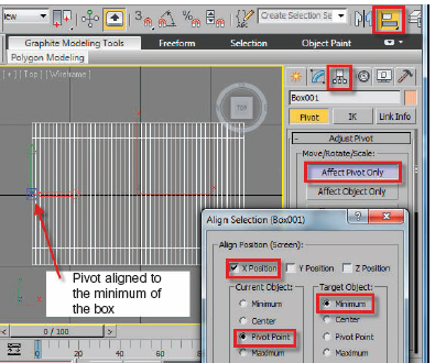
FIG 2.6
19. Go to the Hierarchy Panel and enable Affect Pivot Only. The Hierarchy Panel is the third tab in the Command Panel. This is the area adjustments and control over linked objects can be easily controlled.
20. Click the Align button in the Main tool bar and then click on the edge of the box.
21. When the Align Selection Dialog appears, enable X Position and set the current object to Pivot Point and Target object to Minimum.
22. Click Ok to exit the Dialog box.
23. Go to the Hierarchy Panel and turn off the Affect Pivot button.
24. Add a Bend Modifier.

FIG 2.7
25. Drag the angle spinner and notice how the object is skewing.
26. Return the angle to 0.
27. Change the axis to “X”.
28. Turn on upper and lower limits.
29. Increase the upper and lower limit to:
(a) Upper limit: 330
(b) Lower limit: −21
The limits help to control the areas of the modifiers affect on the object. Anything inside the limits gets the effect. When a modifier is added to an object, the amber gizmo that represents the modifier surrounds the extent of the object(s). To make the motion more realistic as the focus of the bend over time is changed, you will give yourself a little “running room” by pushing the limits out beyond the extent of the object. In addition to widening the area of the bend area, the timing is buffered a small amount because it takes a few frames for the limits to start moving in. Effectively, you will be falling off the force of the bend over time. We will animate the limits to a smaller amount over time as well as adjusting the Bend Angle. This will give your page a natural feel of compressing the area of the force over time.
30. The Bend Angle in Fig. 2.7 has a negative angle shown. Make sure you zero this out before going starting to animate the Bend Modifier. This was only shown for display purposes of the limits, Bend Axis, and checking the angle.
31. Turn on the Animate or Auto Key button.
32. Move to frame 10.
33. Increase the angle to −240.
34. Change the upper limit to 260.
35. Change the lower limit to −11.
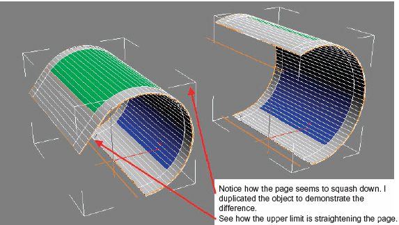
FIG 2.8
Your page should look like the image on the left side of Fig. 2.8. Even though the angle and limits are keyed together at the same frame, there is still an overlapping of the motion because the limits are moving in. As we saw in Chapter 1, I mentioned that you want overlapping of actions to create more realistic motion. There are traps to overkeying your work, so this is a nice way to missmatch the timing of the two changes but keep the keys at the same point in time. You will see later in the tutorial when the object is cloned that fewer keys are better.
36. Move to frame 15.
37. Decrease the angle to −200.
38. Change the upper limit to 129.
39. Change the lower limit to −4.

FIG 2.9
Scrub the timeline back and forth a few times. You will see a bit of a whipping motion start to appear in the bend. As you add more keys, this will accentuate a bit more.
40. Move to frame 20.
41. Set the angle to −180.
42. Set the upper limit to 35.
43. Set the lower limit to 0.
Notice how the page flattens as it reaches frame 40. This is impossible to do without the limits being animated unless you go to a more sophisticated selection of the volume. We will cover that in a later chapter. For now, let’s take a look at duplicating the pages and then offset the keys in a more natural fashion. The next few steps will be to create some copies and offset the timing. Pick up a book for a moment and fan the pages. They do not all flutter by evenly over time. Your thumb pressure changes, and there are moments when a page is caught.
44. Go to the front viewport.
45. Turn off the Auto Key and go back to frame 0.
The page is currently 1-unit thick. Before moving on, you could click down in the modifier stack to the box level and make it much thinner. For the purpose of demonstration, I will keep these objects a little thick, so it is easier to see what we are trying to accomplish.
46. Enable the Move Transform, hold the Shift Key and move the book down on the “Y” axis about −2 to −3 units.
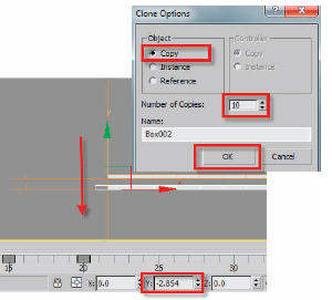
FIG 2.10
Note
You can “eye it” in the viewport or use the status line. You want to have enough distance, so the objects can easily be selected later for adjusting the keys.
47. When the Clone Options Dialog appears, choose Copy and 10 for the Number of Clones.
Note
I’ll post a short exercise on the website (www.tradigital3dsmax.com), which I use in my classes for demonstrating and recognizing visually in the modifier stack the differences between the three options. We want to use copies that will duplicate all the current animation, but keep them independent. If you choose Instance or Reference by mistake, the objects will be wired together. Basically if you make changes to one, they all will change to a certain extent. If you did choose Instance for example, merely go into the Modify Panel with it selected and right click the Bend Modifier. When the options appear, choose “Make Unique”. This will “un-wire” the objects, and the modifiers will operate independently.
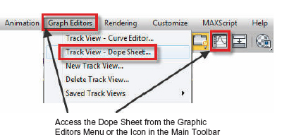
FIG 2.11
There are several key points about the defaults that I would like to mention here. Newer user’s to the program often get lost because of some of the default settings that are very subtle. If you use the ICON to access the Track View, the default one that appears is the Curve Editor. This version of the Track View displays the keys and trajectories. The other version, the Dope Sheet, will show your keyframes as squares or range bars. You will need to use the MODES Menu in the Curve Editor to switch to the Dope Sheet for this project. The next thing to be aware of is that only “Selected Objects” appear in the editors unless you turn this option off in the Display Menu: Filters Dialog in the Show Only Area. When you created clones with the Shift + Move technique, only the last object, box10, will show unless you turn off this option or select all the objects. Look at it, but leave it at the default for now.
48. Drag a Marquee through all of the box objects or hit the “H” Key to use the Select by Name dialog to select all the objects.
49. Click the Curve Editor icon in the main tool bar or Track View—Dope Sheet from the Graphic Editors Menu.
50. If you choose the icon to access the Curve Editors, it will default to Curve Editor. Simply change the Mode from Curve Editor to Dope Sheet.
51. In the Dope Sheet, activate the Edit Ranges Icon. See Fig. 2.12 for the location.
The goal is to scale and move the ranges of the keyframes to get a more random animated sequence. Figure 2.12 shows what your animation may look like after you have scaled some of the ranges longer and shorter. There are a few rules to follow to get this right:
• Don’t move the Top bar directly across from Objects. This will move everything.
• In this case, the objects are incrementally named in the order they were created with a negative “Z” offset. Box001 is on the top and Box002 is directly below it. It follows that no object lower can have its range finish before the one above it. If it does, it will certainly intersect.
• The length of the range bar determines the speed of the keyframes.
• Any bars that extend beyond the light grey area of the default active time segment are still there. You will need to enter the Time Configuration to show a longer active segment or hold the CTL + ALT Keys while dragging with the right mouse button to show more time.
• Dragging in the middle of a range bar moves it. When moving a range bar, the cursor will appear as a double arrow. Dragging either end when you see a single arrow scales it.
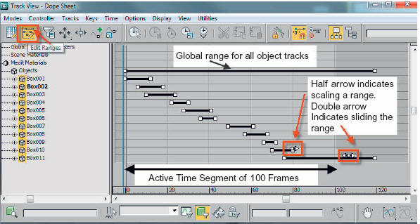
FIG 2.12
Note
The image above already shows the staggered range bars for the animated boxes.
Dragging in the middle of a bar moves it. Dragging on either end scales the sets of keys up or down. Basically evenly spread the animation over time.
52. Enable range bars.
53. Use the zoom extents to bring up all the frames.
54. Adjust and move the range bars.
55. Close the dialog when you are finished and play the animation.
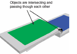
FIG 2.13
Noticed anything funny? The objects are intersecting and dipping through each other as they bend. This is not a big deal to fix and will give us an opportunity to utilize a useful feature near the play buttons. The Key Toggle mode will switch the next and previous frame playback buttons to the next key icons. This will let us snap between previously created keys to make adjustments to existing ones without creating additional keys. Too many keys in close proximity can lead to a lot of overexaggerated motion. Not a bad thing when you want to add exaggeration, unfortunately it causes problems when you least expect it.
56. Turn on the Key Toggle mode.
57. Select the second box and then click the Next Key icon until you see which key is the culprit. Verify that it is not intersecting the first box.
58. Repeat step 57 until you turn on the animate button back, select BOX02, and try to adjust the setting, so the second page does not intersect the first.
59. Notice how the Next Frame button changes to a Next Key button.
Note
This is helpful in letting you toggle to previously created keys to change them without adding new keys by accident.
60. Toggle to the last key on Box02. I changed my upper limit to about 42 or 43.
61. Repeat this for all the following pages.
As we explore timing and motion through this book, I want you to start developing a sense of the inherent inexactness of how living things move and react in the world. Typically, the rule is that living things move on curves, while mechanical devices tend to be more linear. Think of your software as a very precise mechanical device, except when it crashes of course.
62. Create a camera and position it similar to the placement in Fig. 2.1.
It doesn’t have to be exact, just try and get a nice close-up of the book while clipping at least one of the edges. Look for a strong diagonal through your composition. Also try adding a few other objects. At this stage of the game, I want you to just practice creating and maneuvering your camera for right now. Most of the books out there don’t focus on the camera work until the last few chapters. You may be wearing several hats including that of cinematographer. Do a search on the Internet for rules of 3rds, composition, and photography as a starting point if you have never taken a course in photography. It takes a while to develop the fine art of viewer immersion in a scene. You may even want to pull your favorite DVD off the rack and look at the making of the movie including the directors’ point of view.
63. Go to the Tools Menu, choose Grab Viewport, and drag across to Create Animated Sequence File.
This file is a temporary movie file created in the C:Userslogin_name Documents3dsMaxpreviews folder. There is also a command for renaming these temporary files (overwritten every time you make a new preview) in the same ToolsGrab Viewport Drag across area. To save time before rendering, we will often make previews from the different cameras in the scene and use a compositing program to slice these together. To get a feel for how the camera is working with capturing the action in a scene, it makes sense to take a step back and preview your work to check the flow.