
CHAPTER 10
Deforming Objects with Bones—Skinning, Envelopes, and Vertex Weighting
Chris Tedin
Rule: Appeal
After Completing This Chapter, You Will be Able To:
• Place bones into mesh models appropriately for deformation.
• Set envelopes with Skin Modifier and adjust falloff.
• Adjust individual vertex weights using the Weight Editor.
• Use more advanced deformers to create creases and bulges.
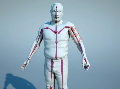
The best way to understand the technique of deforming meshes using bones by enveloping, or “skinning” as it is called in 3ds MAX, is to look at our own bones that lie under our own muscles, tendons, and flesh. Our skin can’t move without muscles, and both would simply collapse without the support and structure of the underlying bones. It is important to carefully study nature for inspiration and guidance while creating any animation rig. Every animal on the planet evolved by the demands of nature, and the stresses put on it by the struggle to survive. Whether built for speed, strength, flight, or underwater life, each animal has a unique structure that gives it mobility. There are patterns and similarities between many species, as well as subtle differences. Muscles grow for different purposes, growing leaner or more massive, lighter or denser. Each animal’s overall shape is determined by the interplay between all of these different variables and environmental conditions.
This chapter will introduce the concept of mesh deformation through the use of “enveloping” or “skinning.” Each vertex on the target mesh is pulled in different directions by “bones”, linked together in an animation “rig.” Skinning is a very popular technique for animating meshes in 3d and is used for feature films, commercials, and game production. It is a very robust system, allowing for a great deal of flexibility by bending the character’s limbs, as well as more subtle chest expansion, and facial deformations. Combined with careful “morphing” style deformations, skinning is a powerful tool in a 3d artist’s toolkit.
We will begin this chapter by creating a basic set of bones in a mesh object, in this case a human leg, and use 3ds MAX’s “skin” modifier to deform the mesh. The first steps will be to set up and adjust the basic envelopes that “capture” the vertices. These envelopes have falloffs, which allow the artist to smooth out or add creases between the bones. The next steps will go through the “Weight Table,” and show how each vertex’s weight can be adjusted to follow each bone’s influence differently. Finally, we will add a few simple Bulge and Joint Angle Deformers, which will give the character some more subtlety and realism.
The best way to understand skinning is to simply begin the process and work through the techniques step-by-step. I have a sample scene called “Leg_Skinning_Exercise.max”, which has the basic mesh (a human leg) and a few simple bones. It is best to begin with a low-polygon mesh to learn the techniques. In fact, it is always best to skin with as few polygons as possible. When the mesh becomes too “heavy” or dense with polygons, the process of adjusting the weight of each vertex becomes more difficult.
This is a typical bone deformation setup. The human leg with three basic bones set inside the mesh. Notice how the bones are placed within the “skin” of the mesh, simulating fairly accurately the actual placement of the leg bones. In some areas, such as the knee, the bones are fairly close to the skin. In other areas, the bone is set much deeper beneath muscle, fat, and skin tissue. Also notice that the foot pivots at the ankle rather than the heel, which is why the bone is set above the ground plane in that joint. Please feel free to use your own models with this exercise but be careful that your mesh density is rather low for this beginning exercise, especially when we dig deeper into the Weight Table.
1. Select the leg’s mesh. Go to the Modifier Panel and add a “skin” modifier to this mesh.
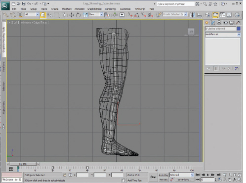
FIG 10.1
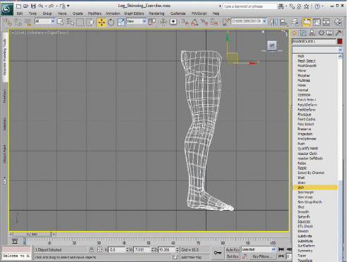
FIG 10.2
2. Click “Bones: Add” button and select all bones in the scene.
It is a good practice to have a proper naming convention for your bone objects. Even non-bone deforming objects should have the name “bone” added to the first part of their name, so that they can be easily selected in this Dialog box.

FIG 10.3
3. Slide the animation timeline forward to frame 40. I animated the calf and foot bones to preview the deformations on the mesh.
Hint
This is a great technique for showing problems in the deformation. Rather than deselecting the mesh and moving the bones, which takes time, sliding the timeline takes just a few seconds and never takes you away from the Skin Modifier Panel.
Notice that, with the default deformations, there are some problems with the deformation around the back of the knee and ankle.
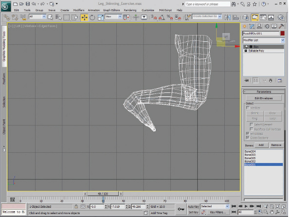
FIG 10.4
We will fix these problem areas with a few techniques, namely envelope adjustment and vertex weighting. I will also introduce the more advanced Joint Deformer as well. It is a good practice to save iterations of your files, so click “Save As” and press the “+” button next to the “Save” button to save an incremental version of the file.
4. The Envelope Adjustment tool is available by clicking the “Edit Envelope” button or by clicking the Envelope Sub-Object. Make sure both the “Envelopes” and “Cross Sections” boxes are checked.
5. Zoom into the top of the main bone, near the hip. Select “Bone 1” in the Bone List Panel. A sausage-shaped “gizmo” appears, which you can use to adjust each bone’s influence on the surrounding vertices. Select one of the handles at the top right, linked with a dark red half circle and vertical lines. As you pull this handle (shown in figure below), the colors on the vertices change from blue to yellow, orange, then finally red. Each color represents that bone’s influence on that vertex. Red is 100% and will allow that bone to move those vertices exclusively.
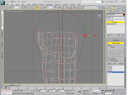
FIG 10.5
6. Pan down near the knee and adjust the bottom part of the envelope. Next, click on Bone 2, or calf bone in the skin modifier’s panel and adjust those envelopes as well. Notice how the half circle end of each envelope crosses over its neighbor. This region around each joint will share the weighting influence depending on its distance.

FIG 10.6
7. Test the deformation to see the results. You should notice a great deal of “softening” in the joint, which is an effect of a greater falloff distance. This might be suitable for softer regions, or a fish tail, but for a knee, it is a little too soft. We will adjust the inner envelope control to tighten it up a bit more.

FIG 10.7
8. Next, select the inner envelope control. This may require zooming in closely to see the control points. Expand this smaller “sausage” a little bit to increase the bone’s influence by shortening the falloff area to the next bone. Next, increase the inner envelope weight control on the thigh bone as well. The final result should look like this.
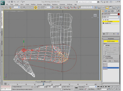
FIG 10.8
The effect is a bit sharper, but there are some problems around the inner part of the knee. This is a typical challenge for many animators, which is why you see many characters with tiny, tube-like legs. Thick, stocky bodies are much more difficult to skin without encountering this kind of overlapping problem. Clothing may cover up many of these problems, but these areas can be fixed with some creative vertex weighting.
9. Before we tackle vertex weights, let me show you one more feature with the envelope weights. If you notice, the envelope around the calf is just barely large enough to wrap around the main muscle. Select the Bone002_Calf. Scroll down the Modifier Panel to the Cross Sections and press the “Add” button. The cursor changes to a cross icon. Click midway up the thigh bone, and notice that a new cross section ring has been added. Click the “Add” button again to deactivate and adjust the radius. Notice how this ring changes size to encompass more of the calf muscle’s mesh.
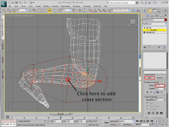
FIG 10.9
10. Now, onto the Vertex Weight Table! Click the Weight Table button. Intimidating, isn’t it?
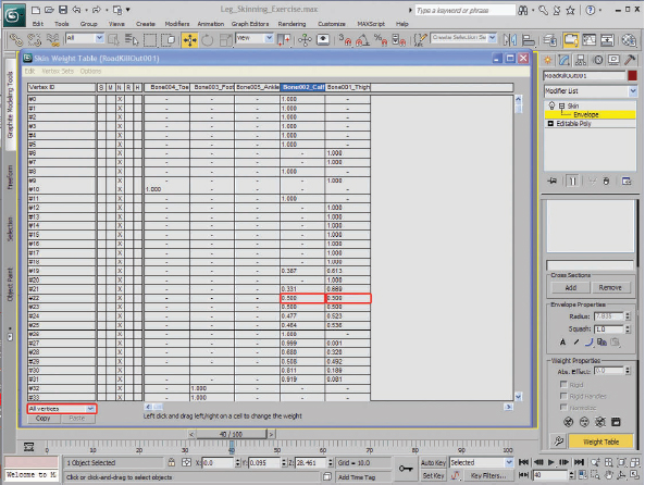
FIG 10.10
It’s not really as bad as it looks. All the vertices that are in the model are listed (by number) along the leftmost column. All the bones that are included in the skin modifier are along the top edge. Each vertex can be influenced by any bone in the modifier, and the amount is indicated where they intersect. For example, vertex #22 is influenced by Bone002_Calf by 50% (0.500) and by Bone001_Thigh by 50%. Therefore, this vertex will be equally deformed by both bones.
Now, let’s simplify the look of this Weight Table. Click on the rollout below the list of vertices and change it to “Selected Vertices.” Notice that there are no vertices showing in the Weight Table. That’s because there are no vertices selected. We will now begin selecting vertices and adjusting their weights manually.
11. Minimize the Weight Table, or move it out of the way of the model. We will begin selecting “loops” of vertices around the leg model and adjusting all of the values at the same time.
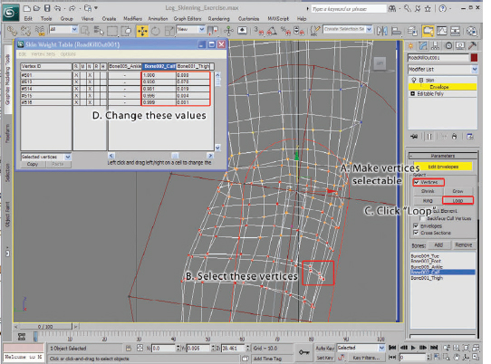
FIG 10.11
12. Click “Vertices” to make the model’s vertices selectable. Select a few vertices along a “loop” around the knee, just below the joint. Click the “Loop” button to select all the vertices around the leg. You can simply change the values in each column to adjust the weight influence by each bone. An easy way to do this is to use the “Absolute Effect” field.

FIG 10.12
You will notice that there are a few vertices in the selection that are not influenced by the thigh bone whatsoever.
13. To make a quick change, select the thigh bone in the Weight Table by selecting the top of the column. Then, type a small number, like 0.1 in the “Absolute Value” field. You will notice that all the vertices now share common weight values. It is important to type these values in the bone containing empty fields. If a field has a value of 0, making changes to the other field has no effect. “Normalizing” (where both fields’ values add up to 1) can only occur if there are 2 or more bones that influence that vertex’s deformation.
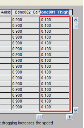
FIG 10.13
14. As you can see, the Weight Table is not as intimidating when you filter just the values you need to adjust. Often, it is easier to type the values in the “absolute” field and confirm the weights in the table. Although it is easy to tweak the values in the Weight Table as well. Simply click in the field and drag the mouse cursor from left to right to make small changes. The vertex will often move interactively while you drag, which is very convenient. This works best when the bone is set to an extreme pose, so the deformation will be visible.
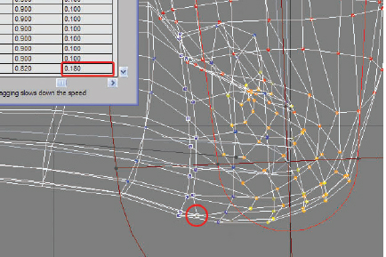
FIG 10.14
15. At this point, it is a general practice to begin to “blend” the weights from one bone to another, by increasing the influence of one bone over the other. Generally, at the joint location, the vertex weighting is 50/50, with equal weight on each bone. Working down the bone in this example, the weighting increasingly favors the calf bone, while working up the leg, the weighting favors the thigh bone.
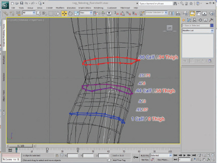
FIG 10.15
These values will, of course, vary with each project. Feel free to use the tweaking technique to begin fixing the problem areas around the inner part of the knee.
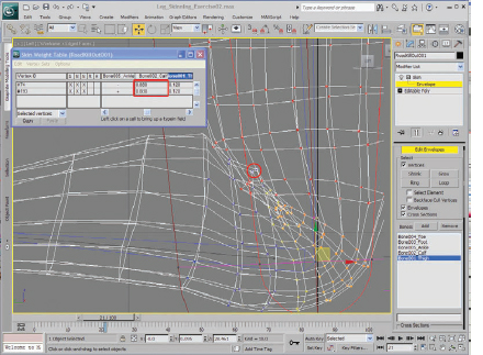
FIG 10.16
16. Select the vertices that intersect unnaturally and begin tweaking the values in the corresponding fields. By “scrubbing” the time slider from frame 0 to 20, you should be able to see the deformation and correct any problems. When completed, the final results should look something like shown in Fig. 10.17.
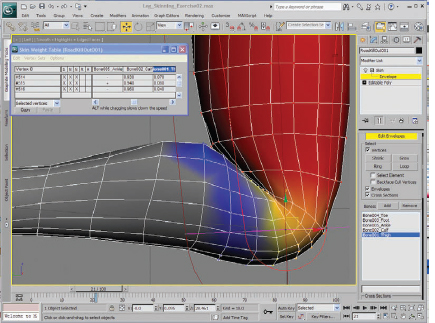
FIG 10.17
I turned on shaded view to see the results more clearly. Notice the nice crease in the back of the leg. All the intersecting vertices have been corrected by carefully tweaking the values of each vertex. This is why it is important to be economical when modeling any character you plan to skin. Inevitably, you will need to tweak these vertices. The fewer there are, the easier it will be to fix.
If you take a look at the Weight Table, you will notice that the total weighting for each vertex will always equal 1. This is called normalizing. The skin system will always level out any vertex’s weight to a total of 1, so that no excessive deformation will occur. Of course, you can turn this effect off by unchecking the vertex’s box in the “N” column.

FIG 10.18
Be careful, however. Unchecking this column while making adjustments could create some unexpected and unpleasant results.
Notice that there are now X’s in the “M” column on the left. This indicates that there was some manual weighting being done. If you wish to set the weighting to the default level created by the envelope tools, simply uncheck this column for each vertex you wish to reset to the default value.
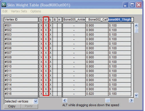
FIG 10.19
Typically, joints such as the knee or elbow tend to “deflate” and smooth out unnaturally with skinning alone. There are several tools in 3ds MAX to deal with this problem. The one I will be using is called the “Joint Angle Deformer.” The effects of this deformer are calculated after all the other deformers have been evaluated, so this is usually the last step in the process of skinning.
17. First, make sure that “Vertices” has been selected in the Skin Modify Panel. Then, select all the vertices around the knee. If you aren’t sure how many, go ahead and select a few more rows beyond the knee area. It’s generally better to select a bit more than you think you need. A good rule of thumb is about 1/3 the distance from the joint along the bone. Next, select the bone that will be used to “drive” the deformation. In this case, the calf bone. It is generally best to select it in the Bone Dialog Box in the Skin Modify Panel to avoid deselecting the vertices.
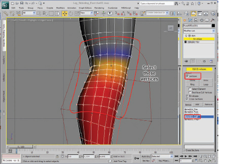
FIG 10.20
Next, expand the Skin Modify Panel by dragging its left edge to the left or scroll down and expand the “Gizmos” tab. Make sure that “Joint Angle Deformer” is selected in the rollout panel, then click the “+” button to add the deformer to the knee joint.
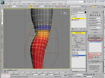
FIG 10.21
Scrub the timeline once again to see the result. You will notice a slight variation in the deformation shape. You can tweak the result in the next steps.
We will start to use this deformer to add some shape to the knee. Notice that the set of 20 control points on this deformer are red. As you bend the knee bone, the control points turn yellow. This shows that there are animation keys on these points.
Unlike time-based keys, which are linked to the timeline, these keys are based on the angle of the bone. These are commonly referred as “Set Driven Keys.” As you bend the deforming bones, the points turn yellow. You can set keys along any angle, but it is best to set keys at the most extreme angles, at least to start.
18. Scrub the timeline to frame 20 (or the most extreme angle for the calf bone). Turn on “Edit Lattice” and move the points near the knee outward to create a more realistic shape. The patella helps to retain the angular shape of the knee as it bends, and it is important to show this on a realistic character.
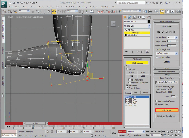
FIG 10.22
When you add move any point on the deforming lattice, all the points on the lattice turn red. This indicates that another key has been added. This one is at the most extreme angle of the Bone Deformer. Now, when you scrub the timeline, you notice that the points turn red at the most extreme angles, and in between, the points are yellow. Take care to only edit points during these extreme angles, so that you don’t inadvertently add more points in between these angles.
19. Scrub the timeline back to frame 20 and make sure the points are red again. Tweak the points at the back of the knee to reduce the intersecting meshes. Now, scrub the timeline again. Notice that the tweaks you make at frame 20 (more accurately, at this joint angle) have no effect on the other angle.
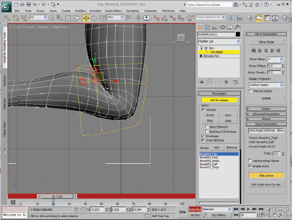
FIG 10.23
If you want to change the value, or at least view the Angle Keys, simply click on the “Edit Angle Keys Curves”. This shows the values of the keys during deformation.
Perhaps, the most useful feature of this panel is to see if there are any extra keys that might have been created inadvertently. You can simply remove those keys by selecting them and pressing the “Delete Point” button (the red X). You can also add some ease-in to each key by right clicking and selecting “Corner,” “Bezier-Smooth,” or “Bezier Corner,” as well as several other options.
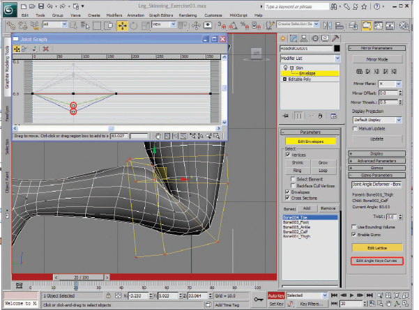
FIG 10.24
We are now finished with this exercise. Save your work with a new file name.
Now, let’s try one of the most useful tools in the Skin Panel, the “Mirror Mode”. Open the “Mirror_Mode.max” file. We will be working in Perspective mode during this exercise.
I have already added a bone system to this model, in this case a biped system. Technically, there is no difference between biped limbs and any other bone system in 3ds MAX. In fact, any linked objects can be used as bones, even geometry. I have also added the Skin Modifier to this mesh. Notice the problems around the arm when the timeline is scrubbed to frame 20. This is a typical problem for these areas, and using the Skin Weight Table is one of the best ways to solve it. Use the technique we used in the knee to fix the arm.
20. Select these vertices shown in figure below and the upper arm bone in the Skin Modifier Panel. Use the Abs. Effect Rollout to make these weighted entirely to the upper arm (1.0).
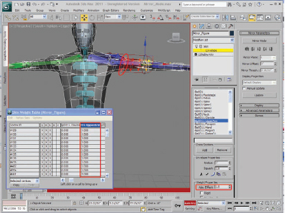
FIG 10.25
Scrub the timeline and notice how much better the arm looks.
21. Next, select the vertices one row closer to the shoulder and armpit. Change the weight to 0.5 in the Abs. Effect Rollout. Scrub the timeline and notice the improved effect. You might also want to tweak the vertex weighting of several other vertices under the arm or along the torso before mirroring the weight adjustments to the other side. It’s important to only adjust the weights on one side of the character. The Mirror mode will take care of the other half.
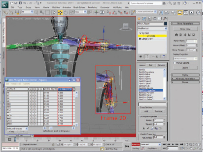
FIG 10.26
22. The next step is to mirror the envelopes. Click the “Mirror Mode” button. You will see all the vertices and bone indicators for the L Upper Arm appear in red. The mirror plane is colored orange and is located just to the right of the center of the figure.
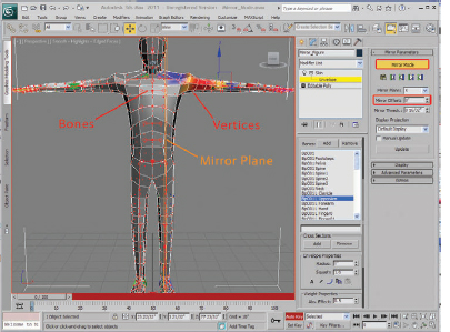
FIG 10.27
Adjust the Mirror Offset until the Mirror Plane is exactly in the center of the figure. You should switch to front view for accuracy. A setting of –4 1/2" should work. Notice that the Bone Indicators and Vertices turn from red to blue (on the character’s left) and green (on the right). Typically, 3ds MAX keeps this color scheme for character rigs. Notice that the Character Studio’s Biped rig also uses this color scheme.

FIG 10.28
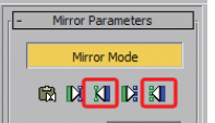
FIG 10.29
23. Now we will transfer all the weight adjustments from the left (blue) side to the right (green) side. It is customary to first transfer the envelopes, then the vertex weights. The buttons below the “Mirror Mode” button allow you to easily do this. Click the “Paste Blue to Green Bones” to transfer the envelopes from the left to the right side. The bones on the character’s left side turn yellow to indicate the operation performed correctly. Next, click “Paste Blue to Green Verts” to transfer the vertex weights. The vertices on the left side should also turn yellow.
When you scrub the timeline, you should see both arms deforming correctly. This technique is a big time saver, literally cutting your work into half for every character. Transferring vertex weights only works for symmetrical characters, however. You may get unexpected results if your character is lop-sided, or the vertex count and position is different for each side. Also, because Joint Angle Deformers don’t mirror, you would need to apply those deformers after the mirroring has been completed.
24. As a final touch, let’s add a “Bulge” Deformer to the arm. Select the vertices of the upper arm that you wish to include in the deformation. Next, select the bending bone that will “cause” the deformation. In this case, it is the L Forearm bone. Select the Bulge Angle Deformer and add “+” button to add the deformer.
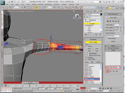
FIG 10.30
Just like the Joint Angle Deformer, you can add a key at the most extreme pose to shape the muscle. Scrub the timeline to frame 40, press the “Edit Lattice,” and move the control points to push the bicep into shape. Scrub the timeline from frame 30 to 40 to show the effect. Apply a TurboSmooth Modifier above the Skin Modifier to improve the effect.
The next skin deformer is quite flexible for many different challenging situations. It is called the “Morph Angle Deformer.” In a nutshell, it is a morph that is controlled by the angle of the bone. It is perfect for creating bulging muscles, as with the Bulge Angle Deformer, but more complicated deformations as well as simulating tendons. Setting it up requires a few more steps than the more basic Bulge and Angle Deformers but provides a few more options.
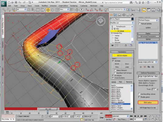
FIG 10.31
25. First, open up the file “Arm_Bulge_Start.max”. This file will work equally well for the Morph Angle Deformer. Add a “Skin Morph” Modifier to the stack above the “Skin” Modifier. Turn off the TurboSmooth Modifier if it helps to avoid confusion. Go to the Sub-Object mode, select the vertices around the upper arm. Next, click “Pick Bone,” and select the Forearm bone. This will become the bone that will drive the deformation. Click “Create Morph” button. This will set the first Morph key at angle 0.
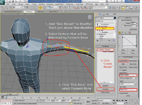
FIG 10.32
26. We have some animation for the forearm in this file. Scrub the animation to frame 40. The arm goes down, then up, and then bends at the elbow. This will be the next angle we will key. Click Create Morph in the Local Properties rollout. Name the new target “Morph Bent”.
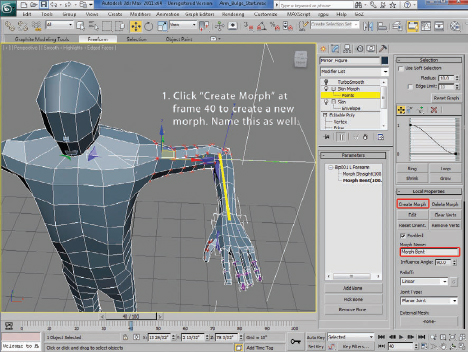
FIG 10.33
Next, click on the “Morph Bent,” or the second morph in the list, and click “Edit.” Move the vertices of the mesh to create a bulge shape in the arm, and a pointed elbow. Click "Edit" again to turn off edit mode. Scrub the animation back and forth to see the results. Turn on TurboSmooth again for the final effect. If you need to tweak the effect, simply scrub back to frame 40, click on the morp “Morph Bent,” click “Edit” and move the vertices some more. Deselect “Edit” and test it again.
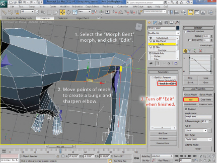
FIG 10.34
The Skin Morph is a very powerful deformer and extremely useful where most deformers will fail to give you the proper results. For the shoulder area, or the hips, you can change the “Joint Type” to “Ball Joint.” This is a bit more tricky, so try to use as few morphs to get the result you need.
27. Next, let’s wrap a shirt to the figure without resorting to using a cloth simulation system. If you are animating a figure with several different costumes, and the clothes are rather tight fitting, you can avoid the overhead of having to simulate the cloth simply by using the “Skin Wrap” modifier. Open the file “Skin_Wrap_Start.max”. You will see the same figure as we have been using, but with a shirt object. This was made simply by copying the body mesh, deleting the modifiers, then deleting the polygons around the hand, head, and lower torso. A “Push” Modifier was applied to create some distance between the body’s mesh and the shirt’s. The entire mesh was then collapsed into a Editable Poly object.
Select the off-white Shirt object. In the Modifier Panel, add the “Skin Wrap” modifier to it. Click the “Add” button, and select the body Polygonal object as the deforming mesh.
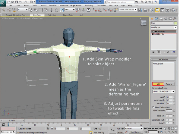
FIG 10.35
28. Adjust the parameters to tweak the final result. I found that increasing the falloff to 10 improved the results around the shoulder. You might also try an “Edit Poly” Modifier, selecting some vertices, then use a “Push” Modifier around the shoulders and areas where the body’s mesh is visible.
These are simple exercises using relatively low polygon models. As you improve your skills, you can begin to tackle much larger, denser meshes. More advanced animation artists and character riggers incorporate weight painting techniques and even complex muscle simulation systems to create more realistic effects for feature films and broadcast. As game engine technology becomes more sophisticated, these systems can be incorporated into those pipelines as well. There are virtually no limits to the levels of realism that an animator is able to achieve but starting with these simple techniques can often be extremely effective.