
CHAPTER 15
Tricks for Automating Motion and Controlling Timing
Richard Lapidus
Rule: Weight in motion
Rule: Timing
After Completing This Chapter, You Will be Able To:
• Create a link setup using multiple objects.
• Use a Link Constraint to weigh between multiple objects.
• Use an Attachment Constraint to have an object stick to another object’s surface.
• Link to world for free-form animation between links.
• Without linking, get the hands of a biped to move with another object.
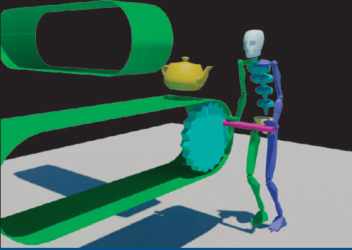
We want to create a complex linkage so that over time, an object can appear to smoothly move along two different surfaces. This tutorial will show you how to sync the movement of an object to basically follow two moving surfaces and also give you a segment of time to hand animate it. The objective is to have two different parent objects (dummies) that are attached to moving surfaces controlling the position of a teapot. Since an object can only be linked to one object at a time, or be a child to one parent in a hierarchy chain, a link constraint will allow us to get around this traditional limitation. Constraints are typically used to control one or more transforms of an object by giving up the “hand-keying” control to have the object animated by other more complex assemblies or motions. Although this is a very powerful tool, it is necessary to sometimes have the option of making adjustments by hand. This tutorial will show you how to assign control of an object’s transform and then also how to adjust it by hand when you want.
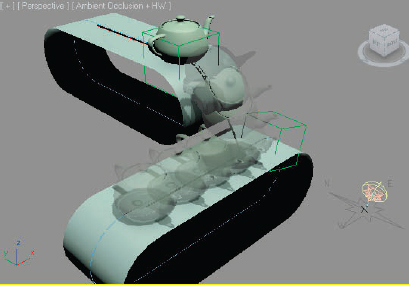
FIG 15.1
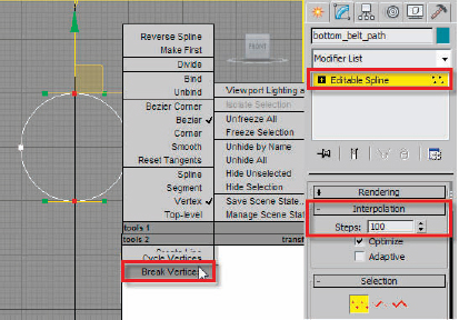
FIG 15.2
1. Reset 3ds MAX and enable the front viewport.
2. Go to Create Shapes and create a circle with about 100 radius.
3. Go to the Modify Panel and set the interpolation to 100 from the default of 6.
For splines that will be used as controllers for moving cameras, objects, or deformations, it is always best to use the highest interpolation value possible. There will be at least 600 steps along the whole length of the spline, which can be used for moving or deforming an object along the length. The default number of 6 will look smooth from a distance but will cause objects to have a lot of “jerky” stepping going around the curves. If you have ever tried one of the walk-through assistant tools that places the scene camera on a spline for a fly-through, you may have noticed that the camera snaps in a funny way through a curve. I’ve made a number of architects very happy in showing them how the default values of spline interpolation causes the problem with their fly-through animations.
4. With the circle still selected, right click the screen or the name of the object in the top of the Modify Panel and convert it to an editable spline.
5. Call this object “bottom_belt_path”.
6. Go to the Edit Menu and clone the object as a copy, call it “wheel_control”.
Whenever creating an object that I want to reuse again, I will typically incrementally save the file since I will be destroying the original or make a clone of it. This object will be used later on to create a fly wheel with crank to control the belts. We won’t be moving the pivot of the path object, so you could snap the new object back to the paths pivot. I like to plan ahead a few steps and avoid having a spinning object in this location that does not match up perfectly. You may want to use the technique covered in biped’s which constrained the feet to also constrain the hands.
7. Use the “H” Key or select by name and reselect the spline called “bottom_belt_path”.
8. Go to the Sub-object Vertex level, select both vertices in the center and then right click the screen. When the Quad Menu shows up, break the vertices.
9. Go to the Sub-object Spline level, select the right half of the circle, and then move it on the “X” axis about 500–600 units. This will be the path for our belt when completed.
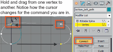
FIG 15.3
10. Go to the Sub-object vertex level, scroll the Modify Panel down, and choose connect.
11. Drag a line from the top left vertex of the left half circle to the top vertex of the other half.
12. Repeat this for the bottom so that the path is completely closed again.
13. Turn off Connect and then turn off the Vertex Sub-object level.
14. Using the Shift Key, move the path up in front viewport on the “Y” axis and leave some space between the two. Put in as much space as you like depending upon how much extra drop you want when an object moving off the top belt will fall onto the bottom belt.
15. When the Clone Options Dialog appears, make sure you choose clone and call it “top_belt_path”.
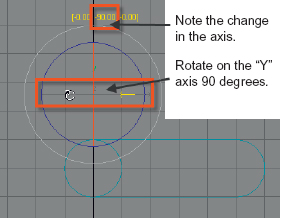
FIG 15.4
16. Hit “A” for angle snap and rotate the path 90° degrees on the “Y” axis. (This would be “Z” if you are in the perspective view.)
17. Change to the perspective view and pan or zoom extent the view.
18. Create a plane object that is about 160 units in length and by 800 units in width.
19. Call this object “top_belt”.
20. Go to the Modify Panel Drop-Down Menu and choose World Space Modifiers: Path Deform (WSM).
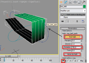
FIG 15.5
Make sure that you choose the one with a WSM after the name. There is also a Path Deform Modifier that works in Local Space on the Object, not World Space. The WSM works just like a space warp but between 3d objects. If you add the wrong one, delete it with the Delete icon in the modifier stack or right click and cut it. Chapter 14 goes extensively into working with the modifier stack and animating sub-object parameters. In my applied animation classes, we typically will work through the morphing exercise first to give a newer animator the opportunity to explore deforming objects more extensively.
21. Click the Pick Path button in the Parameters Panel of the modifier.
22. When it highlights, click on the top_belt_path. It will move to the path and look deformed.
23. Click the Move to Path button.
24. Choose “X” as the Path Deform Axis.
25. Set the Rotation to −90°.
26. Go to the Plane Level in the Modifier stack.
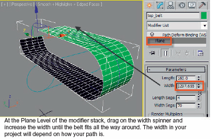
FIG 15.6
27. Drag the Length Spinner higher until the end of the plane meets.
28. Now increase the Width Segs to 60–70 so that the plane has more flexibility.
29. Increase the width to somewhere between 1300 and 1600, so that it wraps all the way around the path.
Depending upon your math skills, you could have easily figured out the length of the plane first to fit around this spline. Since there is some degree of variation in path lengths possible, I find it easy by just dragging the spinner and “eyeing it up.” The other possibility is to get it close and then adjust the stretch value at the Path Deform Binding (WSM) level.

FIG 15.7
30. Go to the Edit Menu and clone this object as a copy. Give it the name “lower_belt”.
31. Go to the Modify Panel and you will notice that the WSM Binding has cloned with the object including the assignment of the “top_belt_path”.
32. Click the Pick Path button and select the “bottom_belt_path”.
33. Click the Move to Path button so the plane is aligned to the lower path.
Orbit around your view and make sure an object that would be falling off the top belt could fall on the bottom belt. If you select the plane and the spline, they will both move together without distorting. See Fig. 15.8 for the relative location of the paths and planes.
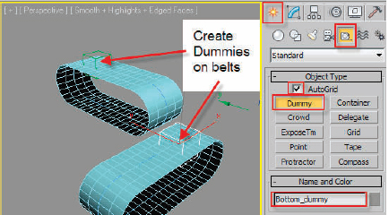
FIG 15.8
34. Go to the Create PanelHelpers and select Dummy.
35. Turn on Autogrid and create one on the top belt.
36. Call it Top_dummy.
37. Create another on the bottom belt. Call it Bottom_dummy.
38. Select the Top_dummy and go to the Animation Menu. Drag to Constraints and select Attachment Constraint.
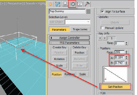
FIG 15.9
39. When the marquee line appears, click the top_belt object to assign it as the attachment.
40. You are sent into the Motion Panel. At frame 0, Click the Set Position button and then click and drag near the center of the belt at the far end as shown in the picture. Use the A and B position to fine tune. Turn off Set Position.
41. Select the Bottom_dummy. Add an Attachment Constraint to it as well. Check position from top viewport so the second dummy has a starting position far enough down the belt relative to the first.
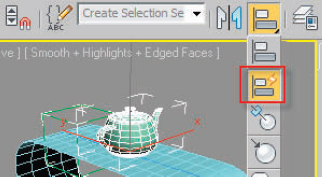
FIG 15.10
42. Create a teapot with the Autogrid on relative to the Top_dummy. Quick align it if you like.
43. Hold the CTL and Alt Key and drag with the right mouse button on the timeline to increase active viewable time to about 200 frames.
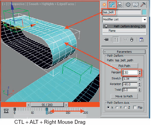
FIG 15.11
44. Select the top belt and go into the Modify Panel.
45. Turn on the Auto Key, move to frame 90 and adjust the percentage along path so the dummy moves across the top of the belt to a position of looking like it will fall off. I used about 32%. If your spline is reversed depending on how you connected it at the vertex level in a prior step, you may have to use 70%.
46. Select the bottom belt and go to frame 140. Click the percentage along the path spinner up and down one click.
47. Go to frame 200 and increase the path percent so the dummy moves across the belt to a precarious position. I used about −32%. If the object looks like it is moving the wrong way, try 120%.
48. Turn off the Auto Key.
49. Go to frame zero.
50. Select the teapot, go to the Animation Menu, and add a Link Constraint.
51. Click the Add Link button if it is not active and select the “top_dummy”.
52. Go to frame 90 and click Link to World.
53. Go to frame 140, click Add Link and select “bottom_dummy”.
54. Turn off Add Link.
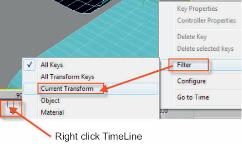
FIG 15.12
55. Right click the timeline, choose filter, and drag to current transform.
56. Turn on the Auto Key.
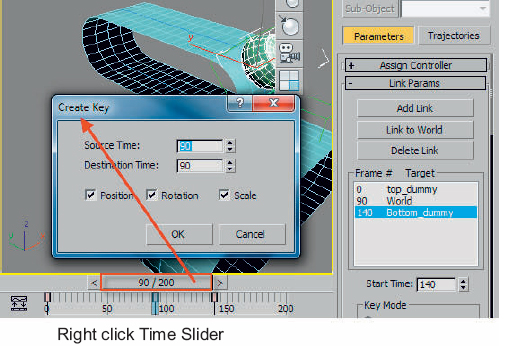
FIG 15.13
57. Go to frame 90 and right click the Time Slider. Set a position and rotation key.
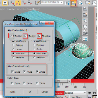
FIG 15.14
58. Go to frame 140. Select Align and then click the Bottom_dummy.
59. Make sure that X, Y, Z are all on, choose pivot to pivot, and then turn on X, Y, Z for Align Local.
60. Hit OK. Adjust rotation as needed.
61. Activate the left viewport.
62. Right click the teapot and turn on Trajectory in the Object Properties.
63. Drag the Time Slider between frames 90 and 140.
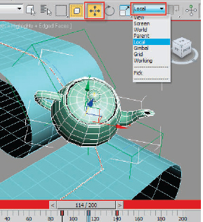
FIG 15.15
64. The teapot will appear to move through the top belt a little.
65. Turn on Select and Move, and change the Reference Coordinate System to Local.
66. Move the teapot away from the belts along the “Z” axis at around frame 110–112.
67. Play the animation.
68. Create a star spline with Radius 1: 95, Radius 2: 85, and 19 points. Call it “gear”.
69. Add an Extrude Modifier with an amount of about 25.
70. Align this object locally to the “wheel_control” spline.
71. Create a tube with the Autogrid on relative to the “gear”. Radius 1: 7, Radius 2: 8, and Height of about 150.
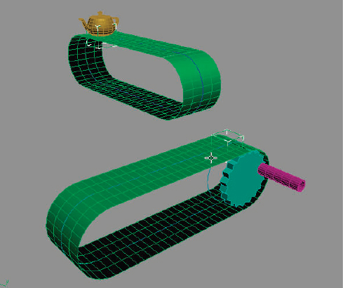
FIG 15.16
72. Add an Animation Link Constraint and choose the “gear” as the first link.
73. Right click the timeline and in filters, select object.
74. Select the “lower_belt” and the percentage keys of the Path Deform Binding (WSM) will appear on the timeline.
75. Marquee selects all the keys and when they turn white indicating the keys are selected, delete them.

FIG 15.17
76. Hit F9 and render your scene.
77. Select the belts and add a shell modifier to each.
You can see through the plane because these objects only render one side. There are a few ways to get around this. The object can be slightly modified by adding a shell modifier to give it some thickness. Without adding complexity or geometry, several different types of materials may be added. A standard material with two sides will work, but a double sided material that will put two different materials on the front and back would probably be more realistic.
If you haven’t saved in a while, this is a good time. Also do an edit hold in case the axis is wrong in the next step. We want to control the speed of the belt by the rotation of the turning of the gear. This is done with wiring. Think of wiring as what happened in a clone operation with instances except with more control. If you want to have a character walk up and attach his hands to the handle and move with the crank, this is a nice way to interactively control both.

FIG 15.18
78. Select the “lower_belt”, right click it, and choose Wiring from the Quad Menu.
79. Drag across from Space Warps to Path Deform Binding to Percentage along Path.
80. Once the parameter of the belt has been chosen, move the cursor over the “gear” and repeat the steps to choose the “Y” axis of the rotation.
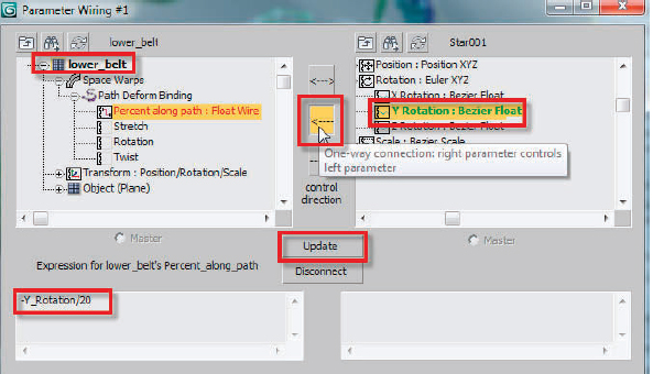
FIG 15.19
81. Select the direction arrow in the center to point from the controlling object toward the object you want to receive the control. Hit the Connect button. In Fig. 15.19, it says update. Once you have wired two parameters together and tested it, any changes need to be updated. In Fig. 15.19, the expression has changed to –Y_Rotation/20. I basically put the /20 to divide values of the degrees of rotation being passed to the percentage of the path by a much smaller number. If you don’t change it and update the value, it will move way too fast.
82. Select the “gear” and rotate it on the “Y” axis.
If you want to lock the rotation orientation just to the “Y” axis, you will have to lock it down in the Hierarchy Panel Link Info Section. I created my circle in the front viewport, which pointed the “Z” axis 90° from that view. When the gear was aligned to it, the “Z” axis of the object was aligned to the same orientation. In world space, the gear rotates on “Y” but its local orientation is “Z”. Unless the objects pivot is aligned to the world, the two won’t match up. As per Fig. 15.20, go lock the “X” and “Y” rotations.
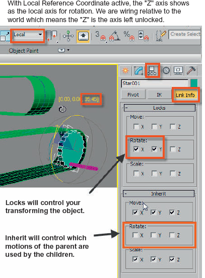
FIG 15.20
83. In the Locks Panel, turn on the “X” and “Y” locks for Rotate, leaving the “Z” axis available for it to be rotated by a character turning the wheel in its hands. This will allow you to rotate on just one axis as a spinning gear would normally turn.
84. In the Inherit Panel, turn off the X, Y, and Z Rotate check boxes.
85. Repeat the same steps for the Tube001 object.
By turning off the Inherit Rotate controls for the Tube001, it will move in space with the gear but not inherit the rotation. If you bind the hands of a biped to the tube, you would see that hands maintain the same orientation and revolve through the wrists. By turning off the Locks of the “Z” axis like you did with the gear, there is always the option of adding some rotation to the tube so that you can show some struggling of the biped to turn the wheel.
FIG 15.21
86. Create a biped about 600 units tall or what you think is a good relative height for your scene.
87. In the Name Selection box, create a set for the bip01 com object.
88. In the Motion Panel, go into Figure mode and rotate the biped 90° so it faces the crank as shown in Fig 15.21. Don’t worry about the pose at this point.
89. Turn off the Figure mode.

FIG 15.22
You want to position your biped so it is a little bent over and ready to turn the handle. By anchoring the feet, you can move the main parent of this rig, biped001, and have the feet stay in position. Otherwise the feet would move through the floor.
90. Select the feet and in the Keyframing Tools Panel, turn on Anchor Left and Right Leg.
91. Select the four spine objects and bend them to give the back some arch.
92. Move and rotate the hands so that they rest on the top of the crank.
93. Select the Bip001 com object and move it down slightly.
You want to position your biped so it is a little bent over and ready to turn the handle.
94. In the Key Info Panel, set a key.
95. Set another at around frame 135.
96. Go back to frame 0 and now we will get the hands to move with the rest of the crank.
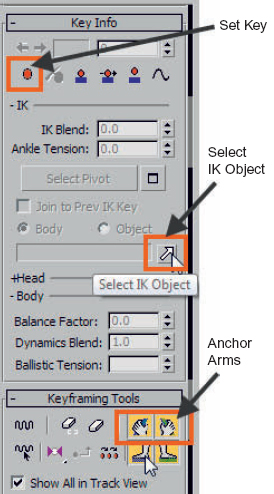
FIG 15.23
The next step is to have the hand move with the crank and get the arms moving inversely and will require using the Key Info and the Keyframing Tools Panel. We need to select the object to have the hands follow in the Key Info Panel and then anchor them in Keyframing Tools.
97. Select Left Hand which is blue and click the Select IK Object Arrow in Key Info as per Fig. 15.23.
98. Click on the Tube001 object.
99. Now click the Blue Anchor Arms Icon in the Keyframing Tools Panel. You will see that the name Tube001 appears as the target object in the naming field of the Select IK Object. The radio button that is set to body by default is set to object.
100. Repeat these steps for the right hand.
101. Scrub the timeline and notice how the hands will move for a certain number of frames and then the tube object will rotate out of reach.
102. To finish this project, simply scrub through time and add some extra bend keyframes to the spines and a little vertical and horizontal movement to the bip01 object.