
CHAPTER 4
Deforming Objects Based on Motion and Relative to Other Objects
Richard Lapidus
Rule: Weight in motion
Rule: Timing
After Completing This Chapter, You Will be Able To:
• Use World Space Modifiers and space warps.
• Link and bind to space warps.
• Create secondary motion using noise.
• Use path deformation.
When getting one object to interact with another, there are a variety of really basic tools that can be utilized to understand how the program works before using the more advanced features of the program. Many times, if you are not using the right axis, a pivot is off, or a single button is not enabled, the results may appear less than desirable. I call this the “it’s always one button” problem. During the teaching process of a project, I try to get feedback from students relative to what they see happen on the screen and the myriad of possible adjustments that could be made relative to what they know about how things are built and animated. In the early stages of learning this program, they are typically so overwhelmed by the number of buttons and parameters that they forget to reference how things really are in the real world. Animators typically will study motion through interaction, observation, or using some type of media. In the early years of 3d animation, it was not uncommon to use the photography of Eadweard Muybridge. Lately, the motion is captured with 3d suits, high speed cameras, or via video. This, of course, is a starting point. Once we start to imagine how something should act, the next step is to make it believable within the reality of its scene. That might entail exaggerating the motion or overlap of a variety of motions. With a study of motion, the animator must examine how things are built, ranges of motion, and the timing associated with the way real things move. Once we begin to understand that, then one of the goals is to show the intent. We will start by getting a tube to swallow a sphere. The first reference for developing this technique came from watching my son’s pet boa constrictor and then an exploration of the ways that the swallowing effect has been exaggerated. In the movies, we have seen at one point in time a character being swallowed by another. In the cartoons, I can remember one eating a stick of dynamite and watching the resulting explosion. Sometimes the character survives it and reacts to the action. In this tutorial, we will explore the exaggerated motion and timing of a large object moving through a small space. That can be a tricky thing to do with straightforward keying of transforms.

FIG 4.1
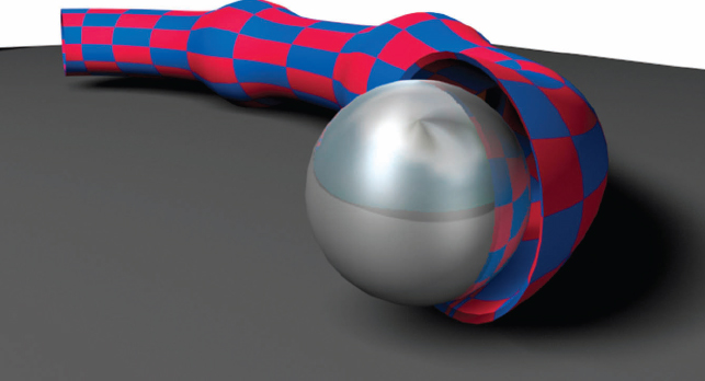
Our goal is to get a moving object to go through a curved tube and have it displace the tube as it moves through it. In addition, we will look at a few ways to make adjustments to the keyframes so that we can exaggerate the motion a bit. The tools we will be using are linking, path constraints, binding to space warps, and a look at the difference between World Space Modifiers and Local Modifiers. So as not to build a reference manual at the start of this chapter explaining all those interesting new words above, I’ll give you the explanation as they are used.

FIG 4.2
1. Make sure your unit setup under the Customize Menu is set to Generic Units.
2. Activate the top viewport and create a sphere with radius of 20 from the Standard Primitives portion of the Create Panel.
3. Create a tube with 15 and 18 radius and 300–425 height. Also increase the height segments to 45–50 and the number of sides to 30–35.
The variation of these numbers is to give more or less complexity to the tube, which will be deformed by a space warp moving through it. As I will demonstrate in later steps, the complexity can be changed or even animated if you like.
4. Create an ellipse of about 150 units in length and 350 in width from shape types.
5. Switch to the perspective view and click the name of the Smoothing type in the upper corner of the viewport so the Edge Faces mode can be enabled. The keyboard shortcut is F4.
6. Create a Displace Space Warp from space warps types (looks like a wavy icon). Drag out a small rectangle anywhere in the perspective view and right click to turn off Create mode.
Space warps include a wide range of helper objects that represent some type of force emitter or deflector. These are nonrenderable objects used to control a wide variety of parameters relative to the control you want over objects and particle systems. In Fig. 4.3, there are several things I want you to note that will affect the success of at least starting to use these in your scene. The first is the Strength and Decay values. By default, they are set to 0. Many new users to this program make the mistake of adding something like a modifier or space warp and then fail to adjust the valves. If something isn’t working, select the object and review it in the Modify Panel. Think of yourself as an auto mechanic going through a number of steps testing out the parts. Another noteworthy feature here is the ability to add bitmaps or maps in the Images section of the parameters. I’ve used this a lot to bulge, displace, or make subtle deformations to surfaces with maps to get scene objects looking more real world and less mechanically precise.

FIG 4.3
7. In the Modify Panel, change the type of gizmo from planar to spherical and give it dimensions of 25 x 25 x 25 so it is larger than the sphere.
By using even numbers, the dimensional size of the warp is even along all three axes into space. It will also project a force out into 3d space forever unless we control it. If you were to make one dimension longer, you might use that to emulate the effect of the swallowed object becoming squeezed and elongated. The outside radius of the tube is 18 units and the sphere is 20 units. We want to visually see the warp as it moves through the tube so that it is easier to recognize when it isisn’t affecting the tube. In later steps, we will control how far that force affects the tube when it is bound to the warp. Essentially, the size of the gizmo typically does not matter. It emits from the center and the extent is only important if you are using it to hit and react with another object.
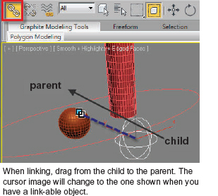
FIG 4.4
8. Using the Link Tool, drag from the edge of the Displace Space Warp to the sphere. This will link the Displace Warp to the sphere.
9. Choose the Select Tool or the Move Transform to turn off linking.
When the sphere is moved through the tube, it will pull the Displace Space Warp with it. You will notice as you dragged from the warp to the sphere, there was a dotted marquee line. This represents that a parentchild relationship was being created. Linking is a common process used in most animation processes involving a complex moving structure. If you hit the “H” Key on your keyboard, the Dialog that appears will show the Displace Warp is indented under the sphere. The warp will now be inheriting any transform for the sphere. As the sphere moves along a path in the next few steps, it will pull the warp with it.
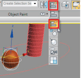
FIG 4.5
10. Quick align it to the sphere.
Note
You should acquaint yourself with the basic navigation of the interface and take some time to memorize the icons. This takes a little time, but I will copy extra images throughout the book of the most common ones for newer users.

FIG 4.6
11. Select the sphere and from the Animation Menu give it a path constraint.
12. When you move the mouse, a marquee line will appear that seems to be attached to the sphere.
13. Click on the ellipse to set it as the spheres path. The Motion Panel will automatically be active.
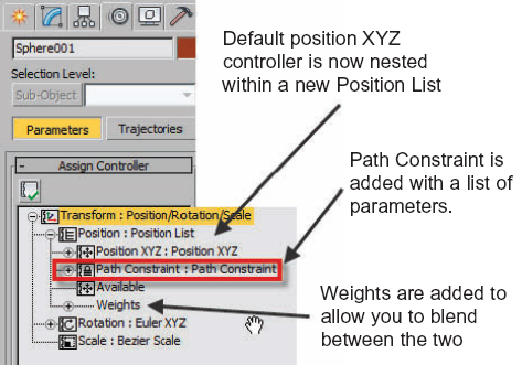
FIG 4.7
Take a moment to examine the Assign Controller Frame within the Motion Panel. All objects by default have different kinds of controllers added to the three transforms that may be changed at any time. If you ever add the wrong kind of controller, simply select the track, hit the Assign Controller button and replace it with one of the defaults. The Move Transform is shown as Position and has a Position XYZ controller as the default. By giving you three separate tracks, individual vectors can be animated or controlled individually. For example, you might want to add a little up and down bounce to your object as it moves through the scene. You could add Position List to the “Z” position track, put a noise float on the “Z” axis, and then blend the two. Even though you are giving up hand control of moving the sphere on a path, it is not entirely stuck there.
14. Change the path percent to −35 (negative). This will move the sphere to the middle portion of the front of the ellipse.
You may now notice that there are now two red squares on the timeline at frames 0 and 100. This represents 0% and 100% of the path. The sphere is on the far right side of the ellipse and will move counter clockwise around if you play the animation. The position or move transform is now controlled by a percentage of the ellipses path. The sphere can still be rotated and scaled, but not moved without some adjustment to the controllers.
If the path percent is changed in the Motion Panel with the Auto Key off, the percentages offset to still use 100% of the path. If an adjustment is made with the Auto Key enabled, a new key will be created. We will do this later on to simulate the tube swallowing the sphere.
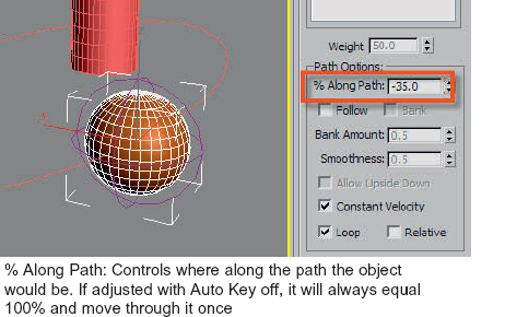
FIG 4.8
15. Select the tube and go to the Modify Panel.
16. From the Modifier Drop Down List, add a Path Deform (WSM) from the World Space Modifiers Category.
World Space Modifier: This WSM Path Deform is not the same as the regular Path Deform Modifier. WSM Modifiers allow an object to be modified by another object in space that is not a space warp. We will see later on that when the tube is bound to the Displace Space Warp, it looks the same in the modifier stack. Both can be deleted here, but objects are bound to warp with the Bind to Space Warp button in the Main toolbar.
17. Notice that the Path shows <None>. Click the Pick Path button and left click on the ellipse.
18. Hit the Move to Path button. If the object does not fit around the ellipse with “Z” axis … try the “X” axis or “Y” axis as needed.
Most of the time, the “Z” axis will be the right axis unless you created the object with an orientation that did not have that axis pointed up relative to the world. In this case, the tube was created in the perspective view that has the “Z” running up from the construction plane. The “Z” axis pointed perpendicular through the object. This may not always be the case, so it does need to be checked occasionally.

FIG 4.9
19. Click the Bind to Space Warp button (next to unlink) and drag to the space warp. Choose the Select Tool once again to turn off Bind to Warp.
20. Move to frame 50 or 70 so the ball is in the tube.
21. Hit the “H” Key on your keyboard to bring up the Select by Name Dialog. Choose the space warp and then go to the Modify Panel. Notice that the strength is set to 0; this is a default that has no effect. Slowly increase the strength by dragging on the spinner (double arrows) until the tube starts to bulge.
Notice that if you go too far the inside surface may push through the outside surface. You will also see that the ends of the tube are bulging off the path. To control the effect of the bulge out into space, you will need to turn on and use the Decay. Depending on where you are in the program, this term can be interchanged with fall-off. They are basically the same. It lets you control how far out into space the effect will go.
Hint
If you put too much of a value on a spinner, just right click it to zero it out.

FIG 4.10
22. Turn on the Decay and slowly move the value up. For the image in Fig. 4.10, an extra tube is displaced on the left with values too high. The one on the right uses 35 Strength and 2 Decay.
23. Play the animation.
Is this motion or animation? Disney defined the term of animation as to bring the illusion of life into a character. The ball is moving and the tube is bulging as it goes through it. Neither is alive and I don’t get the feeling that this is not a purely mechanical motion and adjustment. Thinking about the snake for example, it grabs the meal, usually bigger than the opening of the mouth and then slowly works it in. After sometime, it needs to move it through the beginning of the digestive track to a place … well … let’s not go into too much detail about that process. If you want the animation to appear to gulp, select the sphere, turn on the Auto Key and move to a frame where the ball is inside the tube. I will show you the fine art of adding the “gain some ground and lose some ground” keying process to show that there is some force at work to get this tube to eat the sphere. If you think about the two original path percent keys, those are the start and end of the path being used. Essentially, the sphere is being pulled into another position. If we think about this as a big rubber band, what would happen if we set another position where the sphere is in the tube and then set another key a few frames later with a lesser path percent value than the previous key? The sphere will move into the tube and then back up a bit before being pulled farther along.
24. Drag the time slider so the sphere is just inside the “mouth” of the tube.
25. Select the sphere, and turn on the Auto Key.
26. Go to the Motion Panel and click the path percent spinner up one click and then down one click.
Notice how the spinner now is bracketed with red corners. This indicates that a parameter has animation keys. Any numeric value in the program can virtually be interpolated. Think about it for a moment … color is numeric, so the colors, opacity, and a variety of other material attributes may also be animated.
27. Drag the time slider 5–10 frames farther in time.
28. Now drag the path percent spinner down until the ball is back outside the tube.
29. Play the animation.
30. Add about two to three more sets of keys and then save your project.
It appears that the sphere is moving into the tube and then coming back out before going farther into the tube. You get the idea now! Move through time and repeat this process. The goal is to have the sphere seem to get stuck and move at different rates of speed through the tube. For some secondary animation, you could also try animating the decay and strength of the Displace Space Warp. Let’s look at another way of seeing the motion, adjusting the keys, and even adding some random motion to the bulging of the tube as the sphere moves through it.
31. Make sure that the Displace Space Warp is selected and open the Mini-Curve Editor. It is located at the lower left corner of the interface. See Fig. 4.11. I typically will use the Track View Curve Editors instead of the smaller one because we have dual monitors in our classrooms and it is easy to move to the side. The Mini-Editor allows for quick access but does require some amount of panning once open.
The Curve Editor is where every parameter of the program can be displayed and adjusted. Think of it as the master control panel for your whole 3d world. Everything is accessible from the number of sides of an object to the maps and mapping coordinates on it. It is accessible in a few ways. With an object selected, you can right click the screen and the Quad Menu will appear with access to the Curve Editor. There is also an icon in your Main toolbar that looks like a graph. It is also located in the Graphic Editors Menu.
32. Since the Displace Space Warp is selected, it should be the only object to appear in the list on the right.
33. Hit the “+” next to the object name to expand the tree and see all of the object parameters.
34. Select the Strength parameter and then Assign Controller from the Controller Menu.
35. A list of controllers will display. Select Noise Float.
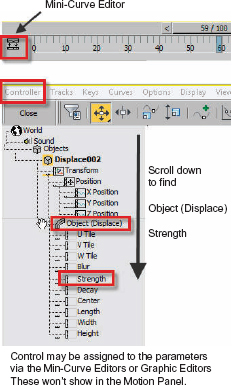
FIG 4.11
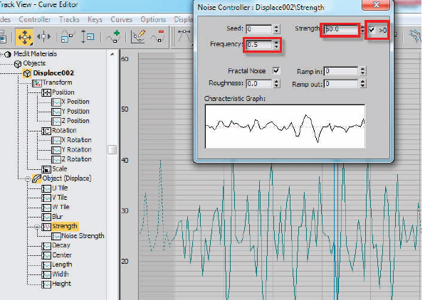
FIG 4.12
36. The Noise Float Controller Dialog will appear.
37. Check the button next to >0.
38. Increase the Strength to 50 and set the Frequency to 0.5.
39. Close the Dialog when you are done.
The controller will put a wave on the values of force, but we need to control it a bit. The strength of the Displace Warp was previously set to about 35. We want the side of the tube to be undulating so an amount greater than 35 should be apparent, but we don’t want too much. Somewhere around 50 should give us a distortion that is apparent. Using the greater than zero (>0) control will keep the values from going negative, which would show the ball through the tube. Looking at the graph of the values, you will see the strength is jumping around, but still falling low enough for the ball to show. Before fixing that, let us examine a few more parameters. The frequency will control the amount of repetition of the noise. As a side note, you will see this repeats in forever. The wave doesn’t stop and fit within the time frame. That can be controlled. Ramp in and out, which we are not using, will decrease or fall off the wave of the noise much like the Decay did for the space warp. Useful, but it won’t help here. We will need to bake the keys and move some of the values around.
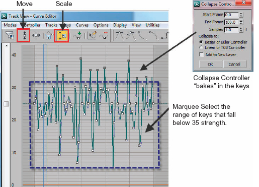
FIG 4.13
40. In the Curve Editor, make a Marquee selection of all the keys that fall below the original bulge level you selected in your project.
41. Use the Scale Key to squeeze these together vertically.
42. Move the keys so the bottom range is 35.
When played back, the numbers will cycle through in the Modifier Panel and you should see some nice bounce to the sides of the tube. If the sphere pokes through anywhere or you see the faces of the tube appearing inverted, simply scrub to that frame in time and move the key down in the graph. The double blue vertical lines as seen in Fig. 4.13 show your current frame.

FIG 4.14
If you look at the timeline, it becomes evident that there are a substantial number of keys created by “baking” in the keys from this controller. Sometimes it is hard to see when the Graphic Editor is zoomed out. Let’s go and reduce some keys.

FIG 4.15
43. Choose Reduce Keys from the Keys Menu. Leave the default threshold at 0.5 and hit OK. You will notice in the timeline that there are fewer keys now down around the 35 value for the strength. Save your work. You may also want to select some of the keys at the top and adjust the tangent values in case the change from the highest value to the lowest is a little too steep.