
CHAPTER 5
Straightforward Animation with a Bones IK Rig
Richard Lapidus
Rule: Straight ahead action and pose to pose
Rule: Exaggeration
After Completing This Chapter, You Will be Able To:
• Create bones.
• Set up solvers to control a rig.
• Link and animate dummy objects.
• Create motion relative to weight and timing.
There are a number of different ways to put together a rig that can be used for animated characters. You can build it by hand, or use a system like biped or CAT that does a lot of the ground work for you. Before getting into one of the systems, I think we need to take a look at working with very simple IK (Inverse Kinematics) rigs to give you a basic understanding of the functionality in working with a controlled structure. There are some very sophisticated ways to maneuver an IK rig, but unless you have a firm grounding in how it works, you will run into problems down the road. For success in creating a character animation, you will need to learn the basic rules of any system you use, as well as to develop an understanding of how you want it to move. We are going to take a look at creating a simple rig with bones, linking these chains together and setting up some constraints to get these to work together. In the first few chapters, we’ve taken a look into creating keyframes at the object and modifier level. By now, you should have a good understanding of how to selectively control and manipulate keyframes. We’ll now take a look at how this works with the more complex motion of a walking character for example. Although used in characters, IK rigs can also be applied to mechanical setups like robot arms and machinery.
This chapter introduces the basic components of an IK rig. To create the illusion that your rig works can walk, for example, you will have to link the bones so that they will move together and also constrain them so they move the way you want them to. In an IK structure that walks on two legs, the hips are typically the parent with the legs branching out from this parent to the feet. We can inversely maneuver the shin and the thigh by moving the feet, but then need to control the motion of the hips from the top down as well. A walk essentially is the interaction of a switch of two pivotal actions. The leg swings at the hips and then when the foot is planted on the ground, the pivoting is in reverse.
Although most character animation is done pose-to-pose, a good starting point is to start to learn about the motion of a walk by creating straight ahead animation by getting a simple rig to walk. In this case, we will set up the rig and test out a few steps. There are more sophisticated rigs you could create, but that will not be covered within this text.
The first step is to create a leg structure starting with the top of the hip. I always like to use the construction planes for placement and alignment of elements when creating a rig. In later chapters, we will also use the construction planes for alignment and check the symmetry of a biped with a character mesh for skinning. The construction planes are easy to see in the viewport and work as a good frame of reference.
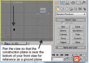
FIG 5.1
1. Activate the front viewport.
2. Pan the screen so the construction plane is near the bottom of the viewport. See Fig. 5.1.
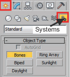
FIG 5.2
3. Select Systems in the Create Panel and select Bones (Fig. 5.2).

FIG 5.3
4. Start the leg bone by left clicking where you would expect the hip joint to be.
5. Move the cursor down and to the left, and click to create the thigh. Move down to the right and click to create the shin. Move the cursor and click twice more to create the foot and toe bones. Right click to end bone creation. You will see a small bone created at the end of the toe (Fig. 5.3).
The length of the bones does not have to exactly match the image in Fig. 5.3. We can edit these later on using the Animation MenuBones Tools Command. It is important that you click all the way through the bones you want to create in the chain, otherwise you will need to link the bones together. By default, it will link them together as created. The small nubs at the end of IK chains are for two purposes: one as the end effector and the other as an extra link at the end of the toe bone. When you create a bone, the pivot for it is at the top of the bone. Later on when we add an IK Solver to these chains to assist us in constraining and animating them, you will see that the number of bones is important.
6. Take a moment to rename the thigh bone as rig01_rt_thigh. We will rename the rest of bones in the schematic view after both set of legs are created. I will use this type of naming convention using an underline instead of spaces in case I want to export this to a game engine or work with another animator. Naming is important and you should get into the habit of assigning everything a name.
7. Switch to the left view and notice how the leg has been created centered on the construction plane that was perpendicular to the front view. We will use this as the center line in the rig. Later on when we do skinning, you will see the usefulness of the construction planes for symmetry.
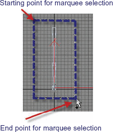
FIG 5.4
8. Enable the Select and Move Tool and drag a marquee around the leg. See Fig. 5.4.
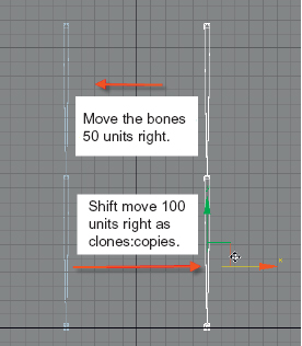
FIG 5.5
9. Move the bones to the right along the “X” axis in the left viewport. (Note the offset. You will move the clone double the amount in the other direction so both are lined up on the axis.) I moved about 50 units.
10. Using the Shift Key, move them once more to the left this time. This allows you to have the two leg bone sets offset from the “X” construction plane.
Note
I used a negative 100 on the second move.
11. When the Dialog appears, choose the Clone Option: Copy.
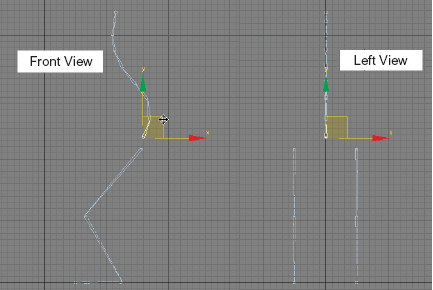
FIG 5.6
12. In the front viewport, create a backbone for your character rigging. Start the bone for the base of the spine behind the legs. You do not want to click too close to one of the leg bones because it may attach. Create about five to seven bones. Right click to end the new chain. See Fig. 5.6.
13. Select the base of the spine and rename it as rig01_spine01.
14. Move the spine01 closer to the legs as in Fig. 5.6. As you move the parent in the chain, rig01_spine01, the rest of the chain moves with it. NOTE: The more you create the better the flexibility that can be built into the back. When you right click, the node at the top of the head will be created. Use the picture below as a guide.
15. Create a camera in the top viewport and then change the perspective viewport.
16. Use the keyboard shortcut of “C” to view through that new camera.
17. Orbit the camera view so that you get a good view of the leg structure.
Note
I click to place the camera and drag to place the target. This way, when I orbit the camera, the bones will always be in the center of the view.
IK (Inverse Kinematic) HI Solvers
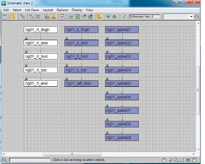
FIG 5.7
18. Open the schematic view from the Graphic Editors Menu and note which icon activates in the Main toolbar.
19. Select all the bones, right click and go into the Object Properties. Turn on Renderable. By default this is off, but I like to render it out occasionally as I work to make notes.
20. Rename the bones in the schematic view as per Fig. 5.7. Assigning the names will make it easier when you get into more complex applications with rigs.
21. After you have named the objects, select the entire right leg in the schematic view and then open the Bone Tools from the Animation Menu.
The Bone Tools will allow us to fix any problems with the chain, color it, and even add fins for depth. Having thicker bones often helps when adding skin to a custom bone setup like this. I like to also color the side of the structure similar to the green and blue coloring scheme with a biped.
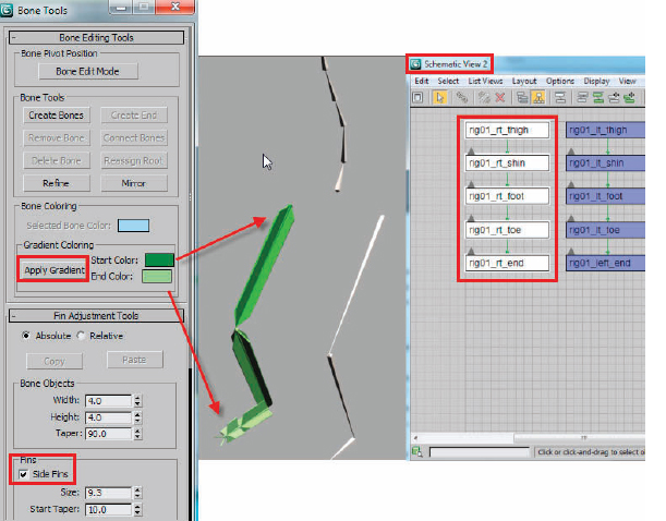
FIG 5.8
22. Change the color of the start and end of the right leg with a variation of green and hit the Apply Gradient Color. Typically, you might want green for the right and blue for the left side.
23. Enable the Side, Front, and Back of the fins and adjust these to add a little depth.
24. Repeat for the other side.

FIG 5.9
25. In the camera viewport, select one of the thigh bones.
26. From the Animation Menu, drag down and out to IK Solvers and HI Solver.
27. Move the cursor to the foot bone and click it.
As you are moving the cursor, a marquee line appears between the top of the thigh bone and the cursor. When you are done, two white lines will appear: one running through the bones showing the connection and the other from the start to end of the control. An end effector will also appear where the heel should be. This is used for animating the middle of a chain.
28. Do an edit hold before moving the end effector and testing the motion of the leg.
Hint
If you do not let go of the left mouse button and right click, the movement will be negated.
The IK chains need to be two bones as a part because the pivot of each bone is at the top of the object. To have the knee flexing when moving the thigh and shin, the end effector of the chain needs to be at the foot.
29. Select the “rig01_lt_foot” and give it an IK Solver as well, rigging it to the object at the end of the leg called “rig01_left_end”.
30. Repeat this for the right leg and also for the spine. You may want to go four to five bones away from “rig01_spine01”.
31. Save your work. I’ll save a copy of this file and call it ch5_hi_solver.max.
Creating Dummy Helpers
The next step will be to create several dummy objects to work in two different capacities. The first is to create a large dummy between the hips to work as the root or main parent of all the bone chains. It will be located between the top of the thigh bones where the hips would be. The others will be located where the end effectors are. The end effectors need to be animated but are sometimes difficult to select and move based upon their scale. The end effectors will be linked to a dummy for better control.
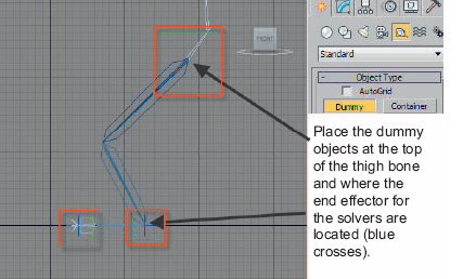
FIG 5.10
32. Activate the front viewport.
33. Go to Helpers Section of the Create Panel.
34. Click and drag three dummy helpers at the locations indicated in the picture.
Note
The hip dummy appears to be centered on the top of the hip bone and the other two on the end effectors (blue crosses).
35. Rename these objects in the Modify Panel as follows:
hip_dummy
lt_heel_dummy
lt_toe_dummy
36. Activate the left viewport.
37. Hit the “H” Key to bring up the Select by Name Dialog Box.
38. Select the two dummies called lt_heel_dummy, lt_toe_dummy.
39. Move these two dummy objects in line with the left leg that should be on the right side.
Note
Make sure you restrict the movement to just the “X” axis. This is done by click and dragging the red arrow head.
40. Hold the Shift Key and move a clone to the center of the leg on the left.
41. A Clone Dialog Box will appear. Make sure Copy is enabled and rename the copied dummy object to rt_heel_dummy, rt_toe_dummy.
42. Save the file as chpt5_hi_solver_place.
43. Go back to the Modify Panel and rename the other dummy.

FIG 5.11
44. Hit the “H” Key and select all the dummy objects. You can filter out the bone objects as shown in Fig. 5.11 by turning on the filter. Remember to turn this back on later.
45. Go into the Hierarchy Panel.
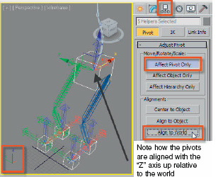
FIG 5.12
47. Click Align to world.
48. Turn off the Affect Pivot Only button when finished.
49. Save the file as chpt5_hi_solver_place_dummy01.
Note
We want to align the pivots like this so that the “Z” axis is pointed up relative to the world. When the HI Solvers are linked to the dummy objects later on, they will take on the orientation of the parent. If you forget this step, there is a swivel angle for the solvers that can be rotated at 90° angle. I just like to plan ahead so that there are no unexpected shifts of my objects. The three axes again are colored red, green, and blue. The direction of the vector is X, Y, and Z.
Linking Objects
The next step will be to link all of these objects together. Linking is useful because it makes the job of animating easier. Instead of having to transform the objects separately, we can just move the top or bottom of a chain. For example, right now the first bone you created to build the spine is the “parent” in the chain, and each bone below it is already linked as children. If we move it, the rest of the children in the chain will move with it. Let’s see what the chain looks like and then do some linking.
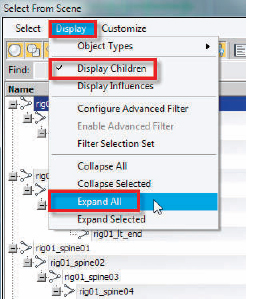
FIG 5.13
50. Hit the “H” Key and bring up Select by Name Dialog.
51. In the Display Menu, turn on Display Children and Expand All.
rig01_rt_thigh is at the far left and each bone below it is indented one space. If we renamed the bones in the leg, it would read something like the picture in Fig.5.13. Take time to rename the objects relative to Fig 5.9 if you haven’t already. You can also load the file, chpt5_hi_solver_place_ dummy01, to save some time. I just wanted you to see the fully expanded chains at this point so that if you wanted to select by name later on while linking, the object would appear as needed.
Link the end effectors of each chain to the closest dummy object.

FIG 5.14
52. Zoom in on the left foot area. Select the end effectors of the IK chain (blue cross).
53. Activate the Link button.
54. Click on the end effectors and drag to the edge of the dummy. This will Link the end effectors to their respective dummies.
Note
As you drag from the child to the parent object (IK chain to dummy), the cursor will change to the double square icon as seen in Fig. 5.14. If the choice is valid, the lower square will show in white. If you have problems dragging and selecting the right object, use the “H” Key method. Select the child, enable link, and then hit the “H” Key to select the parent by name. Objects can only have one parent, so if you do choose the wrong one, you can unlink or link to a different parent. Remember we link child to parent.
55. Repeat this linking process for all the HI Solvers to the toe and foot dummy objects.
56. Save the file as chpt5_hi_solver_linked.max.
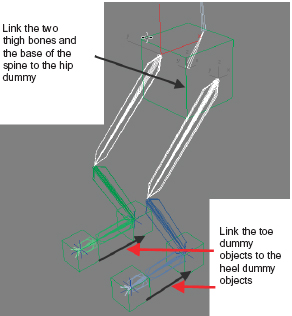
FIG 5.15
57. Do an EditHold also and then test moving the dummy objects around. If you don’t let go of the left mouse button and right click at the same time, your operation will be canceled. If the objects get moved too much while testing, just do an EditFetch.
58. Link the top of the three bone chains to the hip_dummy as well. Those should be named rig01_lt_thigh, rig01_rt_thigh, rig01_spine01.
59. Link the toe dummy objects to their respective foot dummy objects.
60. Turn off Link.
61. This is a good time to do an incremental file save.
62. Save it as chpt5_hi_solver_linked_all.max.
63. Using Select and Move Tool, move the left heal dummy back and forth on the “X” axis.
Note
Notice how the hip dummy stays in place. That is the end of the IK chain.
Note
The foot moves with the heel. In an IK chain, the end effector is used to move the chain inversely of the hierarchy linkage. In forward kinematics, we would rotate the thigh, then the shin, and finally the foot. In IK, the end of the chain pulls the parents above.
If the linking is correct, the hips when moved will pull the bottom of the spine and the tops of the hips. If you move it really far, you will see the end effectors trying to stick in place.
Undo if you moved it around too much to get back to the original pose.
Adding Position Controllers to Move the Main Hip Dummy
The final step will be to get the main parent (hip dummy) to move and adjust based upon the position of the feet. Traditional forward kinematic techniques required the animator to move the main parent and then adjust the position of the end effectors several times. The illusion of a realistic walk cycle was typically ruined by what is known as “SLIDING FEET”. This means that if the feet did not stay put as the main parent moved forward, the feet would appear to slide backward. By using some new controllers to average the position of the main parent “hip_dummy” between the two heel dummies, the hips will pull the top of the legs with it. All we have to do is animate the heels.
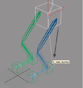
FIG 5.16
64. Select the dummy called hip_dummy. Go to the top menu bar and select: ANIMATION MENUCONSTRAINTSPOSITION CONSTRAINTS
You could also go to the Motion Panel, open the Assign Controller Panel, and assign a controller to the Position Transform. This is a shortcut.
65. A marquee line will appear attached from the center of the hip_dummy. Move the mouse over the lt_heel_dummy and click on the edge of it.
Note
In wire frame mode, you must click on the edges of objects, not the center of a face.
66. The position of the hip_dummy will be relocated to be centered on the lt_heel_dummy. This is normal. We are controlling the position of this object based upon another.
You will notice that the Motion Panel is now active in the Command Panel. All controls for the constraints you added and may want add in the future are adjusted here.
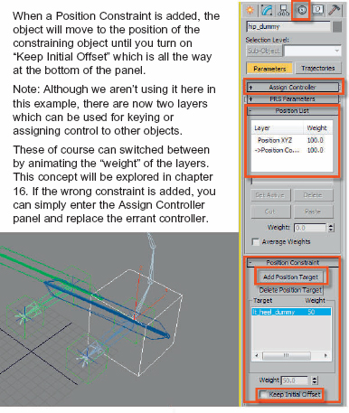
FIG 5.17
67. Pan the panel until you find the Position Constraint area.
68. Click on the Keep Initial Offset Toggle.
Result
hip_dummy returns to its initial position.
69. Click on the Add Position Target button.
70. Click on the other heel dummy object called rt_heel_dummy.
71. Turn off the Add Position Target.
Note
There is a column in the panel marked WEIGHT. Each Position Target has 50% weighting so they equally affect the position of the DUM HIP. This can be adjusted and animated over time. Think of how a character dragging a foot might lunge forward and catch itself falling in a walk. In a mechanical object, this might be a robot’s arm laboring to move into or out of a position with a heavy object.
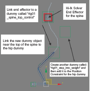
FIG 5.18
72. Create another hi-ik solver for the spine from the root to around the 7th bone.
You will have to add a dummy near the end of the spine where the shoulders would be. We will also repeat the step of linking the end effector to the dummy and then link the dummy to the hip_dummy.
73. Create two new dummy objects in the front viewport as per Fig 5.18. Call these two dummy objects: rig01_spine_top_control and rig01_step_into_weight.
74. Position both dummy objects as per Fig 5.18 and then align the pivots to the world as you did previously in the Hierarchy Panel.
The spine top control will control the near end of the spine chain while the Step to Weight dummy will allow you to have more flexibility in “throwing the weight around” for the whole rig based upon extra movement of the hip dummy. A position constraint could be used on the spine control dummy, but spine tends to move more than the hips. The hips will move the entire spine, yet you will have freedom to animate the top of the chain as you like. Before proceeding to the next step, think about moving the pivot of that spine dummy lower to mid spine or even at the hips. Instead of creating position keys for this dummy, you could create rotation keys which would appear to move on wider swinging arcs. Just a thought.
75. Link the end effector for the spine chain to the dummy near the top of the spine that you called: rig01_spine_top_control.
76. Now link that dummy to the hip dummy.
77. Turn off the linking operation by choosing the select tool. Now re-select the hip dummy and go back to the Motion Panel.
78. Left click the Add Position Target button and then left click on the new dummy for repositioning that you called: rig01_step_into_weight.
79. Turn off the Add Position Target button.
80. Save your work again at this point. Call it chpt5_rigged.
81. Turn on the Animate button, move the Time Slider 10–20 frames and move the heel dummies.
82. Create a few steps.
83. The hip dummy should be at its highest point when one leg is planted and the other is in transition between lifting and planting down. The step weight dummy will allow you to lift the hips up and force it down as you animate the steps.
Hints
You may need to create keys for a foot that needs to stay in place while the other leg is moving by right clicking on the Time Slider button.