A Miniature Chase Controller |
Chih-Lung Liu |
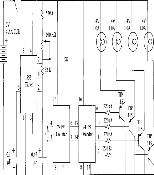
The choreographer of a production I worked on asked that her dancers’ handheld fans twinkle “like a starry backdrop.” The size and weight limitations imposed by the project gave me the chance to devise a miniature chase control circuit. This control circuit diagrammed below fits on a 2″ × 5″ electronic circuit board and costs less than $10 to build. Because of its small size and light weight, this circuit is useful for many theatrical purposes.

FIGURE 1: CONTROL UNIT CIRCUIT DIAGRAM
This control circuit uses three common IC chips to control the flow of electric power through light sources. The 555 timer is set up to oscillate at a relatively low frequency and to generate the square wave required by the 74193 up/down counter. The 74193 counts 4 binary digits worth of pulses. The 74139 dual 2-to-4 lines decoder is designed with four outputs, any three of which are normally high while the fourth is normally low. The binary input that the 74139 receives from the 74193 determines which one of the four outputs will be low at any time. A TIP115 transistor connected to each output boosts the decoder current to useable values. One pushbutton switch turns the unit on and off, and a second pushbutton switch changes the chase direction. The control unit’s adjustable resistor alters the chase rate.
Each of the lamp loads shown in Figure 1 symbolizes one of the four chase branches controlled by the circuit. Typically, each branch consists of a number of small light sources rather than a single bulb. The control circuit could power a group of 72 light sources — either LEDs or 2-volt incandescent lamps (#49). In a fan like the one I built, for instance, that would allow for each of the 9

FIGURE 2: COMPONENT BLOCK DIAGRAM FOR THE TWINKLING FAN
plastic-tubing rays to contain 8 light sources, series-wired into 4 sets of 2 lamps each. See Figure 2. This arrangement would keep one pair of light sources on each of the 9 rays (a total of 18 light sources) lit at the same time.
In building the fans, I cut a Frisbee® in half and joined the halves as shown in Figure 2. The Frisbee® sandwich provided a housing for the electronic components and a base for the feathers and plastic-tubing rays. A ¼″ plywood plate and battery-access cover sealed the open side of the sandwich.
