F. Leonard Darby |
A System for Rotating Linked Periaktoi |
The principal scenic feature in the East Carolina University production of A Chorus Line was a row of nine 14′–6″ tall periaktoi set parallel to plaster. Since A Chorus Line is about dance, it was essential that our periaktoi rotate from spike mark to precisely located spike mark in perfect synchrony, regardless of their speed. As Technical Director for the production I considered and ruled out several means of rotating the units: friction drives, worm gear drives, and chain drives with a sprocket on each periaktos — all would be too expensive or time-consuming. But finally, after batting some ideas around with Pete Feller, Jr. of New York’s Feller Precision, I devised the cable-and-drum system detailed here.
In this system, each of our nine periaktoi was mounted on its own shop-built cable drum and rotated on two pivots, one attached to the bottom of the drum and the other to a plywood plate fastened to the top of the periaktos. Figure 1 illustrates one periaktos′ assembly and shows it in position with the others.
PERIAKTOS AND DRUM DETAILS
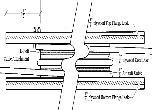
Each drum consisted of a core disc of ¾″ plywood sandwiched between two ¼″ plywood flange discs. Setting the diameter of the flange discs at 3′-11½″ allowed us to cut two flanges from a single sheet of plywood. The 3″ difference between the diameter of the flange discs and the 3′-8½″-diameter core disc left a 1½″ groove all around. See Figure 2.
Since the faces of the periaktoi were 4′–0″ wide, the points of the periaktoi overhung their drums by 4″, as shown in Figure 3. We blocked each periaktos up on a set of ¾″ plywood pads so that it would easily clear its neighbor’s drum during rotation.

FIGURE 1: PERIAKTOS ASSEMBLY
THE DRIVE DRUM
A tenth drum, identical in size and construction to those under the nine periaktoi, served as a drive drum. We bolted a sturdy 3′–″-diameter pedestal table to its top. By turning the table, the operator had no difficulty at all in making the 16 scene-shift rotations required for each performance.


FIGURE 3: PERIAKTOI IN ROTATION
THE CABLE RUN
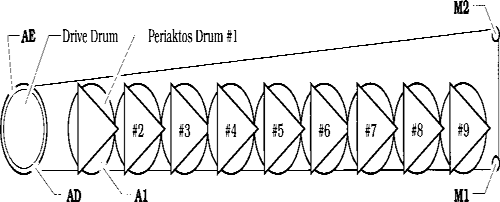
Figure 4 illustrates the linkage of all 10 drums. We attached plastic-coated ⅛″ aircraft cable to the drive drum at point AD and wrapped it twice, counterclockwise, around the drum. We then ran the cable to periaktos drum #1, where we wrapped it twice, counterclockwise, and secured it at point A1. After repeating this sequence of double wraps and attachment at each of the remaining drums, we reeved the cable through two floor-mounted muling sheaves (M1 and M2), wrapped it once more past point AD on the drive drum, and attached it to the drive drum at point AE. Though it limited our rotation options, attaching the cable to the drums assured synchrony.

At each point of attachment to a drum, we stripped the cable of its plastic coating and bolted it to the plywood flange with the u-bolt side of a cable clamp, as shown in Figure 2. Before installing the cable, we took care to align the periaktoi and to lock them in position temporarily. As we ran the cable, we simply pulled it as tight as possible by hand — an approach which worked well enough that no subsequent tension adjustment was necessary.
As the drums rotated, the cable would occasionally “walk across itself” as it served onto a drum, but the flange discs kept the cable seated properly, and the drums were large enough in diameter that the cable never jammed.
