Joanne Chang |
A Quick-Load Floor Pulley Design |
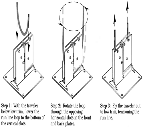
The traditional adjustable floor pulley has two drawbacks when installed in a traveler system that flies. If it is flown out with the traveler, it poses a safety hazard. If it is detached from the system and left fastened to the deck, re-rigging the traveler’s run line and reattaching the pulley takes time. Developed for the 1999 tour of Yale Repertory Theatre’s Geography II: Tree, the alternate design described here solves those problems. In addition to a base plate and two trapezoidal gussets, each pulley comprises two similar but not completely identical sheave plates. Each sheave plate consists of two pieces of bar stock: one, a rectangle: the other an L-shaped piece which “surrounds” the rectangle, leaving a ½″-wide L-shaped slot between the two pieces. This slot allows quick loading of the run line. Figure 1 shows how the run line is installed; Figure 2 illustrates the relationship between the sheaves, spacers, and plates: and Figure 3 details construction of the floor pulley components.

FIGURE 1: INSTALLING THE RUN LINE
NOTES
Though originally designed to expedite load-in during a tour, this floor pulley would also serve as a useful addition to stock rigging hardware. It can be attached to the stage floor with ¼″-diameter lag bolts or, alternatively, held in place by stage weights. Milling the holes for the sheaves’ axle bolts into horizontal slots and fitting the axle bolts with wing nuts would make the tension this style of floor pulley supplies adjustable.

FIGURE 2: EXPLODED VIEW

