A Telescoping Fire Pole |
Chris Weida |
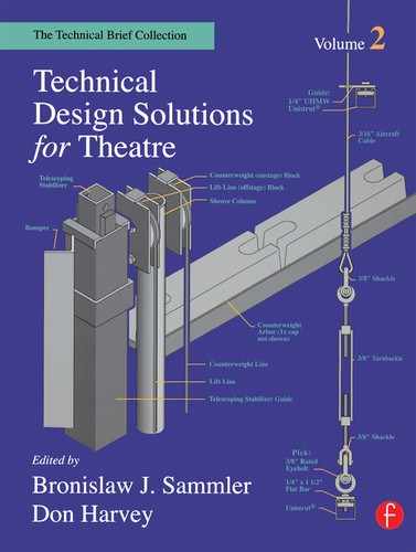
What better way for a fireman to enter the scene in a farce than by sliding down a fire pole that has just come plunging through the ceiling of the set? None, apparently, for that’s exactly how the script describes the action in Pave1 Kouhout’s Fire in the Basement. But what if the fire pole needs to be over 20′ long and there’s only 9′ of usable headroom above the set? Dennis Dorn and Chuck Mitchell faced that exact problem in the University of Wisconsin-Madison’s 1991 production of the play. Figure 1 at the right offers an overview of their solution: a telescoping fire pole that is extended rather than simply flown in.
The rig they designed included a pneumatic cable cylinder mounted above the set, and three sections of schedule 40 black pipe of different diameters that, like sections of a telescope, nested one inside another. The largest of the pipes, 2½″ in diameter, did not move. But the two smaller pipes, 2″ and 1 ½″ in diameter respectively, descended simultaneously until the middle pipe stopped at its low trim some 6′ off the stage floor, leaving the bottom pipe to travel on alone. During reset, the cylinder lifted the bottom pipe off the floor: and as the bottom pipe rose, it was drawn up inside the middle pipe, which it carried along until both pipes had fully retracted into the fured top pipe, at which time a new paper-covered plug was installed to repair the ceiling.
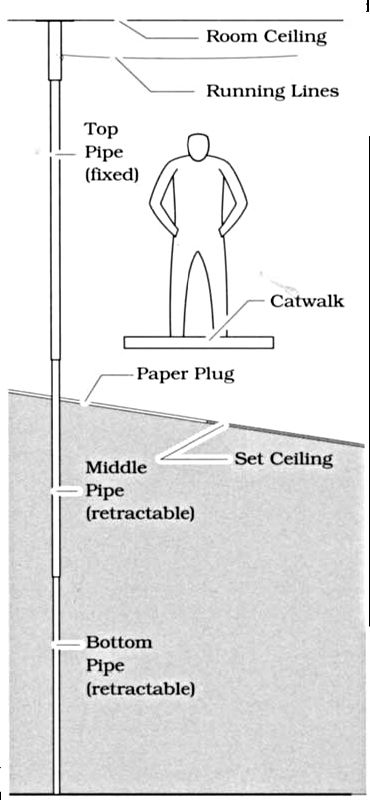
FIGURE 1: PARTIAL SECTION LOOKING LEFT
HARDWARE DETAILS
Figures 2A, B, and C illustrate the various fittings. A shopbuilt channel (Figure 2A) made from angle iron and three lengths of steel bar and bolted to the upper 6″ of the 2½″ pipe held the pole’s top pipe in place. For this particular installation, the channel was capped by a fourth length of steel bar which secured it directly to the theater’s ceiling. The legs of the channel supported two ¼″ rods. One of these rods served as an axle for a pair of 2″ wire-rope sheaves mounted just above the top pipe; the other kept the cables seated in the grooves of the- sheaves. A ![]() hex head bolt through the assembly joined the fured pipe to the channel and stopped the travel of the other two pipes before they could hit the sheaves.
hex head bolt through the assembly joined the fured pipe to the channel and stopped the travel of the other two pipes before they could hit the sheaves.
The sheaves mounted in the channel guided two ⅛″ wire-rope lift lines along the pole’s axis. As Figures 2B and 2C illustrate, one of these lift lines picked up the middle pipe at a ½″ steel rod near the pipe’s upper end: and the other picked up the bottom pipe at a similar rod through the pipe’s lower end.
The pneumatic cylinder lifted both traveling pipes. The middle pipe’s loft line was lightly counterweighted so that it would be drawn out of the pole during retraction, but the rig was nevertheless left deliberately stage heavy so that the middle pipe would ride in with the bottom pipe. As the pipes flew in, the middle pipe’s lift line stopped the middle pipe at its low trim while the bottom pipe moved on. At the stage floor, the chamfer at the lower end of the bottom pipe guided the base of the pole into a 2″ socket drilled into the floor of the stage.

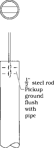
FIGURE 2B: MIDDLE PIPE DETAIL
FIGURE 2C: BOITOM PIPE DETAIL
STABILITY
The solid built connection at the pole’s top and the relatively deep socket connection at its base gave the pole a great deal of stability, and the designers enhanced that stability by leaving generous amounts of overlap between the sections of pipe. As a result, the first actor down the pole each night was not at all nervous about the prospect of grabbing the pole and sliding blithely — and somewhat blindly — downward, through the paper plug in the ceiling of the set.