A Pneumatic Floor Lock System |
Delbert L. Hall, Ph.D. |
There are many solutions to the problem of locking rolling units in place following a scene change (see Mark Stevens’s Technical Brief “A Simple Lift Jack” for one method). However, the solution to this problem becomes more difficult when all sides of the unit must be faced, the unit must be moved quickly and easily by a single person, and the unit must remain stationary under the movement of actors performing stage combat. We faced this set of conditions in a production of Romeo and Juliet at East Tennessee State University. The solution we selected was a pneumatic floor lock system.

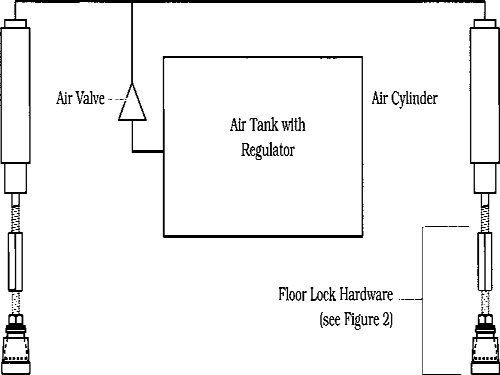
FIGURE 1: SYSTEM SCHEMATIC
Floor locks, unlike lift jacks, do not lift the unit. Instead, a non-skid pad on the bottom of the floor lock applies downward pressure on the floor, serving as a brake. Commercial toe-operated floor locks, which are used in pairs, have been available for many years. However, since our unit had to be faced on all sides, a toe-operated device was impractical. Instead, we used air cylinders to construct floor locks which could be operated by a single valve, recess mounted on the face of the unit. An air tank mounted inside the rolling unit supplied the air for the cylinders. Our system used two locks on each rolling unit.
The dimensions of our 18″-tall rolling unit were 2’-6″ × 6’-0″. These dimensions influenced some of our component choices — particularly the size of the air tank. We used a 6-gallon air tank because it was in stock. We have experimented with smaller tanks constructed from 2½″ schedule 40 black pipe, and plan to use them on lower rolling units.
MAJOR COMPONENTS FOR ONE ROLLING UNIT
2 ea. 1 ½″ bore, adjustable-stroke, single-acting Air Cylinders
1 ea. 3-way, 3-port, 2-position Toggle Valve
1 ea. 6-gallon Air Tank with regulator
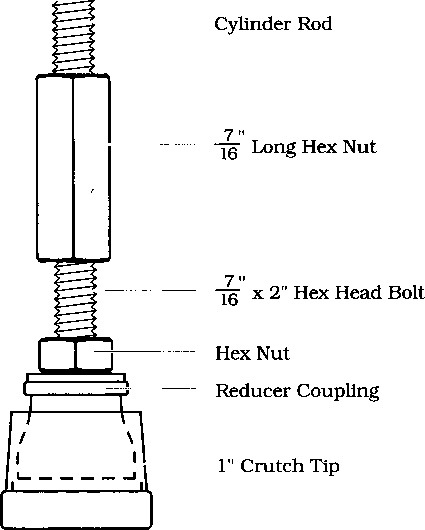
2 ea. 1″ Crutch Tips (the brake pads)
2 ea. ½″ × ⅜″ galvanized Reducer Couplings
2 ea. ![]() × 2″ Hex Head Bolts
× 2″ Hex Head Bolts
2 ea. Long Nuts for ![]() Threaded Rod
Threaded Rod
Appropriate lengths of ½″ Copper Tubing and a number of ⅛″NPTF fittings.
CONSTRUCTION DETAILS
One air cylinder was mounted on the inside of each end of the unit so that the extended foot would apply pressure to the floor. The air tank was mounted inside the unit, the air valve was recess-mounted on one face of the unit, and all components were connected by ⅛″ copper tubing. We found that 40psi provided enough pressure to keep the unit from rolling, even under the most strenuous actor traffic. It should be noted that the unit was built to be very heavy. A lighter prototype had been lifted off the floor by 40psi air pressure. We used rubber crutch tips as the non-skid surface on the foot of each lock: they were easy to apply and worked well enough that we tried no other materials or designs for brake pads.
The system worked very efficiently and made it possible for an actor to reposition the unit during scene changes. We were very satisfied with the system’s operation and plan to use it on both larger and smaller rolling units in future productions.

FIGURE 2: FLOOR LOCK HARDWARE
