A Quiet Glide and Unistrut® Traveler System |
Chuck Adomanis |
To avoid the noise typically associated with traveler tracks, the technical designers for the 1997 Yale Repertory Theatre’s A Midsummer Night’s Dream developed a system that used P1000 Unistrut® in place of standard traveler track and UHMW glides in place of wheeled carriers to support a pair of tube steel framed flats. This article details construction of the glides.

FIGURE 1: UHMW GLIDE AND P1000 UNISTRUT® TRACK
UHMW was chosen for its low coefficient of friction and machinability. In constructing the glides, blocks of UHMW were cut to 1½″ × 1½″ × 12″ and then machined down to the section pictured in Figure 1. The section was designed not only to act as a glide, but also to incorporate all of the hardware connections for hanging the legs and securing the drive cables. Blanks were cut to 3″ lengths and then the holes for the cable, set screws, and leg hardware were bored and tapped as necessary. The tapped holes were intended for setscrews which would secure the glide to the drive cable. Though ultimately not used for that purpose in this application, their effectiveness to hold onto the cable was tested. In repeated tests, significant damage was done to the cable before the glide was harmed.
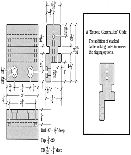
Figure 2 shows the ideal dimensions for the glides. Most of the glides were made with standard woodworking tools (table saw with dado blade, radial arm saw, and drill press), and tolerances were fairly relaxed. One pair of glides, however, was produced using the school’s machining tools: vertical mill, drill press, and lathe. The more precisely machined set of glides performed better, but the sets made with woodworking tools worked well enough to be used in this application.
The 6′-0″ × 16′-0″ legs supported by the glides were framed in 1″ × 1″ × 0.035″ tube steel to reduce weight. Weld-nuts inserted through the front of the top rails accepted ![]() flat head stove bolts inserted through the back of the glides. Covered with Duvetyn®, the legs weighed approximately 60 pounds each. Each leg was fitted with two glides and no friction problems were ever experienced. Initially, the designers anticipated that a pair of glides could not carry more than 100 pounds. Though no ratings can really be applied, subsequent experience has shown that they perform
flat head stove bolts inserted through the back of the glides. Covered with Duvetyn®, the legs weighed approximately 60 pounds each. Each leg was fitted with two glides and no friction problems were ever experienced. Initially, the designers anticipated that a pair of glides could not carry more than 100 pounds. Though no ratings can really be applied, subsequent experience has shown that they perform

FIGURE 2: IDEAL TOLERANCE FOR UHMW GLIDE
beyond this limit with no problems. For one production, two carriers were used to support a 3′−0″ × 18′−0″ flat framed in ![]() pine, covered with 1¼″ medium density fiberboard, and stiffened with 1½″ × ⅛″ angle iron. That unit weighed upwards of 150 to 200 pounds.
pine, covered with 1¼″ medium density fiberboard, and stiffened with 1½″ × ⅛″ angle iron. That unit weighed upwards of 150 to 200 pounds.
Since the first round of glides was machined, several more have been made, each customized to improve on the design. Typical changes have included changes in the cable/rope location in the carrier, number of cables running through the carrier, and mounting details between carrier and scenic element. The most effective of these variations, one in which two ⅛″ cables are used, requires the stacking of the cables and the addition of a second set of locking screws as shown at the right in Figure 2. This has necessitated the use of P1000HS slotted Unistrut® to allow access to the top of the glide, which has the added advantage of reducing the weight of the channel by a noticeable margin. It is also important to note that glides have been developed for use with rope, which are useful in manual operations. I recommend that glide “blanks” be made in quantity, and that mounting and cable/rope holes be added as necessary. Requiring only basic machining tools and skills, and using relatively inexpensive materials, the glides have been a great success and will undoubtedly be useful in future productions.
