A Sure-Shot Fireball Effect |
Dave King |
The director of PCPA’s Damn Yankees wanted the devil character, Applegate, to pitch a flash-paper fireball like a baseball — a neat trick for performer and technician alike. For the trick to be effective and safe, Applegate would need control over its ignition and trajectory. Figures 1 and 2 show the launcher we built which met both needs. Its circuitry allowed instantaneous firing at any time during the actor’s wind-up and delivery, and its barrel provided at least reasonable control over the flash paper’s flight path.

FIGURE 1: ARMING UNIT & FIRING UNIT

FIGURE 2: PALMING THE FIRING UNIT
THE COMPONENTS
The launcher consists of two distinct assemblies — an Arming Unit and a Firing Unit — joined by arm’s-length leads of 28-gauge wire sewn into the actor’s costume. The Arming Unit consists of 4 AA batteries lying side by side in a shallow plastic case for maximum concealability. A recessed slide switch mounted on a separate case is the launcher’s arming switch. (The tab of electrician’s tape over the switch in the photo helped keep our Applegate’s movements from accidentally disarming our launcher.) The LED “armed” indicator above the slide switch lights up whenever the circuit is on.
Figure 1 also shows the parts of the Firing Unit: a 3¼′ barrel made of ⅜″ brass tube and fitted with a 6″ length of ½″ brass strap. The strap wraps around the actor’s first and index fingers, holding the firing pushbutton, as well as the barrel, securely in place.
Figure 2 shows how easily and comfortably the Firing Unit can be concealed by an actor’s hand.
CONSTRUCTION NOTES
All dimensions noted in Figure 3 should be treated as guidelines only, for launchers of this sort are “actor-specific.” The length of the brass strap for the finger mounts and the length of the barrel will depend on the size of a given actor’s hand. It is also helpful to know in advance whether the actor involved is right-handed or left-handed, for the pushbutton is thumb-operated. We secured the two sides of the strap together with a small brass screw whose point we then ground smooth.
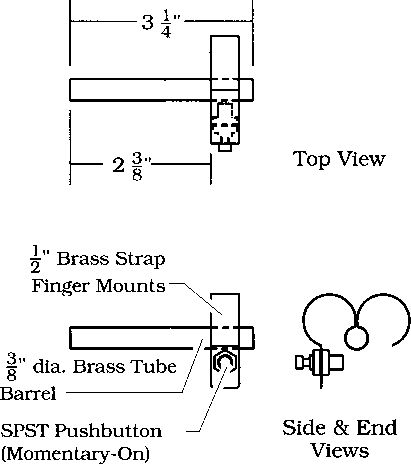
FIGURE 3: BARREL CONSTRUCTION

FIGURE 4: CIRCUITRY
Figure 4 details the assembly of the launcher’s circuitry. To assure instantaneous ignition, we used Estes Model Rocket Igniters instead of the more common electric matches to fire the effect. Estes, located in Penrose, Colorado, can be reached at (719) 372-6565.
PREPARATION AND LOADING NOTES
Before loading the launcher, make sure the arming switch is off and the batteries are removed. See Figure 5 for a step-by-step guide to preparation and loading.
A single igniter would fire the effect, but ganging a pair of them and heat-shrinking the ganged leads has advantages. Ganging igniters provides a form of assurance — at least one of the two is likely to fire. The heat shrink reinforces the igniters’ leads and defeats the possibility that they will short out against each other or the brass barrel. A collar of electricians’ tape wrapped just below the igniters’ heads provides strain-relief against wishboning.
The amount of flash paper used and the diameter of the launcher’s barrel together govern how big a fireball will be, how far it will fly, and how loud the effect’s popping sound will be. Needless to say, experimenting in the shop prior to tech is recommended.
The last steps before making the electrical connections are to bend the protruding igniter leads down so they will fit comfortably in the performer’s hand, and to carefully seal the rear of the tube with electrical tape. This seal must be sound enough to protect the performer’s hand from the brief but quite intense “blow-back” firing the launcher produces.
ELECTRICAL CONNECTIONS
After sealing the flashpaper wad and the igniter into the barrel, bend the ends of the igniter leads through the holes in the male disconnect terminals coming from the Arming Unit and the “fire” pushbutton. Wrap these contact points in electrical tape to provide strain relief and prevent electrical shorting. Then lay them on top of one another and bind them together to provide further strain relief. Before reloading the batteries, double check that the Arming Unit’s switch is off.
FINAL NOTES
A director’s desire to produce pyrotechnics from a performer’s person is something no Master Electrician or Properties Master likes to hear. This device offers a production a reliable and safe solution that can be made for as little as $20 with parts obtained at Radio Shack or any other hobby store. Over the course of a 24-performance run, the device achieved a 96% success rate. Safety is enhanced by the control gained over exactly when the device fires and therefore over the direction in which the burning flash paper is sent. Nevertheless, state or municipal fire regulations would prohibit the use of this device in many localities. Before planning to build one, check with the local Fire Marshal.
The author would like to thank PCPA’s Lighting Director Mike Peterson and Properties Director Tim Hogan for their help in developing this device.

FIGURE 5: PREPARATION AND LOADING