Kevin Hines |
Flexi-Pitch Escape Stairs |
Up to a point, saving time and money by using stock escape stairs is a good practice, but too many fixed-pitch escapes are pressed into service even when they aren’t exactly the right height. Such practice is inelegant at best and unsafe at worst. Furthermore, as many technicians and manufacturers have discovered, it is ultimately unnecessary. This article describes a design for a variable-pitch staircase.

FIGURE 1: A 4-TREAD FLEXI-PITCH STAIR SET AT THE EXTREMES OF ITS USABLE RANGE
GENERAL DESCRIPTION
The carriages of these open-riser stairs consist of two parallel lengths of tube steel which serve as stringers, and a number of pieces of angle iron which support the treads. The single bolt connections joining the carriage components are essentially pin joints. As a result, a fully formed stair folds nearly flat for storage and its treads remain uniformly level and evenly spaced regardless of the angle at which they are set for a specific use. As Figure 1 and the tables at the end of this article illustrate, this design allows a single stair to be angled to suit a wide range of platform heights.
HARDWARE SPECIFICS
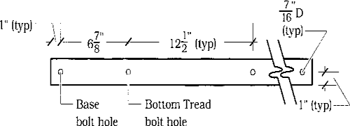
Figure 2A details the fabrication of a camage’s stringer: a length of 1×2 steel tube with a series of ![]() diameter holes drilled along the centerline of its 2″ walls. Figure 2B depicts the typical base or plain ledger: an 11¼″piece of ⅛″× 2″ × 2″ angle iron drilled with
diameter holes drilled along the centerline of its 2″ walls. Figure 2B depicts the typical base or plain ledger: an 11¼″piece of ⅛″× 2″ × 2″ angle iron drilled with ![]() diameter holes, each centered 1″ in from the end and 1 ½″ away from the angle’s spine. Uniform hole spacing makes all base and plain ledgers reversible and interchangeable. Figure 2C depicts the distinctive stem of the stemmed ledger: a 9¼″long upright of ⅛″ × 2″ × 2″ angle iron drilled to allow bolting to a leg or a platform. Note that one hole in the stemmed ledger’s horizontal member is inset 3″ rather than the typical 1 ½″ from the end to provide clearance for any leg that might be used with the stair.
diameter holes, each centered 1″ in from the end and 1 ½″ away from the angle’s spine. Uniform hole spacing makes all base and plain ledgers reversible and interchangeable. Figure 2C depicts the distinctive stem of the stemmed ledger: a 9¼″long upright of ⅛″ × 2″ × 2″ angle iron drilled to allow bolting to a leg or a platform. Note that one hole in the stemmed ledger’s horizontal member is inset 3″ rather than the typical 1 ½″ from the end to provide clearance for any leg that might be used with the stair.


FIGURE 2B: BASE/PLAIN LEDGER

FIGURE 2C: STEMMED LEDGER
Figure 3 details the construction of the triscuit (stressed-skin) tread intended for use with this carriage design. Tread width is set at 11 ¼″; tread length must be calculated to suit particular stock platform legging requirements. Since at steeper pitches the stair needs to underhang the plat-forming in order to maintain consistent tread width, the tread length must allow the entire carnage to stand between the legs of a stock platform.

FIGURE 3: TRISCUIT TREAD
GEOMETRY
This stair design is based on three constants: an 11 ¼″ tread width, 2⅜″ tread thickness, and a 12½″ normal hole-to-hole spacing between tread bolt connections along the carriage. All other values are derived for each pitch as shown in Figure 4.
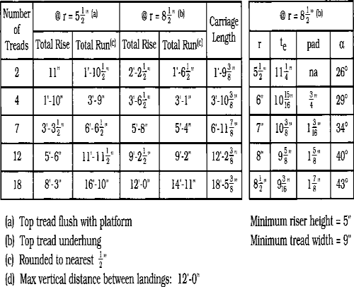
The tables below summarize the design data for five different stair units. Note particularly that at the gentlest pitch, the stairs’ bases sit directly on the floor. At any other pitch, however, the base must be shimmed up in order to provide the right riser height for the first tread.

FLEX-PITCH STAIR DESIGN DATA

