A Jig for Cutting Ellipses |
Michael Parrella |
For the Boston University School for Theater Arts’ production of The House of Bernarda Alba, the set design was very simple — principally a large, elliptical raked deck. The ellipse’s major and minor axes measured 32′-0″ and 26′-0″, respectively. The major axis sat at a 30° angle to the stage centerline, but the slope of the rake was parallel to the centerline. To speed up load-in, I decided to build the deck of as many 4x8 platforms as possible that could be installed parallel to the centerline. The most straightforward construction approach was to lay out and cut the ¾″ plywood skins and then frame the platforms. Still, cutting an ellipse of that size was a challenge.

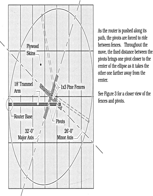
FIGURE 1: OPERATION OF THE JIG
Given the tight schedule and the relative inexperience of the staff, the likelihood of cutting a clean ellipse with a saber saw seemed unlikely. Using a line anchored at the ellipse’s foci to guide a router seemed no less promising — even aircraft cable stretches. The likeliest approach involved mounting a router on a two-pivot trammel arm. I had seen a jig like this used successfully to cut elliptical sweeps for moulding, and though that ellipse had been much smaller (its major axis measured only about 6′-0″) the approach had worked well. Figure 1 illustrates the jig’s operating principles.
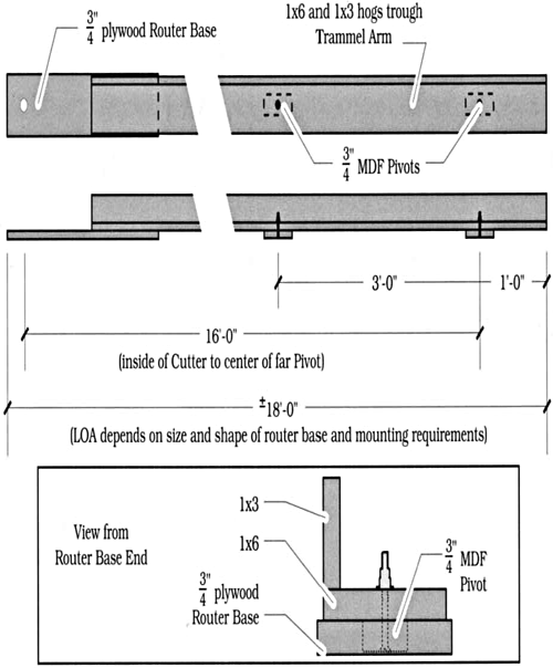
Figure 2 details the construction of the trammel arm we built, essentially a nominal 1x6 and 1x3 hogs’ trough with a ¾″ plywood router base attached to one end and two pivot blocks bolted near the other end, still able to pivot. For our purposes, a 16′-long 1x6 was just barely long enough since the distance between the inside cutting edge of the router bit and the center of the further pivot must be equal to one-half the length of the major axis: 32′-0″ + 2 = 16′-0″. So that we could leave 1′-0″ between the further bolt hole and the end of the 1x6, we oversized the long dimension of the plywood router base by 1′-0″.

FIGURE 2: CONSTRUCTION DETAILS
The pivots were 2″ × 5″ rectangular blocks of ¾″ Medite® (MDF), and the distance between them was set according to the formula “distance equals one half the length of the major axis minus one-half the length of the minor axis”: (32′-0″ ÷ 2) minus (26′-0″ ÷ 2) = 3′-0″. Math located the pivots’ bolt holes at 13′-0″ and 16′-0″ from the inside of the cutting edge of the straight-flute plunge router bit.
With the trammel-arm built, we laid out 28 sheets of ¾″ plywood in a 32′-0″ × 28′-0″ rectangle. We then laid the axes in with a chalk line and screwed 4′-long nominal 1x3 pine fences to the plywood as in Figure 3, leaving a 2″-wide track and a little extra space between them so that the MDF pivots would slide easily.
Operation of the jig required three people: one person spotting each pivot point as it rode in between the fences, and one person operating the router. On our first pass, we learned that the pivots needed to ride more snugly between the fences than we had thought: the first pass with the router left a 1″ variance between the start and end of the cut. By bringing the fences closer together and then coating them with butchers wax to counter the friction, we reduced our initial variance by half.
Although this jig seemed somewhat cumbersome at times, it was inexpensive, took little time to build, and, for a one-time use, served its intended purpose quite well.

FIGURE 3: A CLOSER VIEW OF THE FENCES AND PIVOTS
