Chapter IIA-2
Calibration, Testing, and Monitoring of Space Solar Cells
Chapter Outline
2.2.4. Differential Spectral Response
2.3. Secondary Working Standards
3. Testing of Space Solar Cells and Arrays
3.1.2. Relative Spectral Response
3.1.3. Reverse Characterisation
3.1.4. Capacitance Characterisation
3.2.7. Electrostatic Discharge
3.3. Physical Characteristics and Mechanical Tests
4. Monitoring of Space Solar Cells and Arrays
4.2. Monitoring of Solar Array Performance in Space
4.3. Spacecraft Solar Array Anomalies in Orbit
4.3.1. European Communication Satellite (ECS) and Maritime European Communication Satellite (MARECS)
4.3.2. X-Ray Timing Explorer (XTE)
4.3.4. Pioneer Venus Orbiter SA
4.4. Postflight Investigations on Returned Solar Arrays
1 Introduction
Solar energy is the main power source technology for most spacecraft since the 1960s. A total failure of the solar array (SA) performance will lead to complete mission loss. SA behaviour in the space environment has to be predicted in order to assure endurance during mission life.
The SA electrical performance is a basic parameter that needs to be predicted for mission life, tested on the ground, and monitored continuously in space. Electrical performance (EP) at beginning of life conditions is measured on the ground to check power output prediction, based on performance measurements of single solar cells and before their integration on the SA. These measurements are performed with solar simulators, having adjusted their light intensity to standard AMO illumination conditions with suitable reference solar cells. Reference cells are space calibrated using different methods that will be described in Section 2.
Endurance of the SA to the space environment has to be simulated by ground environmental testing. Different mechanical and environmental tests, together with electrical tests for degradation assessment, are performed at the different steps of development, manufacture, and integration of SA components and intermediate assemblies. An overview of these tests is given in Section 3, mainly focused on tests at solar cell levels.
Monitoring the performance of the SA in orbit is essential to validate the predicted behaviour during the mission, and this provides valuable data for verification of ground testing and further SA design improvements. Section 4 deals with the monitoring of spacecraft SA in orbit. Flight experiments are conducted to assess the performance and behaviour in space of novel solar cell or SA integration technologies. Two other important sources of data are unpredicted anomalies in orbit and investigations carried out on SAs returned from space.
2 Calibration of Solar Cells
Standard solar cells are used to set the intensity of solar simulators to standard illumination conditions, in order to electrically characterise solar cells with similar spectral response. Space calibration methods of solar cells can be extraterrestrial when performed outside the atmosphere or synthetic if they are carried out on the ground, using natural sunlight or indoor simulated illumination [1]. To prevent continuous handling operations of the expensive extraterrestrial/synthetic cells, so-called secondary working standard solar cells are calibrated for routine electrical performance testing in industry and testing laboratories.
2.1 Extraterrestrial Methods
Two calibration methods are the main suppliers of extraterrestrial standards: the high-altitude balloon and the high-altitude aircraft. Both methods require minimum data correction due to the small residual air mass at the altitude where the calibration is performed.
2.1.1 High-Altitude Balloon
Calibrations are performed on board stratospheric balloons flying at altitudes of around 36 km, where the illumination sun conditions are very close to AMO. Cells to be calibrated are directly exposed to the sun, mounted on supports with sun trackers. Currently, two institutions, JPL-NASA in the USA [2] and CNES in France [3,4], are conducting, on a yearly basis, these calibration campaigns. The main differences between the two calibration institutes are the position of the cells, which in the case of JPL-NASA is mounted on the balloon apex and in the case of CNES, is a gondola hanging from the balloon. Both institutes correct calibrated data, taking into account the effect of temperature and the variation of illumination due to the Earth–Sun distance variation over the year. CNES also corrects its calibrated data, taking into account the effect of the residual atmosphere.
2.1.2 High-Altitude Aircraft
Calibrations are performed on board of an aircraft capable of flying at altitudes of 15–16 km. Cells are mounted at the end cap of a collimating tube on a temperature controlled plate. NASA Glenn Research Centre is currently conducting more than 25 flights per calibration campaign using a Gates Learjet 25 equipped even with a spectroradiometer to measure the solar spectrum at that altitude. Data are corrected for the ozone absorption, the geocentric distance and extrapolated to the air mass value of zero [5].
2.1.3 Space Methods
The most realistic environment on which calibration of solar cells can be performed is indeed outside the atmosphere. The first constraint of these methods is their relatively high cost compared with the other two extraterrestrial methods and their lower level of maturity.
• Space shuttle: On board the space shuttle, the Solar Cell Calibration Experiment (SCCE) was conducted in two flights in 1983/84, where solar cells from different agencies, institutions and space solar cell industries around the world were calibrated and returned back to Earth [6].
• Photovoltaic Engineering Testbed: This is a NASA-developed facility flown in the International Space Station, where after exposure and calibration of cells in the space environment, they are returned back to Earth for laboratory use [7].
• Lost Twin: This is an ESA-proposed method, based on the flight of several solar cells on a nonrecoverable spacecraft. Cells nearly identical to the flight ones are kept on Earth. The orbiting cells are calibrated and these calibrated values are given to their respective twin cells.
2.2 Synthetic Methods
There are two methods carried out under natural sunlight conditions.
2.2.1 Global Sunlight
The cells to be calibrated and a pyranometer are placed on a horizontal surface, where simultaneous readings of spectral irradiance over the sensitivity range of the pyranometer and short-circuit current of the cells are recorded in global sunlight. The calibration site environmental conditions need to fulfil several requirements relating to global and diffuse irradiance levels, solar elevation, unobstructed view over a full hemisphere, etc. The calibrated short circuit current of the cell is calculated by means of the following formula:
![]()
where k1Sλ is the absolute spectral response of the cell, k2Egλ the absolute spectral irradiance of the sun at the calibration site, ESλ the AM0 spectral irradiance, Eglob the pyranometer irradiance reading, and Isg the measured short circuit current of the cell.
The final calibration value is the average of three calibrations of three different days. The former RAE (UK) performed for several years global sunlight calibrations at Cyprus [8] and presently INTA-SPASOLAB (Spain) is performed on a yearly basis in Tenerife [9,10].
2.2.2 Direct Sunlight
The cells to be calibrated are placed on the bottom plate of a collimation tube, a normal incidence pyrheliometer and a spectroradiometer are kept pointing to direct sunlight while measurements of short-circuit current, total irradiance and spectral irradiance are recorded. Several conditions need to be fulfilled by the calibration site and its environment, i.e., certain irradiance level, stable cell short-circuit readings, ratio of diffuse to direct irradiance, etc. The calibrated short circuit current of the cell is calculated by means of the following formula:
![]()
where Isd is the measured short circuit current, Edir is the total solar irradiance, Edλ is the spectral solar irradiance, Esλ is the AM0 spectral irradiance, and sλ is the relative spectral response of the cell to be calibrated.
The calibrated short circuit current value is the average of three calibrations performed in three different days. CAST (China) presently performs calibrations following this method [11].
The following two methods are carried out under simulated sunlight.
2.2.3 Solar Simulator
The cell to be calibrated is illuminated by means of a steady-state solar simulator adjusted to 1 AM0 solar constant with a previously calibrated cell or a suitable detector. The spectral irradiance of the solar simulator is measured with a spectroradiometer, and the relative spectral response of the cell is measured separately. The calibrated short circuit current of the cell is calculated as follows:
![]()
where Ism the short circuit current and Emλ the spectral irradiance, both measured under the solar simulator. NASDA (Japan) regularly performs calibrations following this method [12].
2.2.4 Differential Spectral Response
The calibrated short circuit current of the cell is calculated with its absolute spectral response together with the reference AM0 solar spectral irradiance. The absolute spectral response is obtained as follows: first, the relative spectral response of the cell to be calibrated and then for certain wavelengths the absolute differential spectral response, is determined by the ratio of the cell short-circuit current to irradiance measured by a standard detector. This method was developed and is frequently presently used by PTB (Germany) for solar cell calibration [13].
2.3 Secondary Working Standards
Secondary working standard (SWS) solar cells are used to set intensity of solar simulators to standard conditions for routine measurements of identical (same spectral response) solar cells during acceptance or qualification testing. For the EP characterisation of SA, panels or coupons, SWSs are preferred for reference. SWSs are calibrated using standards obtained by the methods defined above and a continuous or pulsed light source. The measured data are corrected by means of the spectral response of both cells and the spectral irradiance of the light source and the standard AM0 spectrum, following the spectral mismatch correction method [14]. This secondary calibration method also gives relations between calibrated solar cells by different methods [15].
3 Testing of Space Solar Cells and Arrays
In order to assess the behaviour of solar cells and solar arrays for a specific space mission or environment, several tests need to be conducted at different hardware levels and phases of a project.
• Development: To know their performance, their endurance to the space environment and therefore decide on the most appropriate solar cell candidate for the the specific application.
• Design: Measured solar cell data at different environmental conditions is necessary for an accurate power prediction during the mission and therefore a suitable sizing of the solar array.
• Qualification: Verify that the solar cells manufactured in the production line meet a set of requirements defined by the specific space mission [17].
• Acceptance: To provide cell performance and physical data: essential for their further integration in the solar array electrical network.
• Higher levels of solar array components integration: The so-called photovoltaic assemblies (test specimens with all the components existing and integrated as in the solar array electrical network) are also tested in the development and qualification phases.
• Solar array level: Tests are performed in development phases and in the qualification phase of the flight hardware. These tests are required to see whether or not the solar array is integrated with the spacecraft body.
Tests on solar cells and solar arrays can be split in three types: Electrical, Environmental, and Mechanical/Physical characteristics. The following sections deal with these types of tests, focusing chiefly for their application to solar cells assemblies (SCAs); however, when relevant, their application to higher levels of solar array integration or other solar array components is described.
3.1 Electrical Tests
3.1.1 Electrical Performance
The objective of this test is to assess the corresponding electrical parameters of the solar cells and to provide data for solar generator design. The electrical current of solar cells under 1 Solar Constant AM0 equivalent illumination shall be measured and recorded at a certain voltage. A solar cell test set up consists basically of a continuous or pulsed light source, a load connected across the cell’s terminals and electrical current and voltage measurement equipment. During the measurement, the temperature of the cell junction is kept at a constant temperature (25 °C) and a four-point probe measurement of the cell is used in order to minimise the effects of lead and contact resistances [16].
Solar simulators need to meet certain requirements on their light beam spectrum, uniformity, and stability for optimum EP measurements of photovoltaic devices [1,17]:
• Spectrum: Maximum allowable deviations of spectral energy in certain wavelength regions of the standard AM0 spectrum define the solar simulator spectral quality classification. The spectral irradiance is measured with spectroradiometers [18] or special filtered solar cells [19].
• Uniformity: Uniformity of the irradiance on the test area is a critical parameter for accurate measuring of panels or SA.
• Stability: The light beam stability has to be maintained under certain values, especially when no simultaneous correction is done when measuring the EP.
Continuous or pulsed light sources are used to simulate solar illumination in laboratories or test facilities:
• Continuous solar simulators are mostly based on xenon short arc lamps where the beam is filtered and collimated to achieve the previously mentioned requirements. They are mainly used for the electrical characterisation of solar cells and small coupons. Large-area continuous solar simulators based on argon discharge lamps are used to electrically characterised solar cells or panels [20]. Multisource solar simulators are required for measuring multijunction (Mj) solar cells, in order to set equivalent AM0 illumination conditions on each subcell [21].
• Pulsed solar simulators are based on xenon large arc lamps where the beam usually is not filtered to meet the above requirements on the test plane. Either solar cells or large panels can be electrically characterised, being not heated during the test, but special techniques are needed for measuring slow response cells [22,23]. When measuring Mj solar cells, a better matching of the AM0 is needed, precisely in the near infrared spectral range, where xenon large arc lamps have less radiant energy [24].
Reference cells, either primary or secondary standards, are used to set the intensity of solar simulators to standard illumination conditions. For Mj solar cells, either so-called component cells (Mj cell structures with only one active junction) [25] or methods based on mismatch factor are followed to set standard illumination conditions on each cell junction [26].
Under standard illumination conditions and constant temperature the current voltage curve of the photovoltaic device is traced by polarising at different voltages. The shape and magnitude of the I–V curve depends on the junction characteristics, shunt and series resistance, and on total radiant energy converted, regardless of wavelength composition [27]. However, for Mj solar cells, wavelength composition of the radiant energy affects the shape of the I–V curve [28].
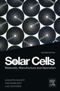
Temperature coefficients of solar cell electrical parameters can be calculated from experimental data, by measuring the device EP at different temperatures [29,30] (Table 1).
TABLE 1 Typical EP Parameters and Temperature Coefficients of Some Space Solar Cells. Abbreviations: Sj = Single junction; Dj = Double junction; Tj = Triple junction
The solar cell EP behaviour under different angles of incidence is of most importance for SA designs with curved substrates and operation of planar SA at high tilt levels. The potential angle of incidence-dependent effects are the cosine function. Fresnel reflectivity, cover-glass coatings and filters, solar cell multilayer antireflecting coating, extreme angle effects, and end-of-life (EOL) behaviour. Assessments of these effects for each SCA component combinations are needed for SA performance prediction [31].
3.1.2 Relative Spectral Response
Relative Spectral Response is the short-circuit current density generated by unit of irradiance at a particular wavelength as a function of wavelength. Relative spectral response provides valuable data for improving solar cells under development, for the calculation of performance measurement errors, and for solar simulator verifications. It is measured by illuminating with a narrow bandwidth (monochromator or narrow band filters) light source (pulsed or continuous) the solar cell [32], at different wavelengths in its sensitivity range, while measuring the cell short circuit current and the irradiance with a sensor. A cell with known spectral response can be used as reference, replacing the irradiance sensor [1].
To measure spectral response of Mj solar cells, each junction needs to be characterised separately by light biasing (filtered light or variable intensity lasers) of the nonmeasured junctions and by voltage biasing, to measure in short circuit conditions the subcell junction under test [33] (Figure 1).

FIGURE 1 Spectral response of a proton-irradiated Tj solar cell.
3.1.3 Reverse Characterisation
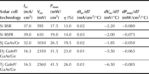
The reverse voltage behaviour of solar cells is needed for the prediction of shadowing and hot-spot phenomena on solar cell strings. Reverse-biased cells may experience excessive heating, minor permanent loss of power output, or permanent short-circuit failure [34]. Generally, single and Mj gallium arsenide solar cells are more sensitive to reverse bias than silicon cells [35] as seen in Figure 2, requiring the insertion of by-pass diodes on each cell for effective protection. Testing apparatus and procedures are similar to the EP ones, but current and power limitations are needed to avoid cell breakdown.
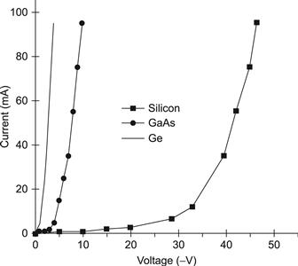
FIGURE 2 Reverse characteristics of some space solar cells.
3.1.4 Capacitance Characterisation
The dynamic behaviour of solar cells may introduce specific requirements on the subsequent solar array regulator. Therefore, the capacitance of solar cells needs to be characterised following two different methods:
• Small signal or frequency domain method: This is the measured high-frequency impedance around a certain bias point. Tests are performed with voltage biasing and in darkness [36].
• Large signal or time domain method: The rise of solar cell voltage between two operational points gives the solar cell capacitance by applying the formula C = Isc(t2 − t1)/(V2 − V1) [37], where t2, t1 and V2, V1 are the time and voltages associated with these operational points.
3.2 Environmental Tests
Environmental tests are performed to check solar array endurance to the different surroundings to which it is exposed during its complete lifetime. The most damaging environments are depicted here:
• Ground operations: Solar arrays are exposed to possible physical damage during manufacturing, integration, handling, and transportation activities. During long storage periods, solar array components maybe corroded by humidity. Tests are performed at component, solar cell, and SCA levels.
• Launch: Vibration, shocks, acceleration, and acoustic fields affect the solar array in this phase, producing high mechanical stress levels that could produce physical damage either just after testing or in orbit. Vibration, shock, and acoustic tests are performed usually at higher levels of solar array integration; panel, wing, and spacecraft level.
• Space: Particles, temperature, vacuum, and micrometeoroids are the main factors degrading solar arrays in space. Each factor affects different solar array components and interfaces. Tests are mainly conducted at solar cell, SCA level, and coupon level.
EP and visual inspection tests are performed before and after exposure of photovoltaic devices to any environmental tests. The main environments affecting solar array performance are described in the following sections in more detail.
3.2.1 Radiation Testing
The radiation environment in space basically comprises electrons and protons of different spectral energies. Solar cells are permanently damaged by these particles; displacement damage is produced in the cells’ crystalline structure, reducing the minority carrier diffusion length and lifetimes in the cells’ base region, driving a degradation of the cells’ electrical parameters. For medium- and high-radiation environment missions, solar cell particle degradation is the key parameter for solar array sizing. Cover glasses and adhesives can be darkened by radiation reducing the array performance, by transmission losses and operational temperature increases.
Two methods are followed to predict the performance of solar cells under the space radiation environment: JPL method based on reducing all proton/electron energies from a certain space environment to an equivalent normal incidence and mono-energetic irradiation, usually 1 MeV electrons [38–40] and NRL model based in the displacement damage dose methodology [41] (see Figure 3).
FIGURE 3 Power degradation of space solar cells under 1 MeV electron particles.
Solar cell radiation testing is performed on solar cell or SCAs at electron and proton irradiation facilities:
• Electrons are produced by Van der Graaff generators. Typical electron energies range from 0.6 up to 2.5 MeV and flux between 109 up to 1.5×10¹² e−/cm2/s. Cells are irradiated under vacuum or inert gas conditions.
• Low-energy protons (<2MeV) are produced by hydrogen ionising chambers and mass separators. Tandem Van der Graaff generators produced protons with energy from 2 MeV to 10 MeV and cyclotrons and synchrocyclotrons from 10 MeV to 50 MeV and 50 MeV to 155 MeV, respectively. Cells are always irradiated under vacuum conditions.
In general, the crystalline damage and performance degradation of irradiated solar cells is not stable for certain types. Recovery or further degradation phenomena are observed after annealing at temperatures higher than 20 °C and exposure to sunlight [42,43], suggesting performance of photon irradiation and annealing testing after particle irradiation.
3.2.2 Ultraviolet Radiation
Ultraviolet radiation can darken certain types of coated solar cell cover glass and adhesives, reducing the sunlight transmission to the solar cells, increasing solar array temperature and therefore lowering its EP [44]. Cracks on solar cell cover glasses may increase cell current degradation by 2% more for EOL [45]. Tests are conducted in vacuum chambers on cover glasses, SCAs, or solar array coupons, at solar cell operational temperature in orbit, using UV light sources based on xenon arc, high-pressure mercury, or halogen arc discharge lamps [46].
3.2.3 Atomic Oxygen (ATOX)
For low-Earth orbits (between 180 km and 650 km), the presence of ATOX is a main cause of erosion of silver solar cell interconnectors [47,48] and the kapton foil glued to the support structure outer layer [49]. ATOX durability testing on components or solar array coupons is performed in plasma asher chambers, being air raw material that becomes a plasma of atomic oxygen and other particles [50]. ATOX dose is determined using uncoated kapton samples whose erosion is known from flying data.
3.2.4 Thermal Cycling
The temperature cycling experienced by solar arrays in orbit (eclipses) is the cause with time of fatigue cracking of harnesses, bus-bars, interconnector material, and interconnector solder/weld joints [51], and also the cause of increased series resistance in the solar cell and interconnector interface. Temperature cycling tests are performed following two methods on either solar array coupons or SCAs:
• Vacuum: So-called thermal vacuum or vacuum thermal cycling provides a good simulation of the space environment, but not of the temperature rate decay in orbit [52].
• Ambient pressure: Fast temperature change rates are achieved with circulating inert gas chambers. Cost and test duration are considerably reduced compared to vacuum chambers, but failures tend to happen earlier than with vacuum chambers [53].
3.2.5 Vacuum
A space vacuum might vaporise metals (Mg, Cd, and Zn) and also volatile materials like adhesives. Thermal vacuum is a standard test performed at component and up to solar array level, for endurance testing of components and interfaces. Chambers as described in [52] are commonly available in the space photovoltaic industry and test houses. Failures coming from wrong manufacturing process or contamination of materials are also quickly revealed with these tests [54].
3.2.6 Micrometeoroids
More frequent impacts from micrometeoroids and space debris (between 10−6 and 10−3 g) mainly erode cover glass and solar array exposed coatings, with small solar array performance degradation due to optical losses. Predictions are in agreement with in-orbit degradation [55] and permanent loss of solar array sections by impacts on harnesses, though these are rare [56]. Hypervelocity impacts of particles are simulated with plasma drag accelerators [57,58] and light gas guns [59].
3.2.7 Electrostatic Discharge
Dielectric solar array surfaces, mainly solar cell cover glass and kapton layers, are subject to electrostatic charging due to geomagnetic substorm activity or by the spacecraft surrounding plasma. Subsequent sudden electrostatic discharge (ESD) effects may permanently damage solar array components [60]. Cover glasses are coated with conductive coatings (i.e., ITO) and grounded [61] to lighten charging and to give an equipotential surface for scientific field measurements. Tests are conducted at coupon level to check adequacy of components and interfaces [62] and at component level for the survival of the conductive coating to the mission environment [17].
3.2.8 Humidity
Accelerated humidity/temperature testing of solar cells is conducted to check the stability of solar cell contacts and anti-reflection coatings for long storage periods [63]. GaAs solar cells with AlGaAs window layers are submitted to this test in order to assure the effective protection of the antireflection coating to the corrosion of this window layer [64,65].
3.3 Physical Characteristics and Mechanical Tests
Several tests are presented in this section, not only tests to check mechanical characteristics as adhesion of coatings, contacts or interconnectors, but also measurements of some physical characteristics needed for solar array sizing or essential inputs to other solar array analysis (Mass Budget, Thermal Analysis, etc). A summary is depicted in Table 2.
TABLE 2 Mechanical/Physical Characterisation Tests on Space Solar Cells

4 Monitoring of Space Solar Cells and Arrays
4.1 Flight Experiments
Several flight experiments have been conducted with solar cells/coupons in order to verify their endurance to the space environment and ground radiation testing assessment. Most of the flight experiments measure main electrical parameters of the cells and coupons (Isc, Voc, and power at certain voltage, full I–V curve), sun aspect angle, and the operational temperature. In Table 3 some of the most relevant recent flight experiments are listed together with the publication reference, dates of data acquisition, orbit (apogee/perigee), cell/coupon types and main conclusions achieved.
TABLE 3 Summary of Flight Experiments
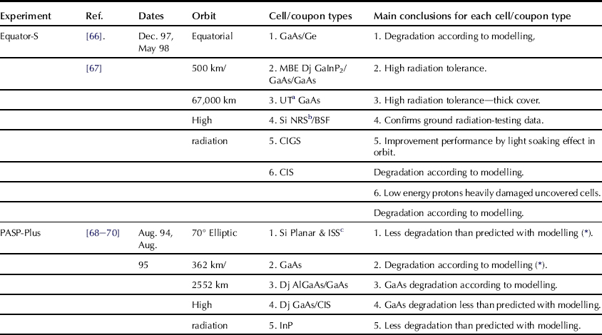
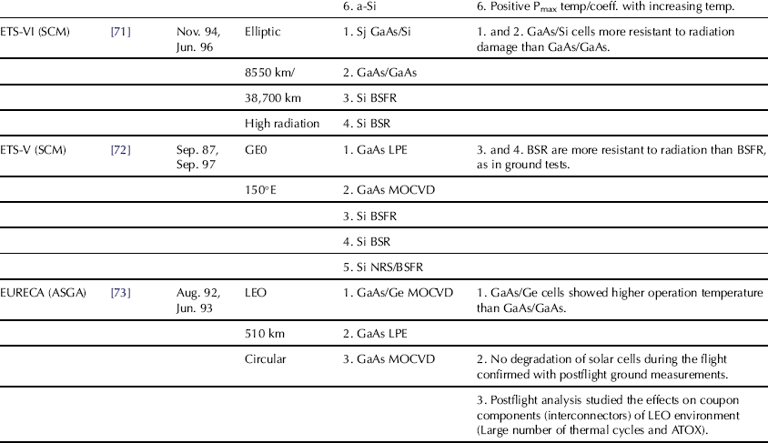
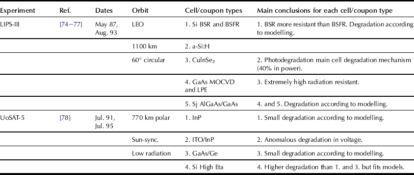
For other abbreviations and standard solar cell terms see text or Chapter Ia-1.
∗Parasitic current collected by these coupons correlates with ground testing and prediction models.
cSilicon cells of the International Space Station Array
Some flight experiments are, at the time of this writing, in preparation:
• Mars array technology experiment (MATE): Several solar cell technologies shall be sent to Mars surface for checking their performance and endurance, together with instrumentation for the Mars surface (sun spectrum, dust, temperature, etc.) characterisation [79].
• Concentrator solar cell array technology flight experiment: Assessment of the performance of reflective concentrators with Mj solar cells [80].
4.2 Monitoring of Solar Array Performance in Space
Monitoring of solar arrays in space is mainly needed to verify that their performance meets the spacecraft power requirements for planned operations and that the design performance predictions for the complete mission are met. Reliable preflight data based on ground performance measurements, solar cell qualification tests, and power budget calculations, based on qualification tests, are needed initially for an accurate performance evaluation in orbit. For flight data acquisition, temperature sensors, operational and short circuit sensors, and operational and open circuit voltage sensors are required, together with precise attitude and orbit data. Their quantity and precision drives the flight data quality [81]. Flight data are converted to standard conditions (1 Solar Constant and 25 °C) for comparison with predicted data. In-orbit performance of some recent spacecraft is shown in Table 4, which includes relevant literature references, dates of evaluated data, orbit, SA type (array layout, power and solar cell type), and main conclusions achieved.
TABLE 4 In-Orbit Performance of Recent Spacecraft

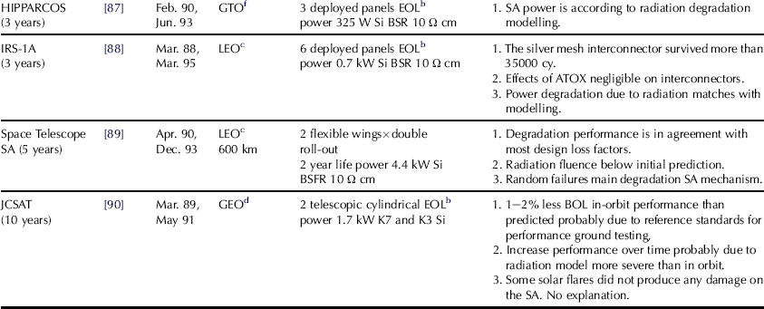
For other abbreviations and standard solar cell terms see text or Chapter Ia-1.
4.3 Spacecraft Solar Array Anomalies in Orbit
Another source of data for improving solar array design comes regrettably from anomalies experienced by spacecraft SA in orbit. Investigations of the failure mechanism in-orbit are much more complicated due to the small quantities of data often available. However, some anomalies in orbit could be acceptably explained; a few of them are depicted here in the following sections.
4.3.1 European Communication Satellite (ECS) and Maritime European Communication Satellite (MARECS)
After 1.5 years in GEO both SA (virtually identical, two wings of three rigid panels each with silicon solar cells) started to suffer partial loss of power [60]. The failures seemed to be short-circuits between the cell network and panel structure. These failures continued intermittently until the end both missions, however, for ECS the power losses were recovered. Several potential failure modes were identified: imperfections of the Kapton insulation layer or embedded particles between layers, insulation breakdown by electrostatic discharge, thermal cycling, corona effects, micrometeoroids, or a combination of all of them. None of the potential failure modes could be identified as being responsible for the ECS and MARECS anomalies; however, several weak points in the SA design were identified, investigations continued in the direction of the most probable failure mode (ESD) [91], and some improvements were proposed aiming to lower the risk of these failures: designs should be adapted to incorporate sufficient margins in areas where uncertainties exist, parallel cell strings sections instead of single-string sections, and more stringent tests in manufacturing and acceptance for early failure detection.
4.3.2 X-Ray Timing Explorer (XTE)
The XTE spacecraft was launched in December 1995. SA is composed of two wings of three rigid panels each, with silicon solar cells. Shortly after launch, the array showed discontinuous current drops, consistent with the loss of a part of a cell, when coming out from eclipse. The failure mechanism seems to be cell cracks not detected in ground inspections that became open in orbit due to the temperature gradients. These cracks were probably produced during the extensive tap tests, performed to detect SCA to substrate delaminations. During testing on the ground, following the same activities as for the flight SA, the qualification panel showed these effects, giving high confidence to this theory [92].
4.3.3 CPS Navstars 1–6
Six GPS Navstars satellites were placed in 20,000 km circular orbits from 1980. Mission lifetime for each spacecraft was five years and silicon solar cells K4 or K6 were in the SAs. After two years in orbit all spacecraft suffered an unexpected additional degradation of 2.5%. Investigations carried out in optical reflectors surfaces of one of the spacecraft revealed traces of contamination covering all spacecraft external surfaces. These contaminants mainly come from the outgassing of materials from the spacecraft, leading to reflectivity degradation of the cover glasses [93].
4.3.4 Pioneer Venus Orbiter SA
Pioneer Venus orbiter was a spin-stabilised (5 rpm) cylindrical spacecraft that operated in a high-eccentric near-polar orbit around Venus for more than eight years. After two years orbiting, power drops correlated with string losses were observed depending on the vehicle rotating angle. This suggested failures on strings due to reverse bias of cells (no shunt diodes protected the strings) produced by cyclic shadows made by the magnetometer boom cast, not predicted and unavoidable for the mission success. Ground tests were not conclusive that the cyclic reverse bias operation ended in cell breakdowns. Therefore, other interactions, as the ATOX environment in the Venus upper atmosphere, could favour the SA degradation [94].
4.4 Postflight Investigations on Returned Solar Arrays
Returned SAs from space are valuable opportunities to assess their predicted behaviour in the space environment. Few SAs have been returned to Earth and a brief summary of their investigation programmes and the major conclusions are outlined in subsequent paragraphs.
4.4.1 Hubble Space Telescope Solar Array 1
One wing of the Hubble Space Telescope SA was retrieved from space in December 1993, after more than 3.5 years operating in a low-Earth orbit, The SA of the Hubble Space Telescope consisted of two wings of a double roll-out concept using two flexible solar cell blankets on each wing. The 48760 Silicon BSFR solar cells should provide the required 4.4 kW after two years in operation.
The postflight investigation programme carried out between 1994 and 1995 [95] had the following main objectives:
• Assess the effect of different LEO interaction and environments as: thermal fatigue, ATOX, meteoroid and space debris damage, contaminations, UV, etc.
During the investigation programme the SA was submitted to several tests like detailed visual inspections, EP and health checks, wipe testing, etc. The SA mechanisms were also mechanically tested to study their deploy/retract performance, and finally the SA was totally disassembled for detailed investigation of all its components.
The main conclusions of the postflight investigation programme related to the SA blankets are the following:
• SA performance: 5% more power than predicted after 3.6 years in orbit, despite several anomalies (string shorts) that reduced the power by 6.7%. Random failures are the main contributors to SA degradation. SA overall degradation excluding failures was less than predicted, mainly as radiation model used was pessimistic.
• Solar cell interconnectors: No fatigue effects on interconnection loops were detected as expected from preflight qualification data.
• Harness: Fatigue effects were evident on flexible data harnesses, but no full detachments were found.
• Adhesives for ATOX protection: Darkening due to UV could increase SA operational temperature.
• Micrometeoroids: More than 4000 impacts were detected on the SA, but none of them produced permanent short circuits. The loss factor applied in the design is in full agreement with the results of the observed degradation (1.8%).
4.4.2 EURECA
The European Retrievable Carrier (EURECA) was launched in July 1992 (500-km orbit) and completely retrieved in July 1993 by the Space Shuttle. The SA consists of two interchangeable wings of five rigid panels (~100 m2) each providing initially 5 kW. Silicon BSFR 10-Ω cm solar cells of two sizes were used to manufacture the charge and load array networks. The solar array postflight investigation programme had the objectives of studying LEO environment effects and mainly the anomalies faced during the mission [96]. Main conclusions are depicted here:
• Failures by fatigue (inadequate bend radii in the stress relief loop) in the Wiring Collecting Panels (WCPs) were responsible for open circuits on solar cell strings. WPCs were never tested in a flight representative configuration, as it was not possible to detect in advance the weakness of this design.
• A short-circuit on the load array produced current from the battery during eclipse to the solar array (no blocking diodes were placed between the SA and battery circuits). A large burn mark was found at the suspected location of the short circuit after retrieval.
• Kapton FEP (Fluorinated Ethylene-Propylene) coatings of the cable insulations were completely eroded in X-ray/UV direction.
• The exposed side of MoAg interconnectors was oxidised and eroded by ATOX.
• Adhesives for ATOX protection were also darkened (top surfaces converted to SiO2) and all surfaces investigated showed contamination of carbon or silicone.
4.4.3 MIR Solar Array
In January 1998, a segment of the MIR solar array was retrieved by the space shuttle. The segment, composed of eight panels, spent 10.5 years in a 380 km orbit. The panel design is exclusive; a laminated sandwich of cover glass, glass cloth, silicon solar cells (11% efficiency), glass cloth and optical solar reflectors (OSRs) [97]. Two postflight investigation programmes have been conducted in the USA and Russia. The main conclusions are the following:
• Hot spots are the main reason for the 50% power degradation of the solar array. By-pass diodes were not installed on the panel, relying especially on solar cell screening for handling full reverse currents. High temperatures during the hot spots destroyed separate commutation bundles in the circuits of serial connected solar cells [98,99].
• Large SiOx contaminations were found on all exposed surfaces of the panel, due to outgassing of silicone adhesives, resulting in a total power loss of only 0.72%.
• The meteoroid and space debris impact produced less than 1% power loss.
• The temperature increase over life was 7 °C, due to an increase of the emittance and decrease of the absorptance.
• Solar cells not influenced by the hot spots had only 10–15% power degradation.
Acknowledgements
To my wife, Maria Jesus, for her constant support and patience. My colleagues C. Signorini and R. Crabb (ESA-Estec) and T. J. Gomez (Spasolab) for their good advice and helpful comments about the contents of this chapter. All my colleagues at Estec, especially of the solar generator section, Spasolab and the space photovoltaic community for fruitful discussions about these subjects. I am grateful to ESA for its support and permission to publish this work.
References
1. ISO/DIS 15387: Space Systems—Single-Junction Space Solar Cells—Measurement and Calibration Procedures.
2. Anspaugh BE, et al. Results of the 2001 JPL balloon flight solar cell calibration program. JPL Publication 02–004 2002;.
3. Pichetto V, et al. Casolba calibration of solar cells using balloon flight. In: Proceeding of the 29th IEEE Photovoltaic Specialists Conference. 2002; New Orleans.
4. Roussel M, et al. Calibration de cellules solaires hors atmosphère. In: Proceeding of the 4th European Space Power Conference, ESA SP-210. 1984;:257–264. .
5. Jenkins P, et al. Uncertainty analysis of high altitude aircraft air mass zero solar cell calibration. In: Proceeding of the 26th IEEE Photovoltaic Specialists Conference. 1997;:857–860. Anaheim.
6. Suppa EG. Space Calibration of solar cells Results of 2 shuttle flight missions. In: Proceeding of the 17th IEEE Photovoltaic Specialists Conference. 1984;:301–305. Orlando.
7. Landis GA, et al. Calibration and measurement of solar cells on the international space station: A new test facility. In: Proceeding of the 36th Intersociety Energy Conversion Conference. 2001;:229–231. .
8. Davies MAH, Goodbody C. The calibration of solar cells in terrestrial sunlight. In: Proceeding of the 2nd European Space Power Conference, ESA SP-320. 1991;:583–587. .
9. Garcia-Cervantes L, et al. Ground level sunlight calibration of space solar cells. In: Proceeding of the 5th European Space Power Conference, ESA SP-416. 1998;:615–620. .
10. Garcia L, et al. Uncertainty analysis for ground level sunlight calibration of space solar cells at Tenerife. In: Proceeding of the 17th European Photovoltaics Solar Energy Conference. 2001;2259–2262. Munich.
11. Yiqiang Y, et al. Calibration of AM0 reference solar cells using direct normal terrestrial sunlight. In: Proceeding of the 9th Asia/Pacific Photovoltaic Science and Engineering Conference. 1996.
12. Kawasaki O, et al. Study of solar simulator method and round robin calibration plan of primary standard solar cell for space use. In: Proceeding of the 1st World Conference on Photovoltaic Energy Conversion. 1994; Hawaii.
13. Metzdorf J, et al. Absolute indoor calibration of large area solar cells. In: Proceeding of the 5th European Sympousium on Photovoltaic Generators in Space, ESA SP-267. 1986;397–402.
14. ASTM E973M-96, Test method for determination of the spectral mismatch parameter between a Photovoltaic device and a Photovoltaic reference cell.
15. Gras A, et al. Terrestrial secondary calibration analysis. In: Proceeding of the 16th European Space Power Conference. 2000;1011–1014.
16. Gras A, et al. Generic test procedure for solar cell testing. In: Proceeding of the 3rd European Space Power Conference, ESA WPP-054. 1993;743–748.
17. ESAPSS-01–604. Generic specification for silicon solar cells. 1988.
18. Seaman CH, et al. The spectral irradiance of some solar simulators and its effect on cell measurements. In: Proceeding of the 14th IEEE Photovoltaic Specialists Conference. 1980;494–499. San Diego.
19. Goodelle GS, et al. Simulator spectral characterization using balloon calibrated solar cells with narrow band pass filters. In: Proceeding of the 15th IEEE Photovoltaic Specialists Conference. 1981;211–217. Orlando.
20. Thrum T, et al. Characterizing state of the art solar panels—A new approach for large area testing. In: Proceeding of the 28th IEEE Photovoltaic Specialists Conference. 2000;1320–1323. Anchorage.
21. Kilmer LC. A more accurate, higher fidelity dual source AM0 solar simulator design. In: Proceeding of the 4th European Space Power Conference, ESA SP-369. 1995;671–675.
22. Sturcbecher JJ, et al. The mini-flasher: a solar array test system. Sol Energy Mater Sol Cells. 1994;36:91–98.
23. Lukschal W, et al. A pulsed solar simulator for electrical performance tests of space solar cells/arrays. In: Proceeding of the 1st European Space Power Conference, ESA SP-294. 1989;689–693.
24. Granata JE, et al. Triple-junction GaInP2/GaAs/Ge solar cells, production status, qualification results and operational benefits. In: Proceeding of the 28th IEEE Photovoltaics Specialists Conference. 2000;1181–1184. Anchorage.
25. Gras A, et al. Analysis for multi-junction solar cell measurements at Spasolab. In: Proceeding of the 6th European Space Power Conference, ESA SP-502. 2002;577–580.
26. Emery K, et al. Procedures for evaluating multi-junction concentrators. In: Proceeding of the 28th IEEE Photovoltaic Specialists Conference. 2000;1126–1130. Anchorage.
27. Rauschenbach HS. Solar Cell Array Design Handbook. Litton Educational Publishing 1980.
28. Adelhelm R, et al. Matching of multi-junction solar cells for solar array production. In: Proceeding of the 28th IEEE Photovoltaic Specialists Conference. 2000;1336–1339. Anchorage.
29. King DL, et al. Temperature coefficients for PV modules and arrays: Measurement methods, difficulties and results. In: Proceeding of the 26th IEEE Photovoltaic Specialists Conference. 1997;1183–1186. Anaheim.
30. Adelhelm R, et al. Temperature coefficients of tandem solar cells under appropriate spectra. In: Proceeding of the 14th European Photovoltaics Solar Energy Conference. 1997; Barcelona.
31. Burger DR, et al. Angle of incidence corrections for GaAs/Ge solar cells with low absorptance coverglass. In: Proceeding of the 25th IEEE Photovoltaic Specialists Conference. 1996;243–246. Washington DC.
32. Larue JC. Pulsed measurement of solar cell spectral response. In: Proceeding of the 2nd European Photovoltaic Solar Energy Conference. 1979;477–486. West Berlin.
33. King DL, et al. New methods for measuring performance of monolithic Mj solar cells. In: Proceeding of the 28th IEEE Photovoltaic Specialists Conference. 2000;1197–1201. Anchorage.
34. Rauschenbach HS, et al. Breakdown phenomena on reverse biased silicon solar cells. In: Proceeding of the 9th IEEE Photovoltaic Specialists Conference. 1972;217–225. Silver Springs.
35. Baron WR, et al. GaAs solar cell reverse characteristics. In: Proceeding of the 19th IEEE Photovoltaic Specialists Conference. 1987;457–462. New Orleans.
36. Schwander D. Dynamic solar cell measurement techniques: new small signal measurement techniques. In: Proceeding of the 6th European Space Power Conference, ESA SP-502. 2002;603–608.
37. Rueda P, et al. Mj GaAs solar cell capacitance and its impact upon solar array regulators. In: Proceeding of the 6th European Space Power Conference, ESA SP-502. 2002;29–34.
38. Tada HY, et al. The Solar Cell Radiation Handbook. JPL publication 1982; pp. 82–69.
39. Anspaugh BE. GaAs Solar Cell Radiation Handbook. JPL publication 1996; pp. 96–9.
40. Marvin DC. Assessment of Mj solar cell performance in radiation environments Aerospace Report TOR-2000(1210)-1. The Aerospace Corporation 2000.
41. Walters RJ, et al. Analysis and modelling of the radiation response of Mj space solar cells. In: Proceeding of the 28th IEEE Photovoltaic Specialists Conference. 2000;1092–1097. Anchorage.
42. Crabb R. Photon induced degradation of electron and proton irradiated silicon solar cells. In: Proceeding of the 10th IEEE Photovoltaic Specialists Conference. 1973;396–403. Palo Alto.
43. Fischer H, et al. Investigation of photon and thermal induced changes in silicon solar cells. In: Proceeding of the 10th IEEE Photovoltaic Specialists Conference. 1973;404–411. Palo Alto.
44. Goodelle GS, et al. High vacuum UV test of improved efficiency solar cells. In: Proceeding of the 11th IEEE Photovoltaic Specialists Conference. 1975;184–189. Scottsdale.
45. Meulenberg A, et al. Evidence for enhanced UV degradation to cracked coverslides. XV Space Photovoltaic Research and Technology 1997;213–218.
46. Matcham J, et al. Effects of simulated solar-UV radiation on solar cell efficiency and transparent cell components. In: Proceeding of the 5th European Space Power Conference, ESA SP-416. 1998;643–650.
47. Gerlach L, et al. Advanced solar generator technology for the Eureca low earth orbit. In: Proceeding of the 18th IEEE Photovoltaic Specialists Conference. 1985;78–83. Las Vegas.
48. Dunnet A, et al. Assessment of ATOX erosion of silver interconnects on Intelsat VI F3. In: Proceeding of the 2nd European Space Power Conference, ESASP-320. 1991;701–706.
49. Banks BA, et al. Protection of solar array blankets from attack by low earth orbital atomic oxygen. In: Proceeding of the 18th IEEE Photovoltaic Specialists Conference. 1985;381–386. Las Vegas.
50. Ruthledge SK, et al. Atomic oxygen effects on SiOx coated kapton for photovoltaic arrays in low earth orbit. In: Proceeding of the 22nd IEEE Photovoltaic Specialists Conference. 1991;1544–1547. Las Vegas.
51. Richard D. A rational approach to design and test a space photovoltaic generator. In: Proceeding of the 15th IEEE Photovoltaic Specialists Conference. 1981;554–559. Orlando.
52. Ley W. DFVLR facility for thermal cycling tests on solar cells panel samples under vacuum conditions. In: Proceeding of the 12th IEEE Photovoltaic Specialists Conference. 1976;406–412. Baton Rouge.
53. Larue JC, et al. Accelerated thermal cycling of solar array samples. In: Proceeding of the 1st European Symposium on Photovoltaic Generators in Space, ESASP-140. 1978;57–64.
54. Norris Blake III L. Lessons learned about fabrication of space solar arrays from thermal cycle failures. In: Proceeding of the 25th IEEE Photovoltaic Specialists Conference. 1996;329–332. Washington DC.
55. Gerlach L, et al. HST-SA1: electrical performance evaluation. Hubble Space Telescope Solar Array Workshop, ESA WPP-77 1995;257–264.
56. Murray JF, et al. Space environment effects on a rigid panel solar array. In: Proceeding of the 22nd IEEE Photovoltaic Specialists Conference. 1991;1540–1543. Las Vegas.
57. Paul KG, et al. Post-Flight particle impacts on HST solar cells. Hubble Space Telescope Solar Array Workshop, ESA WPP-77 1995;493–500.
58. Brandhorst Jr HW, et al. Hypervelocity impact testing of stretched lens array modules. In: Proceeding of the 6th European Space Power Conference, ESA SP-502. 2002;585–590.
59. Schneider E. Micrometeorite impact on solar panels. In: Proceeding of the 5th European Symposium on Photovoltaic Generators in Space, ESA SP-267. 1986;171–174.
60. Bogus K, et al. Investigations and conclusions on the ECS Solar Array in orbit power anomalies. In: Proceeding of the 18th IEEE Photovoltaic Specialists Conference. 1985;368–375. Las Vegas.
61. Stern TG, et al. Development of an electrostatically clean solar array panel. In: Proceeding of the 28th IEEE Photovoltaic Specialists Conference. 2000;1348–1351. Anchorage.
62. Bogorad A, et al. Electrostatic discharge induced degradation of solar arrays. In: Proceeding of the 22nd IEEE Photovoltaic Specialists Conference. 1991;1531–1534. Las Vegas.
63. Bishop CJ. The fundamental mechanism of humidity degradation in silver-titanium contacts. In: Proceeding of the 8th IEEE Photovoltaic Specialists Conference. 1970;51–61. Seattle.
64. Iles PA, et al. The role of the AlGaAs window layer in GaAs heteroface solar cells. In: Proceeding of the 18th IEEE Photovoltaic Specialists Conference. 1985;304–309. Las Vegas.
65. Mitsui K, et al. A high quality AR coating for AlGaAs/GaAs solar cells. In: Proceeding of the 17th IEEE Photovoltaic Specialists Conference. 1984;106–110. Orlando.
66. La Roche G, et al. Evaluation of the flight data of the Equator-S mini-modules. In: Proceeding of the 16th European Photovoltaic Solar Energy Conference. 2000;945–950. Glasgow.
67. Messenger SR, et al. A displacement damage dose analysis of the Comets and Equator-S space solar cell experiments. In: Proceeding of the 16th European Photovoltaic Solar Energy Conference. 2000;974–977. Glasgow.
68. Curtis H, et al. Final results from the PASP-Plus flight experiment. In: Proceeding of the 25th IEEE Photovoltaic Specialists Conference. 1996;195–198. Washington DC.
69. Davis VA, et al. Parasitic current collection by PASP PLUS solar arrays. XIV Space Photovoltaic Research and Technology, NASA CP-10180 1995;274–285.
70. Guidice DA. High voltage space-plasma interactions measured on the PASP Plus test arrays. XIV Space Photovoltaic Research and Technology, NASA CP-10180 1995;286–295.
71. Imaizumi M, et al. Flight degradation data of GaAs-on-Si solar cells mounted on highly irradiated ETS-VI. In: Proceeding of the 28th IEEE Photovoltaic Specialists Conference. 2000;1075–1078. Anchorage.
72. Aburaya T, et al. Analysis of 10 years’ flight data of solar cell monitor on ETS-V. Sol Energy Mater Sol Cells. 2001;68:15–22.
73. Flores C, et al. Post-flight investigation of the ASGA solar cell experiment on Eureca. In: Proceeding of the 1st World Conference on Photovoltaic Energy Conversion. 1994;2076–2081. Hawaii.
74. Burgess RM, et al. Performance analysis of CulnSe2 and GaAs solar cells aboard the LIPS-III flight Boeing lightweight panel. In: Proceeding of the 23rd IEEE Photovoltaic Specialists Conference. 1993;1465–1468. Louisville.
75. Woodyard JR, et al. Analysis of LIPS-III satellite a-Si:H alloy solar cell data. In: Proceeding of the 25th IEEE Photovoltaic Specialists Conference. 1996;263–266. Washington DC.
76. Severns JG, et al. LIPS-III A solar cell test bed in space. In: Proceeding of the 20th IEEE Photovoltaic Specialists Conference. 1988;801–807. Las Vegas.
77. Kulms H, et al. Results of the MBB LIPS-III experiment. In: Proceeding of the 21st IEEE Photovoltaic Specialists Conference. 1990;1159–1163. Orlando.
78. Goodbody C, et al. The UoSAT-5 solar cell experiment—Over 4 years in orbit. In: Proceeding of the 25th IEEE Photovoltaic Specialists Conference. 1996;235–238. Washington DC.
79. Scheiman DA, et al. Mars array technology experiment (MATE). In: Proceeding of the 28th IEEE Photovoltaic Specialists Conference. 2000;1362–1365. Anchorage.
80. Jain JK, et al. Concentrator solar array technology flight experiment. In: Proceeding of the 29th IEEE Photovoltaic Specialists Conference. 2002;1362–1365. New Orleans.
81. Bogus K, et al. Comparative evaluation of the in-orbit performance of ESA’s satellite solar generators. In: Proceeding of the 3rd European Space Power Conference, ESA WPP-054. 1993;529–535.
82. Rumler P, et al. SOHO power system performance during 6 years in orbit. In: Proceeding of the 6th European Space Power Conference, ESA SP-502. 2002;141–146.
83. Jalinat A, et al. In orbit behaviour of SPOT 1,2 and 3 solar arrays. In: Proceeding of the 5th European Space Power Conference, ESA SP-416. 1998;627–631.
84. Fodor JS, et al. In-orbit performance of Hughes HS 601 solar arrays. In: Proceeding of the 2nd World Conference on Photovoltaic Energy Conversion. 1998;3530–3533. Vienna.
85. Ozkul A, et al. In-orbit performance characteristics of Intelsat-V solar arrays. In: Proceeding of the 1st World Conference on Photovoltaic Energy Conversion. 1994;pp.1994–1997. Hawaii.
86. Takata N, et al. In-orbit performance of CS-3A spacecraft GaAs solar array. In: Proceeding of the 1st European Space Power Conference, ESA SP-294. 1989;823–828.
87. Crabb RL, Robben AP. In-flight Hipparcos solar array performance degradation after three and a half years in GTO. In: Proceeding of the 3rd European Space Power Conference, ESA WPP-054. 1993;541–549.
88. Puthanveettil SE, et al. IRS-1A Solar array—in-orbit performance. In: Proceeding of the 4th European Space Power Conference, ESA SP-369. 1995;583–585.
89. Gerlach L, et al. Hubble Space Telescope and EURECA solar generators a summary of the post flight investigations. In: Proceeding of the 4th European Space Power Conference, ESA SP-369. 1995;5–20.
90. Gelb SW, et al. In-orbit performance of Hughes HS 393 solar arrays. In: Proceeding of the 22nd IEEE Photovoltaic Specialists Conference. 1991;1429–1433. Las Vegas.
91. Levy L, et al. MARECS & ECS anomalies: attempt for insulation defect production in kapton. In: Proceeding of the 5th European Symposium on Photovoltaic Generators in Space, ESASP-267. 1986;161–169.
92. Gaddy EM, et al. The Rossi X-Ray timing explorer XTE solar array anomaly. XV Space Photovoltaic Research and Technology 1997;144–153.
93. Marvin DC, et al. Anomalous solar array performance on GPS. In: Proceeding of the 20th IEEE Photovoltaic Specialists Conference. 1988;913–917.
94. Goldhammer LJ, et al. Flight performance of the Pioneer Venus orbiter solar array. In: Proceeding of the 19th IEEE Photovoltaic Specialists Conference. 1987;494–499. New Orleans.
95. Proceedings of the Hubble Space Telescope SA workshop. ESA WPP-77, 1995.
96. EURECA The European retrievable carrier, Technical Report ESA WPP-069, 1994.
97. Pinkerton RJ. MIR returned solar array. In: Proceeding of the 36th Intersociety Energy Conversion Conference. 2001;217–222.
98. Letin VA. Optical, radiation and thermal cycling losses of power solar array returned from orbital station MIR after 10.5 years of operation. In: Proceeding of the 6th European Space Power Conference, ESA SP-502. 2002; pp. 7.13–718.
99. Grabov AB, et al. A terrestrial investigation of material’s degradation mechanisms in silicon solar cells, which returned from MIR space station after ten years exploitation. In: Proceeding of the 6th European Space Power Conference, ESA SP-502. 2002;733–740.