
13.1 NATURAL NUMBERS
Let Y be an n-bit positive number and X a natural number belonging to the range 0 ≤ X < Y, so that it can also be represented as an n-bit number. The circuit corresponding to the basic division algorithm 6.1 (with q(i) substituted by q(p − i) in order that the least significant bit of q be q(0)) is an iterative circuit made up of p cells, which implement the division_step procedure (Figure 13.1). The divider structure is shown in Figure 13.2 (combinational and sequential implementations). In the binary case the division_step block (base-2 division step, Algorithm 6.2) consists of an (n + 1)-bit subtractor and an n-bit 2-to-1 multiplexer (Figure 13.1). The corresponding cost C(n, p) and computation time T(n, p) are equal to
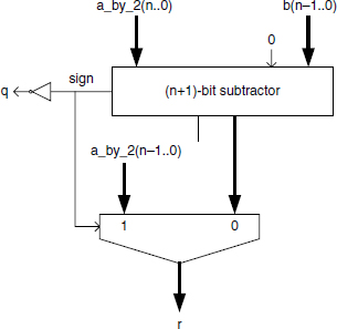
Figure 13.1 Basic cell of a binary restoring divider.
and
Example 13.1 (Complete VHDL source code available.) Generate a generic n-bits base-2 restoring divider. The division step of Figure 13.1 is:
entity restoring_cell is
port (
  a_by_2: in STD_LOGIC_VECTOR (N downto 0);
  b: in STD_LOGIC_VECTOR (N-1 downto 0);
  q: out STD_LOGIC;
  r: out STD_LOGIC_VECTOR (N-1 downto 0)
);
end restoring_cell;

architecture cel_arch of restoring_cell is
signal subst: STD_LOGIC_VECTOR (N downto 0);
begin
  subst <= a_by_2 - b;
  multiplexer: process (a_by_2,b,subst)
begin
  if subst(N)=‘1’ then r<=a_by_2(N-1 downto 0);
  else r<=subst(N-1 downto 0);
  end if;
 end process;
 q<=not subst(N);
end cel_arch;

Figure 13.2 Divider structure.
The divider structure of Figure 13.2 is:
entity div_rest_frac is
port (
  X: in STD_LOGIC_VECTOR (N-1 downto 0);
  Y: in STD_LOGIC_VECTOR (N-1 downto 0);
  Q: out STD_LOGIC_VECTOR (P-1 downto 0);
  R: out STD_LOGIC_VECTOR (N-1 downto 0)
);
end div_rest_frac;

architecture div_arch of div_rest_frac is
type connect is array (0 to P-1) of STD_LOGIC_VECTOR (N downto
0);
Signal rem_in, rem_out: connect;
begin
  rem_in(0)<=X&‘0’;
  divisor: for i in 0 to P-1 generate
    rest_cell: restoring_cell port map (rem_in(i),
               Y, Q(P-i-1), rem_out(i)(N-1 downto 0));
    rem_in(i+1)<=rem_out(i)(N-1 downto 0)&‘0’;
  end generate;

  R<=rem_out(P-1)(N-1 downto 0);
end div_arch;
Given an m-bit natural X and an n-bit positive integer Y, that is,
![]()
synthesize an integer divider, that is, a circuit generating two natural numbers Q and R such that
![]()
For that purpose (Section 6.1) Y must be substituted by Y′ = 2m.Y. Then the division of X by Y′ is computed with an accuracy of m bits, so that
![]()
and
![]()
A better option (Comment 6.1) is to substitute X by X′ = X/2 and Y by Y′ = 2m−1.Y. The final remainder R′ is divided by 2m−1. The corresponding circuit is shown in Figure 13.3.
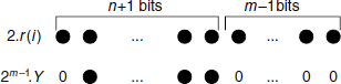
Observe that, at each step, the difference between an (m + n)-bit number (twice the previous remainder) and Y.2m−1 is computed (Figure 13.4), so that the number of bits of the internal subtractor is n + 1 (not n + m) as the m − 1 least significant bits of 2.r(i) are just propagated to the cell output.
Example 13.2 (Complete VHDL source code available.) Generate a generic m-bit by n-bit base-2 integer divider. The basic cell is the same as before (Figure 13.1).

Figure 13.3 Integer divider for natural operands.
The VHDL model is based on Figure 13.3, taking into account the observation of Figure 13.4.
entity div_rest_nat is
port (
  X: in STD_LOGIC_VECTOR (M-1 downto 0);
  Y: in STD_LOGIC_VECTOR (N-1 downto 0);
  Q: out STD_LOGIC_VECTOR (M-1 downto 0);
  R: out STD_LOGIC_VECTOR (N-1 downto 0)
);
end div_rest_nat;
architecture div_arch of div_rest_nat is
type connect is array (0 to M-1) of STD_LOGIC_VECTOR (N
downto 0);
signal wires_in, wires_out: connect;
signal zeros: STD_LOGIC_VECTOR (N-1 downto 0);
begin
  zeros<=(others=>‘0’);
  wires_in(0)<=zeros&X(M-1);
  divisor: for i in 0 to M-1 generate
    rest_cell: restoring_cell port map (wires_in(i),
                Y, Q(M-i-1), wires_out(i)(N-1 downto 0));
  end generate;
  wires_conections: for i in 0 to M-2 generate
    wires_in(i+1)<=wires_out(i)(N-1 downto 0)&X(M-i-2);
  end generate;
  R<=wires_out(M-1)(N-1 downto 0);
end div_arch;
In non binary cases the division_step block is more complex. The base-B division step described in Algorithm 6.3 consists of checking increasing values of the quotient-digit q up to the minimum value verifying
where B.a and b are the shifted remainder and the divisor, respectively; if qmin is the minimum value of q verifying (13.3), then qmin−1 is the asserted quotient-digit. This method is easy but quite ineffective. The restoring base-B division step described by Algorithm 6.4 is faster because only one value of q has to be checked at every step. The corresponding circuit is shown in Figure 13.5. It includes a 5-input 2-output look-up table, an (n × 1)-digit multiplier, an (n + 1)-digit subtractor, an n-digit adder, and (n + 1) 2-to-1 multiplexers. As far as B is greater than 2, the n-digit adder may not be replaced by a direct connection of a to the inputs 1 of the (n + 1) 2-to-1 multiplexers; in this case the restoring process doesn't actually restore the previous remainder, but consists of adding one divisor to a negative new remainder. The adding stage could be nevertheless eliminated if two subtractions are executed in parallel (−qt.b and −(qt − 1).b); then the multiplexers would select the correct remainder according to the sign of the result. This would provide a saving in cycle time, without significantly increasing the hardware cost.

Figure 13.5 Basic cell of a nonbinary divider.
The cost and the computation time of the corresponding divider are, respectively,
and
Example 13.3 (Complete VHDL source code available.) Generate a generic n-digits base-B restoring divider. The division step of Figure 13.5 is:
entity rest_baseB_step is
port (
  a: in digit_vector(N-1 downto 0);
  b: in digit_vector(N-1 downto 0);
  q: out digit;
  r: out digit_vector(N-1 downto 0)
);
end rest_baseB_step;

architecture behavioral of rest_baseB_step is
signal at: digit_vector(2 downto 0);
signal bt: digit_vector(1 downto 0);
signal qt, qt_1: digit;
signal q_x_b, a_x_B, re, r_plus_b: digit_vector(N downto 0);
signal sign: bit;
begin
  at<=a(N-1 downto N-3);
  bt<=b(N-1 downto N-2);
  a_x_B(N downto 1)<=a; a_x_B(0)<=0;
  LUT: look_up_table port map(at, bt, qt, qt_1);
  mult: base_b_mult port map(qt, B, q_x_b);
  subt: base_b_subt port map(a_x_B, q_x_b, re, sign);
  adder: base_b_adder port map(re(N-1 downto 0), B, r_plus_b);
  multiplexers: process (sign,qt_1, qt, r_plus_b,re)
  begin
    if sign=‘1’ then
      q<=qt_1; r<=r_plus_b(N-1 downto 0);
    else q<=qt; r<=re(N-1 downto 0);
   end if;
  end process;
end behavioral;
The divider structure is:
entity div_rest_baseB is
port (
  A: in digit_vector(N-1 downto 0);
  B: in digit_vector(N-1 downto 0);
  Q: out digit_vector(P-1 downto 0);
  R: out digit_vector(N-1 downto 0)
);
end div_rest_baseB;

architecture div_arch of div_rest_baseB is
type connections is array (0 to P) of digit_vector(N-1
downto 0);
Signal wires: connections;
begin
  wires(0)<=A;
  divisor: for i in 0 to P-1 generate
  rest_step: rest_baseB_step port map (wires(i),
   B, Q(P-i-1), wires(i+1));
  end generate;
  R<=wires(P)(N-1 downto 0);
end div_arch;