A Frameless Turntable |
Alys Holden |
Turntables traditionally challenge theater technicians in several ways. Cutting circles out of 4×8 sheet goods is expensive: framing becomes a morass of angles: construction is slow and complicated: and turntables are difficult to modify for reuse. A production of Beaux’ Stratagem at the Yale Repertory Theatre called for a 20′-diameter turntable to be built as inexpensively as possible while minimizing deck height for front-row sightlines. We ended up with the frameless laminated-plywood turntable this article describes. This design offered several advantages over framed and laminated-plywood turntables: the segments we developed minimized plywood waste: the turntable could be easily recycled into any diameter under 20′: and the construction was simplified by the modular design.

FIGURE 1: OVERVIEW OF THE TURNTABLE DESIGN
The turntable consisted of a pivot disk surrounded by a twenty-segment ring, each segment a two-layer lamination of ⅜″ plywood wedges. To eliminate framing, the sides of the top and bottom wedges in each segment were offset to provide a 2″ overlap joint, and the inside ends of the segments were joined to the laminated ¾″ plywood pivot disk through a similar overlap. In designing the overlap joints, we discovered that by making the pivot disk 4′−6″ rather than 4′−0′ in diameter we were able to cut two wedges — a complete ring segment — from a single sheet of plywood. Figure 1 offers a general view of the turntable.

FIGURE 2: PLYWOOD PANEL LAYOUT
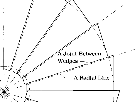
If you’ve designed turntables yourself, you may be asking, “How could the overlap between adjacent segments be constant? Doesn’t rotating one layer of wedges result in a tapered overlap between segments?” The answer, of course, is “Yes.” But we did not rotate any wedges. Instead, we translated each wedge in the upper layer of the ring 2″ relative to its mate in the lower layer, keeping the factory edges of both wedges parallel. Figure 3 illustrates the resulting layout and also shows that the joints between wedges did not lie along the turntable’s radii. Figure 4 more fully illustrates ring segment and pivot disk design.

FIGURE 3: DISK RADII & WEDGE LAYOUT
CONSTRUCTION
First, we cut 40 identical wedges from 20 sheets of ¾″ plywood. To allow “good luck” we were careful to cut each wedge ¼″ thinner than was theoretically necessary. Next, deliberately leaving a narrow gap at each joint, we laid 20 of the wedges out on the shop floor (as in Figure 3) and tacked them down. We then routed this ratchet-shaped sub-assembly into a ring with a 10′ outside radius and a 2′-4″ inside radius. We filled the center of the ring with a disk made from two pieces of ¾″ plywood cut as semicircles.
Next, we laid out the remaining 20 wedges on top of the first 20 and, after careful adjustment to provide the consistent offsets, we laminated each wedge in the second layer to the wedge below. That done, we routed the new layer into a ring with outside and inside radii of 9′−10″ and 2′−1½″, respectively. The smaller outside diameter of this ring would accommodate our chain-wrap friction drive. We cut the plywood for the disk in the center of the new ring and laminated it to the disk in the center of the first ring. While we had the turntable laid out upside down, we added plywood sweeps along its circumference to form a drive-chain channel (visible in Figure 1), laid out the caster pattern, and drilled holes for bolt connections in the ends of the segment overlaps.

FIGURE 4: TYPICAL SEGMENT AND PIVOT DISK
Finally, we pried the turntable off the floor and attached the casters with 2½″ flat head stove bolts. Caster connection was complicated by the overlap of the joints. Ideally, each side of a joint should be supported, but we wanted to attach casters to only one side of each joint. We decided to top each caster with a plate of 2″ × ⅛″ steel flat stock cut long enough to extend under the non-cast-ered side of a given joint. See Figure 5.

FIGURE 5: SECTION THROUGH DISK @ JOINT

FIGURE 6: PIVOT DETAIL (SECTION VIEW)
LOAD-IN
Except for the last segment, the ring assembled quickly because of the “good luck” gaps we had left between its segments. The last piece was still a tight fit, but brute force finally won the day. We screwed the segments together through the overlaps and added a single bolt at the ends of each overlap — a step that, in hindsight, may not have been necessary. Next, we sleeved the pipe of the pivot disk into its floor-mounted flange block. See Figure 6. Finally, we screwed the pivot disk to the ring and top-skinned the turntable with ½″ Celotef® and ⅜″ Medite®.
NOTES
For turntables with diameters smaller than 16′, a pivot disk may be optional, but having a solid structure at the center of a turntable is nearly always desirable. In all, we used 26 sheets of plywood in the rings, pivot disk, and drive channel that make up this turntable. On the other hand, that’s all we used: the turntable needed no framing, and an ordinary bolt was its most sophisticated piece of hardware. The 2″ overlap made the turntable acceptably stiff — though a second time around I would make it a 3″ overlap. I’d also use heavier duty casters than load analysis might suggest: loading conditions change as a production is rehearsed, and caster noise is a trifling difficulty compared to changing out a caster after techs begin.
