Rob Kovarik |
Whalers — Low-Profile Stiffeners for Steel-Framed Flats |
The set for a Yale School of Drama production of The Golem included two hard-covered wall sections, both 32′-0″ wide. One of them was 16′ tall and was dead hung 12′ off the deck. The other was 12′ tall and designed to fly just downstage of the first. To minimize the wall sections’ weight we framed the flats with 1″ × 0.065″ square tube. To keep the assembled walls as flat and as thin as possible, we stiffened them with whalers — steel versions of a hogs trough. As tube steel framing has become more common, theater shops the world over have developed their own styles of whalers. Those we used for The Golem are detailed in Figure 1.

FIGURE 1: THE GOLEM WHALER
Whalers like these have two components — the stiffeners and the tabs that hold the stiffeners to the assembled flats. For stiffeners, we cut ![]() bar stock to lengths dictated by the wall design. We then drilled
bar stock to lengths dictated by the wall design. We then drilled ![]() holes through the stiffeners wherever the stiffeners would cross the flat frames. Next, we made one tab for each stiffener hole by cutting
holes through the stiffeners wherever the stiffeners would cross the flat frames. Next, we made one tab for each stiffener hole by cutting ![]() angle iron into 1½″ lengths and drilling an
angle iron into 1½″ lengths and drilling an ![]() hole through one flange of each tab. Finally, we bolted the tabs and stiffeners together with ⅜″ × 1″ hex head bolts. To finish the whalers, we laid the flats face-down, positioned the whalers, and welded the tabs to the flats. Finally, we labeled the stiffeners and tabs, unbolted the stiffeners, and set them aside for load-in.
hole through one flange of each tab. Finally, we bolted the tabs and stiffeners together with ⅜″ × 1″ hex head bolts. To finish the whalers, we laid the flats face-down, positioned the whalers, and welded the tabs to the flats. Finally, we labeled the stiffeners and tabs, unbolted the stiffeners, and set them aside for load-in.
VARIATIONS ON THE THEME
Figures 2 and 3 illustrate alternative whaler designs. The ![]() angle-iron stiffener shown in Figure 2 makes a somewhat stronger whaler because the angle iron is less likely to buckle than bar stock. Some shops prefer to use
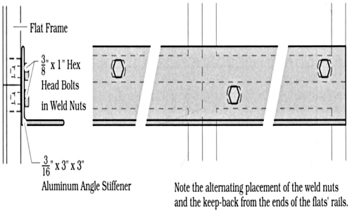
angle-iron stiffener shown in Figure 2 makes a somewhat stronger whaler because the angle iron is less likely to buckle than bar stock. Some shops prefer to use ![]() aluminum angle as illustrated in Figure 3. It goes together faster since there are no tabs at all. The wall flats are laid out face down and pre-cut stiffeners are set in place. Then, holes for weld nuts are drilled through the whalers and the flats’ framing. The whalers are set aside, the weld nuts are welded to the frames, and the flats are picked up for installation at load-in.
aluminum angle as illustrated in Figure 3. It goes together faster since there are no tabs at all. The wall flats are laid out face down and pre-cut stiffeners are set in place. Then, holes for weld nuts are drilled through the whalers and the flats’ framing. The whalers are set aside, the weld nuts are welded to the frames, and the flats are picked up for installation at load-in.


FIGURE 3: ALUMINUM WHALER
