Public Key Infrastructure
Terence Spies, Voltage Security, Inc.
The ability to create, manipulate, and share digital documents has created a host of new applications (email, word processing, ecommerce Web sites), but it also created a new set of problems—namely how to protect the privacy and integrity of digital documents when they’re stored and transmitted. The invention of public key cryptography in the 1970s1—most important, the ability to encrypt data without a shared key and the ability to “sign” data, ensuring its origin and integrity—pointed the way to a solution to those problems. Though these operations are quite conceptually simple, they both rely on the ability to bind a public key (which is typically a large mathematical object) reliably with an identity sensible to the application using the operation (for example, a globally unique name, a legal identifier, or an email address). Public Key Infrastructure (PKI) is the umbrella term used to refer to the protocols and machinery used to perform this binding.
This chapter explains the cryptographic background that forms the foundation of PKI systems, the mechanics of the X.509 PKI system (as elaborated by the Internet Engineering Task Force, or IETF), the practical issues surrounding the implementation of PKI systems, a number of alternative PKI standards, and alternative cryptographic strategies for solving the problem of secure public key distribution. PKI systems are complex objects that have proven difficult to implement properly.2 This chapter aims to survey the basic architecture of PKI systems and some of the mechanisms used to implement them. It does not aim to be a comprehensive guide to all PKI standards or to contain sufficient technical detail to allow implementation of a PKI system. These systems are continually evolving, and the reader interested in building or operating a PKI is advised to consult the current work of standards bodies referenced in this chapter.
1. Cryptographic Background
To understand how PKI systems function, it is necessary to grasp the basics of public key cryptography. PKI systems enable the use of public key cryptography, and they also use public key cryptography as the basis for their operation. There are thousands of varieties of cryptographic algorithms, but we can understand PKI operations by looking at only two: signatures and encryption.
Digital Signatures
The most important cryptographic operation in PKI systems is the digital signature. If two parties are exchanging some digital document, it may be important to protect that data so that the recipient knows that the document has not been altered since it was sent and that any document received was indeed created by the sender. Digital signatures provide these guarantees by creating a data item, typically attached to the document in question that is uniquely tied to the data and the sender. The recipient then has some verification operation that confirms that the signature data matches the sender and the document.
Figure 26.1 illustrates the basic security problem that motivates signatures. An attacker controlling communications between the sender and receiver can insert a bogus document, fooling the receiver.

Figure 26.1 Block diagram of altering an unsigned document.
The aim of the digital signature is to block this attack by attaching a signature that can only be created by the sender, as shown in Figure 26.2.
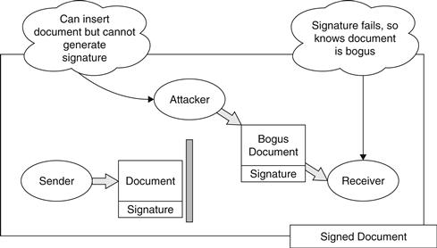
Figure 26.2 Block diagram showing prevention of an alteration attack via digital signature.
Cryptographic algorithms can be used to construct secure digital signatures. These techniques (for example, the RSA or DSA algorithms) all have the same three basic operations, as shown in Table 26.1.
Table 26.1
The Three Fundamental Digital Signature Operations
| Key Generation | Using some random source, the sender creates a public and private key, called Kpublic and Kprivate. Using Kpublic, it is cryptographically difficult to derive Kprivate. The sender then distributes Kpublic, and keeps Kprivate hidden. |
| Signing | Using a document and Kprivate, the sender generates the signature data. |
| Verification | Using the document, the signature, and Kpublic, the receiver (or any other entity with these elements) can test that the signature matches the document, and could only be produced with the Kprivate matching Kpublic. |
Public Key Encryption
Variants of the three operations used to construct digital signatures can also be used to encrypt data. Encryption uses a public key to scramble data in such a way that only the holder of the corresponding private key can unscramble it (see Figure 26.3).
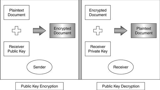
Figure 26.3 The public key encryption and decryption process.
Public key encryption is accomplished with variants of the same three operations used to sign data, as shown in Table 26.2.
Table 26.2
The three fundamental public key encryption operations
| Key Generation | Using some random source, the sender creates a public and private key, called Kpublic and Kprivate. Using Kpublic, it is cryptographically difficult to derive Kprivate. The sender then distributes Kpublic, and keeps Kprivate hidden. |
| Encryption | Using a document and Kpublic, the sender encrypts the document. |
| Decryption | The receiver uses Kprivate to decrypt the document. |
The security of signature and encryption operations depends on two factors: first, the ability to keep the private key private and, second, the ability to reliably tie a public key to a sender. If a private key is known to an attacker, they can then perform the signing operation on arbitrary bogus documents and can also decrypt any document encrypted with the matching public key. The same attacks can be performed if an attacker can convince a sender or receiver to use a bogus public key.
PKI systems are built to securely distribute public keys, thereby preventing attackers from inserting bogus public keys. They do not directly address the security of private keys, which are typically defended by measures at a particular endpoint, such as keeping the private key on a smartcard, encrypting private key data using operating system facilities, or other similar mechanisms. The remainder of this section details the design, implementation, and operation of public key distribution systems.
2. Overview of PKI
PKI systems solve the problem of associating meaningful names with essentially meaningless cryptographic keys. For example, when encrypting an email, a user will typically specify a set of recipients that should be able to decrypt that mail. The user will want to specify these as some kind of name (email address or a name from a directory), not as a set of public keys. In the same way, when signed data is received and verified, the user will want to know what user signed the data, not what public key correctly verified the signature. The design goal of PKI systems is to securely and efficiently connect user identities to the public keys used to encrypt and verify data.
The original Diffie-Hellman paper3 that outlined public key cryptography proposed that this binding would be done through storing public keys in a trusted directory. Whenever a user wanted to encrypt data to another user, they would consult the “public file” and request the public key corresponding to some user. The same operation would yield the public key needed to verify the signature on signed data. The disadvantage of this approach is that the directory must be online and available for every new encryption and verification operation. (Though this older approach was never widely implemented, variants of this approach are now reappearing in newer PKI designs. For more information, see the section on alternative PKI architectures.)
PKI systems solve this online problem and accomplish identity binding by distributing “digital certificates,” chunks of data that contain an identity and a key, all authenticated by digital signature, and providing a mechanism to validate these certificates. Certificates, invented by Kohnfelder in 1978,4 are essentially a digitally signed message from some authority stating “Entity X is associated with public key Y.” Communicating parties can then rely on this statement (to the extent that they trust the authority signing the certificate) to use the public key Y to validate a signature from X or to send an encrypted message to X. Since time may pass between when the signed certificate is produced and when someone uses that certificate, it may be useful to have a validation mechanism to check that the authority still stands by the certificate. We will describe PKI systems in terms of producing and validating certificates.
There are multiple standards that describe the way certificates are formatted. The X.509 standard, promulgated by the ITU,5 is the most widely used and is the certificate format used in the TLS/SSL protocols for secure Internet connections and the S/MIME standards for secured email. The X.509 certificate format also implies a particular model of how certification works. Other standards have attempted to define alternate models of operation and associated certificate models. Among the other standards that describe certificates are Pretty Good Privacy (PGP) and the Simple Public Key Infrastructure (SPKI). In this section, we’ll describe the X.509 PKI model, then describe how these other standards attempt to remediate problems with X.509.
3. The X.509 Model
The X.509 model is the most prevalent standard for certificate-based PKIs, though the standard has evolved such that PKI-using applications on the Internet are mostly based on the set of IETF standards that have evolved and extended the ideas in X.509. X.509-style certificates are the basis for SSL, TLS, many VPNs, the U.S. federal government PKI, and many other widely deployed systems.
The History of X.509
A quick historical preface here is useful to explain some of the properties of X.509. X.509 is part of the X.500 directory standard owned by the International Telecommunications Union Telecommunications Standardization Sector (ITU-T). X.500 specifies a hierarchical directory useful for the X.400 set of messaging standards. As such, it includes a naming system (called distinguished naming) that describes entities by their position in some hierarchy. A sample X.500/X.400 name might look like this:
![]()
This name describes a person with a common name (CN) of Joe Davis who works in an organizational unit (OU) called Human Resources, in an organization called WidgetCo in the United States. These name components were intended to be run by their own directory components (so, for example, there would be Country directories that would point to Organizational directories, etc.), and this hierarchical description was ultimately reflected in the design of the X.509 system. Many of the changes made by IETF and other bodies that have evolved the X509 standard were made to reconcile this hierarchical naming system with the more distributed nature of the Internet.
The X.509 Certificate Model
The X.509 model specifies a system of certifying authorities (CAs) that issue certificates for end entities (users, Web sites, or other entities that hold private keys). A CA-issued certificate will contain (among other data) the name of the end entity, the name of the CA, the end entity’s public key, a validity period, and a certificate serial number. All this information is signed with the CA’s private key. (Additional details on the information in a certificate and how it is encoded appear in the section on the X.509 Certificate Format.) To validate a certificate, a relying party uses the CA’s public key to verify the signature on the certificate, checks that the time falls within the validity period, and may also perform some other online checks.
This process leaves out one important detail: Where did the CA’s public key come from? The answer is that another certificate is typically used to certify the public key of the CA. This “chaining” action of validating a certificate by using the public key from another certificate can be performed any number of times, allowing for arbitrarily deep hierarchies of CAs. Of course, this must terminate at some point, typically at a self-signed certificate that is trusted by the relying party. Trusted self-signed certificates are typically referred to as “root” certificates. Once the relying party has verified the chain of signatures from the end-entity certificate to a trusted root certificate, it can conclude that the end-entity certificate is properly signed and then move onto whatever other validation steps (proper key usage fields, validity dates in some time window, etc.) are required to fully trust the certificate. Figure 26.4 shows the structure of a typical certificate chain.

Figure 26.4 An example X.509 certificate chain.
One other element is required for this system to function securely: CAs must be able to “undo” a certification action. Though a certificate binds an identity to a key, there are many events that may cause that binding to become invalid. For example, a CA operated by a bank may issue a certificate to a newly hired employee that gives that user the ability to sign messages as an employee of the bank. If that person leaves the bank before the certificate expires, the bank needs some way of undoing that certification. The physical compromise of a private key is another circumstance that may require invalidating a certificate. This is accomplished by a validation protocol, where (in the abstract) a user examining a certificate can ask the CA if a certificate is still valid. In practice, revocation protocols are used that simulate this action without actually contacting the CA.
Root certificates are critical to the process of validating public keys through certificates. They must be inherently trusted by the application, since no other certificate signs these certificates. This is most commonly done by installing the certificates as part of the application that will use the certificates under a set of root certificates. For example, Internet Explorer uses X.509 certificates to validate keys used to make Secure Socket Layer (SSL) connections. Internet Explorer has installed a large set of root certificates that can be examined by opening the Internet Options menu item and selecting Certificates in the Content tab of the Options dialog box. A list like the one shown in Figure 26.5 will appear.

Figure 26.5 The Microsoft Internet Explorer trusted root certificates.
This dialog box can also be used to inspect these root certificates. The Microsoft Root certificate details look like the ones shown in Figure 26.6.
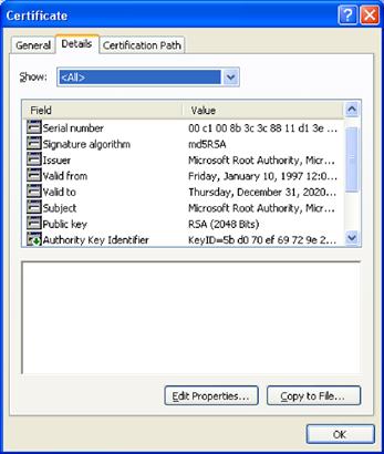
Figure 26.6 A view of the fields in an X.509 certificate using Microsoft Internet Explorer.
The meaning of these fields is explored in subsequent parts of this chapter.
4. X.509 Implementation Architectures
In theory, the Certification Authority is the entity that creates and validates certificates, but in practice, it may be desirable or necessary to delegate the actions of user authentication and certificate validation to other servers. The security of the CA’s signing key is crucial to the security of a PKI system. If we limit the functions of the server that holds that key, it should be subject to less risk of disclosure or illegitimate use. The X.509 architecture defines a delegated server role, the Registration Authority (RA), which allows delegation of authentication. Subsequent extensions to the core X.509 architecture have created a second delegated role, the Validation Authority (VA), which answers queries about the validity of a certificate after creation.
A Registration Authority is typically used to distribute the authentication function needed to issue a certificate without needing to distribute the CA key. The RA’s function is to perform the authentication needed to issue a certificate, then send a signed statement containing the fact that it performed the authentication, the identity to be certified, and the key to be certified. The CA validates the RA’s message and issues a certificate in response.
For example, a large multinational corporation wants to deploy a PKI system using a centralized CA. It wants to issue certificates on the basis of in-person authentication, so it needs some way to distribute authentication to multiple locations in different countries. Copying and distributing the CA signing key creates a number of risks, not only due to the fact that the CA key will be present on multiple servers but also due to the complexities of creating and managing these copies. Sub-CAs could be created for each location, but this requires careful attention to controlling the identities allowed to be certified by each Sub-CA (otherwise, an attacker compromising one Sub-CA could issue a certificate for any identity he liked). One possible way to solve this problem is to create RAs at each location and have the CA check that the RA is authorized to authenticate a particular employee when a certificate is requested. If an attacker subverts a given RA signing key, he can request certificates for employees in the purview of that RA, but it is straightforward, once discovered, to deauthorize the RA, solve the security problem, and create a new RA key.
Validation Authorities are given the ability to revoke certificates (the specific methods used to effect revocation are detailed in the “X.509 Revocation Protocols” section) and offload that function from the CA.
Through judicious use of RAs and VAs, it is possible to construct certification architectures whereby the critical CA server is only accessible to a very small number of other servers, and network security controls can be used to reduce or eliminate threats from outside network entities.
5. X.509 Certificate Validation
X.509 certificate validation is a complex process and can be done to several levels of confidence. This section outlines a typical set of steps involved in validating a certificate, but it is not an exhaustive catalog of the possible methods that can be used. Various applications will often require different validation techniques, depending on the application’s security policy. It is rare for an application to implement certificate validation, since there are several APIs and libraries available to perform this task. Microsoft CryptoAPI, OpenSSL, and the Java JCE all provide certificate validation interfaces. The Server-based Certificate Validity Protocol (SCVP) can also be used to validate a certificate. However, all these interfaces offer a variety of options, and understanding the validation process is essential to properly using these interfaces.
A complete specification of the certificate validation process would require hundreds of pages, so here we supply just a sketch of what happens during certificate validation. It is not a complete description and is purposely simplified. The certificate validation process typically proceeds in three steps and typically takes three inputs. The first is the certificate to be validated, the second is any intermediate certificates acquired by the applications, and the third is a store containing the root and intermediate certificates trusted by the application. The following steps are a simplified outline of how certificates are typically validated. In practice, the introduction of bridge CAs and other nonhierarchical certification models have led to more complex validation procedures. IETF RFC 32806 presents a complete specification for certificate validation, and RFC 41587 presents a specification for constructing a certification path in environments where nonhierarchical certification structures are used.
Validation Step 1: Construct the Chain and Validate Signatures
The contents of the target certificate cannot be trusted until the signature on the certificate is validated, so the first step is to check the signature. To do so, the certificate for the authority that signed the target certificate must be located. This is done by searching the intermediate certificates and certificate store for a certificate with a subject field that matches the issuer field of the target certificate. If multiple certificates match, the validator can search the matching certificates for a Subject Key Identifier extension that matches the Issuer Key Identifier extension in the candidate certificates. If multiple certificates still match, the most recently issued candidate certificate can be used. (Note that, because of potentially revoked intermediate certificates, multiple chains may need to be constructed and examined through Steps 2 and 3 to find the actual valid chain.) Once the proper authority certificate is found, the validator checks the signature on the target certificate using the public key in the authority certificate. If the signature check fails, the validation process can be stopped, and the target certificate deemed invalid.
If the signature matches and the authority certificate is a trusted certificate, the constructed chain is then subjected to Steps 2–4. If not, the authority certificate is treated as a target certificate, and Step 1 is called recursively until it returns a chain to a trusted certificate or fails.
Constructing the complete certificate path requires that the validator is in possession of all the certificates in that path. This requires that the validator keep a database of intermediate certificates or that the protocol using the certificate supply the needed intermediates. The Server Certificate Validation Protocol (SCVP) provides a mechanism to request a certificate chain from a server, which can eliminate these requirements. The SCVP protocol is described in more detail in a subsequent section.
Validation Step 2: Check Validity Dates, Policy and Key Usage
Once a chain has been constructed, various fields in the certificate are checked to ensure that the certificate was issued correctly and that it is currently valid. The following checks should be run on the candidate chain:
The certificate chain times are correct. Each certificate in the chain contains a validity period with a not-before and not-after time. For applications outside validating the signature on a document, the current time must fall after the not-before time and before the not-after time. Some applications may require time nesting, meaning that the validity period for a certificate must fall entirely within the validity period of the issuer’s certificate. It is up to the policy of the application whether it treats out-of-date certificates as invalid or treats them as warning cases that can be overridden by the user. Applications may also treat certificates that are not yet valid differently than certificates that have expired.
Applications that are validating the certificate on a stored document may have to treat validity time as the time that the document was signed as opposed to the time that the signature was checked. There are three cases of interest. The first, and easiest, is where the document signature is checked and the certificate chain validating the public key contains certificates that are currently within their validity time interval. In this case, the validity times are all good, and verification can proceed. The second case is where the certificate chain validating the public key is currently invalid because one or more certificates are out of date and the document is believed to be signed at a time when the chain was out of date. In this case, the validity times are all invalid, and the user should be at least warned.
The ambiguous case arises when the certificate chain is currently out of date, but the chain is believed to have been valid with respect to the time when the document was signed. Depending on its policy, the application can treat this case in several different ways. It can assume that the certificate validity times are strict, and fail to validate the document. Alternatively, it can assume that the certificates were good at the time of signing, and validate the document. The application can also take steps to ensure that this case does not occur by using a time-stamping mechanism in conjunction with signing the document or provide some mechanism for resigning documents before certificate chains expire.
Once the certificate chain has been constructed, the verifier must also verify that various X.509 extension fields are valid. Some common extensions that are relevant to the validity of a certificate path are:
• BasicConstraints. This extension is required for CAs and limits the depth of the certificate chain below a specific CA certificate.
• NameConstraints. This extension limits the namespace of identities certified underneath the given CA certificate. This extension can be used to limit a specific CA to issuing certificates for a given domain or X.400 namespace.
• KeyUsage and ExtendedKeyUsage. These extensions limit the purposes for which a certified key can be used. CA certificates must have KeyUsage set to allow certificate signing. Various values of ExtendedKeyUsage may be required for some certification tasks.
Validation Step 3: Consult Revocation Authorities
Once the verifier has concluded that it has a suitably signed certificate chain with valid dates and proper keyUsage extensions, it may want to consult the revocation authorities named in each certificate to check that the certificates are currently valid. Certificates may contain extensions that point to Certificate Revocation List (CRL) storage locations or to Online Certificate Status Protocol (OCSP) responders. These methods allow the verifier to check that a CA has not revoked the certificate in question.
The next section discusses these methods in more detail. Note that each certificate in the chain may need to be checked for revocation status. The following section on certificate revocation details the mechanisms used to revoke certificates.
6. X.509 Certificate Revocation
Since certificates are typically valid for a significant period of time, it is possible that during the validity period of the certificate, a key may be lost or stolen, an identity may change, or some other event may occur that causes a certificate’s identity binding to become invalid or suspect. To deal with these events, it must be possible for a CA to revoke a certificate, typically by some kind of notification that can be consulted by applications examining the validity of a certificate. Two mechanisms are used to perform this task: Certificate Revocation Lists (CRLs) and the Online Certificate Status Protocol (OCSP).
The original X.509 architecture implemented revocation via a CRL, a periodically issued document containing a list of certificate serial numbers that are revoked by that CA. X.509 has defined two basic CRL formats, V1 and V2. When CA certificates are revoked by a higher-level CA, the serial number of the CA certificate is placed on an Authority Revocation List (ARL), which is formatted identically to a CRL. CRLs and ARLs, as defined in X.509 and IETF RFC 3280, are ASN.1 encoded objects that contain the information shown in Table 26.3.
Table 26.3
Data fields in an X.509 CRL
| Version | Specifies the format of the CRL. Current version is 2 |
| SignatureAlgorithm | Specifies the algorithm used to sign the CRL |
| Issuer | Name of the CA issuing the CRL |
| thisUpdate | Time from when this CRL is valid |
| nextUpdate | Time when the next CRL will be issued |
This header is followed by a sequence of revoked certificate records. Each record contains the information shown in Table 26.4.
Table 26.4
Format of a revocation record in an X.509 CRL
| Serial Number | Serial number of a revoked certificate |
| Revocation Date | Date the revocation is effective |
| CRL Extensions | [Optional] specifies why the certificate is revoked |
The list of revoked certificates is optionally followed by a set of CRL extensions that supply additional information about the CRL and how it should be processed. To process a CRL, the verifying party checks that the CRL has been signed with the key of the named issuer and that the current date is between the thisUpdate time and the nextUpdate time. This time check is crucial because if it is not performed, an attacker could use a revoked certificate by supplying an old CRL where the certificate had not yet appeared. Note that expired certificates are typically removed from the CRL, which prevents the CRL from growing unboundedly over time.
Note that CRLs can only revoke certificates on time boundaries determined by the nextUpdate time. If a CA publishes a CRL every Monday, for example, a certificate that is compromised on a Wednesday will continue to validate until its serial number is published in the CRL on the following Monday. Clients validating certificates may have downloaded the CA’s CRL on Monday and are free to cache the CRL until the nextUpdate time occurs. This caching is important because it means that the CRL is only downloaded once per client per publication period rather than for every certificate validation. However, it has the unavoidable consequence of having a potential time lag between a certificate becoming invalid and its appearance on a CRL. The online certificate validation protocols detailed in the next section attempt to solve this problem.
The costs of maintaining and transmitting CRLs to verifying parties has been repeatedly identified as an important component of the cost of running a PKI system,8,9 and several alternative revocation schemes have been proposed to lower this cost. The cost of CRL distribution was also a factor in the emergence of online certificate status-checking protocols such as OCSP and SCVP.
Delta CRLs
In large systems that issue many certificates, CRLs can potentially become quite lengthy. One approach to reducing the network overhead associated with sending the complete CRL to every verifier is to issue a Delta CRL along with a Base CRL. The Base CRL contains the complete set of revoked certificates up to some point in time, and the accompanying Delta CRL contains only the additional certificates added over some time period. Clients that are capable of processing the Delta CRL can then download the Base CRL less frequently and download the smaller Delta CRL to get recently revoked certificates. Delta CRLs are formatted identically to CRLs but have a critical extension added in the CRL that denotes that they are a Delta, not a Base, CRL. IETF RFC 328010 details the way Delta CRLs are formatted and the set of certificate extensions that indicate that a CA issues Delta CRLs.
Online Certificate Status Protocol
The Online Certificate Status Protocol (OCSP) was designed with the goal of reducing the costs of CRL transmission and eliminating the time lag between certificate invalidity and certificate revocation inherent in CRL-based designs. The idea behind OCSP is straightforward. A CA certificate contains a reference to an OCSP server. A client validating a certificate transmits the certificate serial number, a hash of the issuer name, and a hash of the subject name, to that OCSP server. The OCSP server checks the certificate status and returns an indication as to the current status of the certificate. This removes the need to download the entire list of revoked certificates and allows for essentially instantaneous revocation of invalid certificates. It has the design tradeoff of requiring that clients validating certificates have network connectivity to the required OCSP server.
OCSP responses contain the basic information as to the status of the certificate, in the set of “good,” “revoked,” or “unknown.” They also contain a thisUpdate time, similarly to a CRL, and are signed. Responses can also contain a nextUpdate time, which indicates how long the client can consider the OCSP response definitive. The reason the certificate was revoked can also be returned in the response. OCSP is defined in IETF RFC 2560.11
7. Server-based Certificate Validity Protocol
The X.509 certificate path construction and validation process requires a nontrivial amount of code, the ability to fetch and cache CRLs, and, in the case of mesh and bridge CAs, the ability to interpret CA policies. The Server-based Certificate Validity Protocol12 was designed to reduce the cost of using X.509 certificates by allowing applications to delegate the task of certificate validation to an external server. SCVP offers two levels of functionality: Delegated Path Discovery (DPD), which attempts to locate and construct a complete certificate chain for a given certificate, and Delegated Path Validation (DPV), which performs a complete path validation, including revocation checking, on a certificate chain. The main reason for this division of functionality is that a client can use an untrusted SCVP server for DPD operations, since it will validate the resulting path itself. Only trusted SCVP servers can be used for DPV, since the client must trust the server’s assessment of a certificate’s validity.
SCVP also allows certificate checking according to some defined certification policy. It can be used to centralize policy management for an organization that wants all clients to follow some set of rules with respect to what sets of CAs or certification policies are trusted and so on. To use SCVP, the client sends a query to an SCVP server that contains the following parameters:
• QueriedCerts. This is the set of certificates for which the client wants the server to construct (and optionally validate) paths.
• Checks. The Checks parameter specifies what the client wants the server to do. This parameter can be used to specify that the server should build a path, should build a path and validate it without checking revocation, or should build and fully validate the path.
• WantBack. The WantBack parameter specifies what the server should return from the request. This can range from the public key from the validated certificate path (in which case the client is fully delegating certificate validation to the server) to all certificate chains that the server can locate.
• ValidationPolicy. The ValidationPolicy parameter instructs the server how to validate the resultant certification chain. This parameter can be as simple as “Use the default RFC 3280 validation algorithm” or can specify a wide range of conditions that must be satisfied. Some of the conditions that can be specified with this parameter are:
– KeyUsage and Extended Key Usage. The client can specify a set of KeyUsage or ExtendedKeyUsage fields that must be present in the end-entity certificate. This allows the client to only accept, for example, certificates that are allowed to perform digital signatures.
– UserPolicySet. The client can specify a set of certification policy OIDs that must be present in the CAs used to construct the chain. CAs can assert that they follow some formally defined policy when issuing certificates, and this parameter allows the client to only accept certificates issued under some set of these policies. For example, if a client wanted to only accept certificates acceptable under the Medium Assurance Federal Bridge CA policies, it could assert that policy identifier in this parameter. For more information on policy identifiers, see the section on X.509 extensions.
– InhibitPolicyMapping. When issuing bridge or cross-certificates, a CA can assert that a certificate policy identifier in one domain is equivalent to some other policy identifier within its domain. Using this parameter, the client can state that it does not want to allow these policy equivalences to be used in validating certificates against values in the UserPolicySet parameter.
– TrustAnchors. The client can use this parameter to specify some set of certificates that must be at the top of any acceptable certificate chain. By using this parameter a client could, for example, say that only VeriSign Class 3 certificates were acceptable in this context.
– ResponseFlags. This specifies various options as to how the server should respond (if it needs to sign or otherwise protect the response) and if a cached response is acceptable to the client.
– ValidationTime. The client may want a validation performed as though it was a specific time so that it can find out whether a certificate was valid at some point in the past. Note that SCVP does not allow for “speculative” validation in terms of asking whether a certificate will be valid in the future. This parameter allows the client to specify the validation time to be used by the server.
– IntermediateCerts. The client can use this parameter to give additional certificates that can potentially be used to construct the certificate chain. The server is not obligated to use these certificates. This parameter is used where the client may have received a set of intermediate certificates from a communicating party and is not certain that the SCVP server has possession of these certificates.
– RevInfos. Like the IntermediateCerts parameter, the RevInfos parameter supplies extra information that may be needed to construct or validate the path. Instead of certificates, the RevInfos parameter supplies revocation information such as OCSP responses, CRLs, or Delta CRLs.
8. X.509 Bridge Certification Systems
In practice, large-scale PKI systems proved to be more complex than could be easily handled under the X.509 hierarchical model. For example, Polk and Hastings13 identified a number of policy complexities that presented difficulties when attempting to build a PKI system for the U.S. federal government. In this case, certainly one of the largest PKI projects ever undertaken, they found that the traditional model of a hierarchical certification system was simply unworkable. They state:
The initial designs for a federal PKI were hierarchical in nature because of government’s inherent hierarchical organizational structure. However, these initial PKI plans ran into several obstacles. There was no clear organization within the government that could be identified and agreed upon to run a governmental “root” CA. While the search for an appropriate organization dragged on, federal agencies began to deploy autonomous PKIs to enable their electronic processes. The search for a “root” CA for a hierarchical federal PKI was abandoned, due to the difficulties of imposing a hierarchy after the fact.
Their proposed solution to this problem was to use a “mesh CA” system to establish a Federal Bridge Certification Authority. This Bridge architecture has since been adopted in large PKI systems in Europe and the financial services community in the United States. The details of the European Bridge CA can be found at www.bridge-ca.org. This part of the chapter details the technical design of bridge CAs and the various X.509 certificate features that enable bridges.
Mesh PKIs and Bridge CAs
Bridge CA architectures are implemented using a nonhierarchical certification structure called a Mesh PKI. The classic X.509 architecture joins together multiple PKI systems by subordinating them under a higher-level CA. All certificates chain up to this CA, and that CA essentially creates trust between the CAs below it. Mesh PKIs join together multiple PKI systems using a process called cross-certification that does not create this type of hierarchy. To cross-certify, the top-level CA in a given hierarchy creates a certificate for an external CA, called the bridge CA. This bridge CA then becomes, in a manner of speaking, a Sub-CA under the organization’s CA. However, the bridge CA also creates a certificate for the organizational CA, so it can also be viewed as a top-level CA certifying that organizational CA.
The end result of this cross-certification process is that if two organizations, A and B, have joined the same bridge CA, they can both create certificate chains from their respective trusted CAs through the other organization’s CA to the end-entity certificates that it has created. These chains will be longer than traditional hierarchical chains but will have the same basic verifiable properties. Figure 26.7 shows how two organizations might be connected through a bridge CA and what the resultant certificate chains look like.
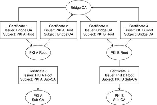
Figure 26.7 Showing the structure of two PKIs connected via a bridge CA.
In the case illustrated in the diagram, a user that trusts certificates issued by PKI A (that is, PKI A Root is a “trust anchor”) can construct a chain to certificates issued by the PKI B Sub-CA, since it can verify Certificate 2 via its trust of the PKI A Root. Certificate 2 then chains to Certificate 3, which chains to Certificate 6. Certificate 6 is then a trusted issuer certificate for certificates issued by the PKI B Sub-CA.
Mesh architectures create two significant technical problems: path construction and policy evaluation. In a hierarchical PKI system, there is only one path from the root certificate to an end-entity certificate. Creating a certificate chain is as simple as taking the current certificate, locating the issuer in the subject field of another certificate, and repeating until the root is reached (completing the chain) or no certificate can be found (failing to construct the chain). In a mesh system, there can now be cyclical loops in which this process can fail to terminate with a failure or success. This is not a difficult problem to solve, but it is more complex to deal with than the hierarchical case.
Policy evaluation becomes much more complex in the mesh case. In the hierarchical CA case, the top-level CA can establish policies that are followed by Sub-CAs, and these policies can be encoded into certificates in an unambiguous way. When multiple PKIs are joined by a bridge CA, these PKIs may have similar policies but can be expressed with different names. PKI A and PKI B may both certify “medium assurance” CAs that perform a certain level of authentication before issuing certificates, but they may have different identifiers for these policies. When joined by a bridge CA, clients may reasonably want to validate certificates issued by both CAs and understand the policies under which those certificates are issued. The PolicyMapping technique allows similar policies under different names from disjoint PKIs to be translated at the bridge CA.
Though none of these problems are insurmountable, they increase the complexity of certificate validation code and helped drive the invention of server-based validation protocols such as SCVP. These protocols delegate path discovery and validation to an external server rather than require that applications integrate this functionality. Though this may lower application complexity, the main benefit of this strategy is that questions of acceptable policies and translation can be configured at one central verification server rather than distributed to every application doing certificate validation.
9. X.509 Certificate Format
The X.509 standard (and the related IETF RFCs) specify a set of data fields that must be present in a properly formatted certificate, a set of optional extension data fields that can be used to supply additional certificate information, how these fields must be signed, and how the signature data is encoded. All these data fields (mandatory fields, optional fields, and the signature) are specified in Abstract Syntax Notation (aka ASN.1), a formal language that allows for exact definitions of the content of data fields and how those fields are arranged in a data structure. An associated specification, Determined Encoding Rules (DER), is used with specific certificate data and the ASN.1 certificate format to create the actual binary certificate data. The ASN.1 standard is authoritatively defined in ITU Recommendation X.693. (For an introduction to ASN.1 and DER, see Kaliski, November 1993.14)
X.509 V1 and V2 Format
The first X.509 certificate standard was published in 1988 as part of the broader X.500 directory standard. X.509 was intended to provide public key-based access control to an X.500 directory and defined a certificate format for that use. This format, now referred to as X.509 v1, defined a static format containing an X.400 issuer name (the name of the CA), an X.400 subject name, a validity period, the key to be certified, and the signature of the CA. Though this basic format allowed for all the basic PKI operations, the format required that all names be in the X.400 form, and it did not allow for any other information to be added to the certificate. The X.509 v2 format added two more Unique ID fields but did not fix the primary deficiencies of the v1 format. As it became clear that name formats would have to be more flexible and certificates would have to accommodate a wider variety of information, work began on a new certificate format.
X.509 V3 Format
The X.509 certificate specification was revised in 1996 to add an optional extension field that allows encoding a set of optional additional data fields into the certificate (see Table 26.5). Though this change might seem minor, in fact it allowed certificates to carry a wide array of information useful for PKI implementation and for the certificate to contain multiple, non-X.400 identities. These extension fields allow key usage policies, CA policy information, revocation pointers, and other relevant information to live in the certificate. The v3 format is the most widely used X.509 variant and is the basis for the certificate profile in RFC 3280,15 issued by the Internet Engineering Task Force.
Table 26.5
Data fields in an X.509 version 3 certificate
| Version | The version of the standard used to format the certificate |
| Serial Number | A number, unique relative to the issuer, for this certificate |
| Signature Algorithm | The specific algorithm used to sign the certificate |
| Issuer | Name of the authority issuing the certificate |
| Validity | The time interval this certificate is valid for |
| Subject | The identity being certified |
| Subject Public Key | The key being bound to the subject |
| Issuer Unique ID | Obsolete field |
| Subject Unique ID | Obsolete field |
| Extensions | A list of additional certificate attributes |
| Signature | A digital signature by the issuer over the certificate data |
X.509 Certificate Extensions
This section contains a partial catalog of common X.509 v3 extensions. There is no existing canonical directory of v3 extensions, so there are undoubtedly extensions in use outside this list.
The most common extensions are defined in RFC 3280,16 which contains the IETF certificate profile used by S/MIME and many SSL/TLS implementations. These extensions address a number of deficiencies in the base X.509 certificate specification, and, in many cases, are essential for constructing a practical PKI system. In particular, the Certificate Policy, Policy Mapping, and Policy Constraints extensions form the basis for the popular bridge CA architectures.
Authority Key Identifier
The Authority Key Identifier extension identifies which specific private key owned by the certificate issuer was used to sign the certificate. The use of this extension allows a single issuer to use multiple private keys and unambiguously identifies which key was used. This allows issuer keys to be refreshed without changing the issuer name and enables handling of events such as an issuer key being compromised or lost.
Subject Key Identifier
The Subject Key Identifier extension, like the Authority Key Identifier, indicates which subject key is contained in the certificate. This extension provides a way to quickly identify which certificates belong to a specific key owned by a subject. If the certificate is a CA certificate, the Subject Key Identifier can be used to construct chains by connecting a Subject Key Identifier with a matching Authority Key Identifier.
Key Usage
A CA might want to issue a certificate that limits the use of a public key. This could lead to an increase in overall system security by segregating encryption keys from signature keys and even segregating signature keys by utilization. For example, an entity may have a key used for signing documents and a key used for decryption of documents. The signing key may be protected by a smart card mechanism that requires a PIN per signing, whereas the encryption key is always available when the user is logged in. The use of this extension allows the CA to express that the encryption key cannot be used to generate signatures and notifies communicating users that they should not encrypt data with the signing public key.
The usage capabilities are defined in a bit field, which allows a single key to have any combination of the defined capabilities. The extension defines the following capabilities:
• digitalSignature. The key can be used to generate digital signatures.
• nonRepudiation. Signatures generated from this key can be tied back to the signer in such a way that the signer cannot deny generating the signature. This capability is used in electronic transaction scenarios in which it is important that signers cannot disavow a transaction.
• keyEncipherment. The key can be used to wrap a symmetric key that is then used to bulk-encrypt data. This is used in communications protocols and applications such as S/MIME in which an algorithm like AES is used to encrypt data, and the public key in the certificate is used to then encipher that AES key. In practice, almost all encryption applications are structured in this manner, since public keys are generally unsuitable for the encryption of bulk data.
• dataEncipherment. The key can be used to directly encrypt data. Because of algorithmic limitations of public encryption algorithms, the keyEncipherment technique is nearly always used instead of directly encrypting data.
• keyAgreement. The key can be used to create a communication key between two parties. This capability can be used in conjunction with the encipherOnly and decipherOnly capabilities.
• keyCertSign. The key can be used to sign another certificate. This is a crucial key usage capability because it essentially allows creation of subcertificates under this certificate, subject to basicConstraints. All CA certificates must have this usage bit set, and all end-entity certificates must not have it set.
• cRLSign. The key can be used to sign a CRL. CA certificates may have this bit set, or they may delegate CRL creation to a different key, in which case this bit will be cleared.
• encipherOnly. When the key is used for keyAgreement, the resultant key can only be used for encryption.
• decipherOnly. When the key is used for keyAgreement, the resultant key can only be used for decryption.
Subject Alternative Name
This extension allows the certificate to define non-X.400 formatted identities for the subject. It supports a variety of namespaces, including email addresses, DNS names for servers, Electronic Document Interchange (EDI) party names, Uniform Resource Identifiers (URIs), and IP addresses, among others.
Policy Extensions
Three important X.509 certificate extensions (Certificate Policy, Policy Mapping, and Policy Constraints) form a complete system for communicating CA policies for the way that certificates are issued and revoked and CA security is maintained. They are interesting in that they communicate information that is more relevant to business and policy decision-making than the other extensions that are used in the technical processes of certificate chain construction and validation. As an example, a variety of CAs run multiple Sub-CAs that issue certificates according to a variety of issuance policies, ranging from “Low Assurance” to “High Assurance.” The CA will typically formally define in a policy document all of its operating policies, state them in a practice statement, define an ASN.1 Object Identifier (OID) that names this policy, and distribute it to parties that will validate those certificates.
The policy extensions allow a CA to attach a policy OID to its certificate, translate policy OIDs between PKIs, and limit the policies that can be used by Sub-CAs.
Certificate Policy
The Certificate Policy extension, if present in an issuer certificate, expresses the policies that are followed by the CA, both in terms of how identities are validated before certificate issuance as well as how certificates are revoked and the operational practices that are used to ensure integrity of the CA. These policies can be expressed in two ways: as an OID, which is a unique number that refers to one given policy, and as a human-readable Certificate Practice Statement (CPS). One Certificate Policy extension can contain both the computer-sensible OID and a printable CPS. One special OID has been set aside for AnyPolicy, which states that the CA may issue certificates under a free-form policy.
IETF RFC 252717 gives a complete description of what should be present in a CA policy document and CPS. More details on the 2527 guidelines are given in the “PKI Policy Description” section.
Policy Mapping
The Policy Mapping extension contains two policy OIDs, one for the issuer domain, the other for the subject domain. When this extension is present, a validating party can consider the two policies identical, which is to say that the subject OID, when present in the chain below the given certificate, can be considered to be the same as the policy named in the issuer OID. This extension is used to join together two PKI systems with functionally similar policies that have different policy reference OIDs.
Policy Constraints
The Policy Constraints extension enables a CA to disable policy mapping for CAs farther down the chain and to require explicit policies in all the CAs below a given CA.
10. PKI Policy Description
In many application contexts, it is important to understand how and when certifying authorities will issue and revoke certificates. Especially when bridge architectures are used, an administrator may need to evaluate a certifying authority’s policy to determine how and when to trust certificates issued under that authority. For example, the U.S. Federal Bridge CA maintains a detailed specification of its operating procedures and requirements for bridged CAs at the U.S. CIO office Web site (www.cio.gov/fpkipa/documents/FBCA_CP_RFC3647.pdf). Many other commercial CAs, such as VeriSign, maintain similar documents.
To make policy evaluation easier and more uniform, IETF RFC 252718 specifies a standard format for certifying authorities to communicate their policy for issuing and revoking certificates. This specification divides a policy specification document into the following sections:
• Introduction. This section describes the type of certificates that the CA issues, the applications in which those certificates can be used, and the OIDs used to identify CA policies. The Introduction also contains the contact information for the institution operating the CA.
• General Provisions. This section details the legal obligations of the CA, any warranties given as to the reliability of the bindings in the certificate, and details as to the legal operation of the CA, including fees and relationship to any relevant laws.
• Identification and Authentication. This section details how certificate requests are authenticated at the CA or RA and how events like name disputes or revocation requests are handled.
• Operational Requirements. This section details how the CA will react in case of key compromise, how it renews keys, how it publishes CRLs or other revocation information, how it is audited, and what records are kept during CA operation.
• Physical, Procedural, and Personnel Security Controls. This section details how the physical location of the CA is controlled and how employees are vetted.
• Technical Security Controls. This section explains how the CA key is generated and protected though its life cycle. CA key generation is typically done through an audited, recorded key generation ceremony to assure certificate users that the CA key was not copied or otherwise compromised during generation.
• Certificate and CRL Profile. The specific policy OIDs published in certificates generated by the CA are given in this section. The information in this section is sufficient to accomplish the technical evaluation of a certificate chain published by this CA.
• Specification Administration. The last section explains the procedures used to maintain and update the certificate policy statement itself.
These policy statements can be substantial documents. The Federal Bridge CA policy statement is 93 pages long; other certificate authorities have similarly exhaustive documents. The aim of these statements is to provide enough legal backing for certificates produced by these CAs so that they can be used to sign legally binding contracts and automate other legally relevant applications.
11. PKI Standards Organizations
The PKIX Working Group was established in the fall of 1995 with the goal of developing Internet standards to support X.509-based PKIs. These specifications form the basis for numerous other IETF specifications that use certificates to secure various protocols, such as S/MIME (for secure email), TLS (for secured TCP connections), and IPsec (for securing Internet packets.)
IETF PKIX
The PKIX working group has produced a complete set of specifications for an X.509-based PKI system. These specifications span 36 RFCs, and at least eight more RFCs are being considered by the group. In addition to the basic core of X.509 certificate profiles and verification strategies, the PKIX drafts cover the format of certificate request messages, certificates for arbitrary attributes (rather than for public keys), and a host of other certificate techniques.
Other IETF groups have produced a group of specifications that detail the usage of certificates in various protocols and applications. In particular, the S/MIME group, which details a method for encrypting email messages, and the SSL/TLS group, which details TCP/IP connection security, use X.509 certificates.
SDSI/SPKI
The Simple Distributed Security Infrastructure (SDSI) group was chartered in 1996 to design a mechanism for distributing public keys that would correct some of the perceived complexities inherent in X.509. In particular, the SDSI group aimed at building a PKI architecture that would not rely on a hierarchical naming system but would instead work with local names that would not have to be enforced to be globally unique. The eventual SDSI design, produced by Ron Rivest and Butler Lampson,19 has a number of unique features:
• Public key-centric design. The SDSI design uses the public key itself (or a hash of the key) as the primary indentifying name. SDSI signature objects can contain naming statements about the holder of a given key, but the names are not intended to be the “durable” name of a entity.
• Free-form namespaces. SDSI imposes no restrictions on what form names must take and imposes no hierarchy that defines a canonical namespace. Instead, any signer may assert identity information about the holder of a key, but no entity is required to use (or believe) the identity bindings of any other particular signer. This allows each application to create a policy about who can create identities, how those identities are verified, and even what constitutes an identity.
• Support for groups and roles. The design of many security constructions (access control lists, for example) often include the ability to refer to groups or roles instead of the identity of individuals. This allows access control and encryption operations to protect data for groups, which may be more natural in some situations.
The Simple Public Key Infrastructure (SPKI) group was started at nearly the same time, with goals similar to the SDSI effort. In 1997, the two groups were merged and the SDSI/SPKI 2.0 specification was produced, incorporating ideas from both architectures.
IETF OpenPGP
The Pretty Good Privacy (PGP) public key system, created by Philip Zimmermann, is a widely deployed PKI system that allows for the signing and encryption of files and email. Unlike the X.509 PKI architecture, the PGP PKI system uses the notion of a “Web of Trust” to bind identities to keys. The Web of Trust (WoT)20 replaces the X.509 idea of identity binding via an authoritative server, with identity binding via multiple semitrusted paths.
In a WoT system, the end user maintains a database of matching keys and identities, each of which are given two trust ratings. The first trust rating denotes how trusted the binding between the key and the identity is, and the second denotes how trusted a particular identity is to “introduce” new bindings. Users can create and sign a certificate as well as import certificates created by other users. Importing a new certificate is treated as an introduction. When a given identity and key in a database are signed by enough trusted identities, that binding is treated as trusted.
Because PGP identities are not bound by an authoritative server, there is also no authoritative server that can revoke a key. Instead, the PGP model states that the holder of a key can revoke that key by posting a signed revocation message to a public server. Any user seeing a properly signed revocation message then removes that key from her database. Because revocation messages must be signed, only the holder of the key can produce them, so it is impossible to produce a false revocation without compromising the key. If an attacker does compromise the key, then production of a revocation message from that compromised key actually improves the security of the overall system because it warns other users not to trust that key.
12. PGP Certificate Formats
To support the unique features of the Web of Trust system, PGP invented a very flexible packetized message format that can encode encrypted messages, signed messages, key database entries, key revocation messages, and certificates. This packetized design, described in IETF RFC 2440, allows a PGP certificate to contain a variable number of names and signatures, as opposed to the single-certification model used in X.509.
A PGP certificate (known as a transferrable public key) contains three main sections of packetized data. The first section contains the main public key itself, potentially followed by some set of relevant revocation packets. The next section contains a set of User ID packets, which are identities to be bound to the main public key. Each User ID packet is optionally followed by a set of Signature packets, each of which contains an identity and a signature of the User ID packet and the main public key. Each of these Signature packets essentially forms an identity binding. Because each PGP certificate can contain any number of these User ID/Signature elements, a single certificate can assert that a public key is bound to multiple identities (for example, multiple email addresses that correspond to a single user), certified by multiple signers. This multiple-signer approach enables the Web of Trust model. The last section of the certificate is optional and may contain multiple subkeys, which are single-function keys (for example, an encryption-only key) also owned by the holder of the main public key. Each of these subkeys must be signed by the main public key.
PGP Signature packets contain all the information needed to perform a certification, including time intervals for which the signature is valid. Figure 26.8 shows how the multiname, multisignature PGP format differs from the single-name with single-signature X.509 format.
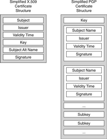
Figure 26.8 Comparing X.509 and PGP certificate structures.
13. PGP PKI Implementations
The PGP PKI system is implemented in commercial products sold by the PGP corporation, and several open-source projects, including Gnu Privacy Guard (GnuPG) and OpenPGP. Thawte offers a Web of Trust service that connects people with “Web of Trust notaries” that can build trusted introductions. PGP Corporation operates a PGP Global Directory that contains PGP keys along with an email confirmation service to make key certification easier.
The OpenPGP group (www.openpgp.org) maintains the IETF specification (RFC 2440) for the PGP message and certificate format.
14. W3C
The World Wide Web Consortium (W3C) standards group has published a series of standards on encrypting and signing XML documents. These standards, XML Signature and XML Encryption, have a companion PKI specification called XKMS (XML Key Management Specification).
The XKMS specification describes a meta-PKI that can be used to register, locate, and validate keys that may be certified by an outside X.509 CA, a PGP referrer, a SPKI key signer, or the XKMS infrastructure itself. The specification contains two protocol specifications, X-KISS (XML Key Information Service Specification) and X-KRSS (XML Key Registration Service Specification). X-KISS is used to find and validate a public key referenced in an XML document, and X-KRSS is used to register a public key so that it can be located by X-KISS requests.
15. Alternative PKI architectures
PKI systems have proven remarkably effective tools for some protocols, most notably SSL, which has emerged as the dominant standard for encrypting Internet traffic. Deploying PKI systems for other types of applications or as a general key management system has not been as successful. The differentiating factor seems to be that PKI keys for machine end-entities (such as Web sites) do not encounter usability hurdles that emerge when issuing PKI keys for human end-entities. Peter Gutmann21 has a number of overviews of PKI that present the fundamental difficulties of classic X.509 PKI architectures. Alma Whitten and Doug Tygar22 published “Why Johnny Can’t Encrypt,” a study of various users attempting to encrypt email messages using certificates. This study showed substantial user failure rates due to the complexities of understanding certificate naming and validation practices. A subsequent study23 showed similar results when using X.509 certificates with S/MIME encryption in Microsoft Outlook Express.
16. Modified X.509 Architectures
Some researchers have proposed modifications or redesigns of the X.509 architecture to make obtaining a certificate easier and to lower the cost of operating applications that depend on certificates. The goal of these systems is often to allow Internet-based services to use certificate-based signature and encryption services without requiring the user to consciously interact with certification services or even understand that certificates are being utilized.
Perlman and Kaufman’s User-Centric PKI
Perlman and Kaufman proposed the User-Centric PKI,24 which allows the user to act as his own CA, with authentication provided through individual registration with service providers. This method has several features that attempt to protect user privacy through allowing the user to pick the attributes that are visible to a specific service provider.
Gutmann’s Plug and Play PKI
Peter Gutmann’s proposed “Plug and Play PKI”25 provides for similar self-registration with a service provider and adds location protocols to establish ways to contact certifying services. The goal is to build a PKI that provides a reasonable level of security and that is essentially transparent to the end user.
Callas’s Self-Assembling PKI
In 2003, Jon Callas26 proposed a PKI system that would use existing standard PKI elements bound together by a “robot” server that would examine messages sent between users and attempt to find certificates that could be used to secure the message. In the absence of an available certificate, the robot would create a key on behalf of the user and send a message requesting authentication. This system has the benefit of speeding deployment of PKI systems for email authentication, but it loses many of the strict authentication attributes that drove the development of the X.509 and IETF PKI standards.
17. Alternative Key Management Models
PKI systems can be used for encryption as well as digital signatures, but these two applications have different operational characteristics. In particular, systems that use PKIs for encryption require that an encrypting party has the ability to locate certificates for its desired set of recipients. In digital signature applications, a signer only requires access to his own private key and certificate. The certificates required to verify the signature can be sent with the signed document, so there is no requirement for verifiers to locate arbitrary certificates. These difficulties have been identified as factors contributing to the difficulty of practical deployment of PKI-based encryption systems such as S/MIME.
In 1984, Adi Shamir27 proposed an Identity-Based Encryption (IBE) system for email encryption. In the identity-based model, any string can be mathematically transformed into a public key, typically using some public information from a server. A message can then be encrypted with this key. To decrypt, the message recipient contacts the server and requests a corresponding private key. The server is able to mathematically derive a private key, which is returned to the recipient. Shamir disclosed how to perform a signature operation in this model but did not give a solution for encryption.
This approach has significant advantages over the traditional PKI model of encryption. The most obvious is the ability to send an encrypted message without locating a certificate for a given recipient. There are other points of differentiation:
• Key recovery. In the traditional PKI model, if a recipient loses the private key corresponding to a certificate, all messages encrypted to that certificate’s public key cannot be decrypted. In the IBE model, the server can recompute lost private keys. If messages must be recoverable for legal or other business reasons, PKI systems typically add mandatory secondary public keys to which senders must encrypt messages to.
• Group support. Since any string can be transformed to a public key, a group name can be supplied instead of an individual identity. In the traditional PKI model, groups are done by either expanding a group to a set of individuals at encrypt time or issuing group certificates. Group certificates pose serious difficulties with revocation, since individuals can only be removed from a group as often as revocation is updated.
In 2001, Boneh and Franklin gave the first fully described secure and efficient method for IBE.28 This was followed by a number of variant techniques, including Hierarchical Identity-Based Encryption (HIBE) and Certificateless Encryption. HIBE allows multiple key servers to be used, each of which control part of the namespace used for encryption. Certificateless29 encryption adds the ability to encrypt to an end user using an identity but in such a way that the key server cannot read messages. IBE systems have been commercialized and are the subject of standards under the IETF (RFC 5091) and IEEE (1363.3).
1W. Diffie and M. E. Hellman, “New directions in cryptography,” IEEE Trans. Inform. Theory, IT-22, 6, 1976, pp. 644–654.
2P. Gutmann, “Plug-and-Play PKI: A PKI Your Mother Can Use,” in Proc. 12th Usenix Security Symp., Usenix Assoc., 2003, pp. 45–58.
3W. Diffie and M. E. Hellman, “New directions in cryptography,” IEEE Trans. Inform. Theory, IT-22, 6, 1976, pp. 644–654.
4Kohnfelder, L., “Towards a practical public-key cryptosystem,” Bachelor’s thesis, Department of Computer Science, Massachusetts Institute of Technology (June 1978).
5ITU-T Recommendation X.509 (1997 E): Information Technology – Open Systems Interconnection – The Directory: Authentication Framework, June 1997.
6R. Housely, W. Ford, W. Polk, and D. Solo, “Internet X.509 public key infrastructure certificate and certificate revocation list profile,” IETF RFC 3280, April 2002.
7M. Cooper, Y. Dzambasow, P. Hesse, S. Joseph, and R. Nicholas, “Internet X.509 public key infrastructure: certification path building,” IETF RFC 4158, September 2005.
8Shimshon Berkovits, Santosh Chokhani, Judith A. Furlong, Jisoo A. Geiter, and Jonathan C. Guild, Public Key Infrastructure Study: Final Report, produced by the MITRE Corporation for NIST, April 1994.
9S. Micali, “Efficient certificate revocation,” technical report TM-542b, MIT Laboratory for Computer Science, March 22, 1996. http://citeseer.ist.psu.edu/micali96efficient.html.
10R. Housely, W. Ford, W. Polk, and D. Solo, “Internet X.509 public key infrastructure certificate and certificate revocation list profile,” IETF RFC 3280, April 2002.
11M. Myers, R. Ankeny, A. Malpani, S. Galperin, and C. Adams, “X.509 Internet public key infrastructure: Online Certificate Status Protocol – OCSP,” IETF RFC 2560, June 1999.
12T. Freeman, R. Housely, A. Malpani, D. Cooper, and W. Polk, “Server-Based Certificate Validation Protocol (SCVP),” IETF RFC 5055, December 2007.
13W.T. Polk and N.E. Hastings, “Bridge certification authorities: connecting B2B public key infrastructures,” white paper, U.S. National Institute of Standards and Technology, 2001, Available at http://csrc.nist.gov/groups/ST/crypto_apps_infra/documents/B2B-article.pdf.
14B.S. Kaliski, Jr., “A layman’s guide to a subset of ASN.1, BER, and DER” An RSA Technical Note, Revised November 1, 1993, available at ftp.rsasecurity.com/pub/pkcs/ascii/layman.asc.
15R. Housely, W. Ford, W. Polk, and D. Solo, “Internet X.509 public key infrastructure certificate and certificate revocation list profile,” IETF RFC 3280, April 2002.
16R. Housely, W. Ford, W. Polk, and D. Solo, “Internet X.509 public key infrastructure certificate and certificate revocation list profile,” IETF RFC 3280, April 2002.
17S. Chokhani and W. Ford, “Internet X.509 public key infrastructure: certificate policy and certification practices framework,” IETF RFC 2527, March 1999.
18S. Chokhani and W. Ford, “Internet X.509 public key infrastructure: certificate policy and certification practices framework,” IETF RFC 2527, March 1999.
19R. Rivest and B. Lampson, “SDSI-A simple distributed security infrastructure,” Oct. 1996.
20Alfarez Abdul-Rahman, “The PGP trust model,” EDI- Forum, April 1997, available at www.cs.ucl.ac.uk/staff/F.AbdulRahman/docs/.
21P. Gutmann, “Plug-and-play PKI: A PKI your mother can use,” in Proc. 12th Usenix Security Symp., Usenix Assoc., 2003, pp. 45–58.
22A. Whitten and J.D. Tygar, “Why Johnny can’t encrypt: a usability evaluation of PGP 5.0,” in Proceedings of the 8th USENIX Security Symposium, August 1999.
23S. Garfinkel and R. Miller, “Johnny 2: A user test of key continuity management with S/MIME and outlook express,” Symposium on Usable Privacy and Security, 2005.
24R. Perlman and C. Kaufman, “User-centric PKI”, 7th symposium on identity and trust on the internet.
25P. Gutmann, “Plug-and-Play PKI: A PKI Your Mother Can Use,” in Proc. 12th Usenix Security Symp., Usenix Assoc., 2003, pp. 45–58.
26J. Callas, “Improving Message Security With a Self-Assembling PKI,” In 2nd Annual PKI Research Workshop Pre-Proceedings, April 2003, http://citeseer.ist.psu.edu/callas03improving.html.
27A. Shamir, “Identity-based Cryptosystems and Signature Schemes,” Advances in Cryptology – Crypto ’84, Lecture Notes in Computer Science, Vol. 196, Springer-Verlag, pp. 47–53, 1984.
28D. Boneh and M. Franklin, “Identity-based encryption from the Weil Pairing,” SIAM J. of Computing, Vol. 32, No. 3, pp. 586–615, 2003.
29S. S. Al-Riyami, K. Paterson, “Certificateless public key cryptography,” In: C. S. Laih (ed.), Advances in Cryptology – Asiacrypt 2003, Lecture Notes in Computer Science, Vol. 2894, pp. 452–473, Springer-Verlag, 2003.