SAN Security
John McGowan, EMC Corporation
Jeffrey Bardin, Independent consultant
John McDonald, EMC Corporation
As with any IT subsystem, implementing the appropriate level of security for storage area networks (SANs) depends on many factors. The resources expended on protecting the SAN should reflect the value of the information stored on the SAN using a risk-based approach. A full assessment and classification of the data including threats, vulnerabilities, existing controls, and potential impact should the loss, disclosure, modification, interruption, and/or destruction of the data occur should be performed prior to configuration of the SAN. Anytime you consider security prior to actual build-out of a system or device, your expenditures are lower than attempting to bolt on the security after the fact. There are a number of inexpensive steps that can be taken to ensure that security is appropriate for the classification of data stored in the SAN.
As the use of SANs increases, the amount of data being stored increases exponentially, making the SAN a target for hackers, criminals, and disgruntled employees. To effectively protect a SAN, it is important to understand what actions increase security and what impact these actions have on the performance and usability of the environment. Ensuring a balance among protection capability, cost, performance, and operational considerations must be at the top of your list when applying controls to your SAN environment.
One thing to consider is that the most probable avenue of attack in a SAN is through the hosts connected to the SAN. There are potentially thousands of host, application, and operating system-specific security considerations that are beyond the scope of this chapter but should be followed as your systems and application administrators properly configure their owned devices.
Information security, that aspect of security that seeks to protect data confidentiality, data integrity, and access to the data, is an established commercial sector with a wide variety of vendors marketing mature products and technologies, such as VPNs, firewalls, antivirus, and content management. Recently there has been a subtle development in security. Organizations are expanding their security perspectives to secure not only end-user data access and the perimeter of the organization but also the data within the datacenter. Several factors drive these recent developments. The continuing expansion of the network and the continued shrinking of the perimeter expose datacenter resources and the storage infrastructure to new vulnerabilities. Data aggregation increases the impact of a security breach. IP-based storage networking potentially exposes storage resources to traditional network vulnerabilities. Recently the delineation between a back-end datacenter and front-end network perimeter is less clear. Storage resources are potentially becoming exposed to unauthorized users inside and outside the enterprise. In addition, as the plethora of compliance regulations continues to expand and become more complicated, IT managers are faced with addressing the threat of security breaches from both within and outside the organization. Complex international regulations require a greater focus on protecting not only the network but the data itself. This chapter describes best practices for enhancing and applying security of SANs.
1. Organizational Structure
Every company has its own organizational structures and security requirements. These are typically driven by the type of business, types of regulations and statutes that focus corporate compliance, and the type of data stored in the SAN. All factors should be evaluated when developing a security policy that is appropriate for your environment. It is wise to incorporate existing security policies such as acceptable use policies (AUPs), data classification, and intellectual property policies along playbooks or standard operating procedures (SOPs) describing how the data is stored and managed.
As with best practice, implementation can lead to tradeoffs. Making a SAN more secure may result in additional management overhead or a reduction in ease-of-use capabilities or the introduction of ease-of-use capabilities that reduce the overall SAN security posture. The use of encryption could create an unacceptable performance hit if not applied properly. You may even find that SAN security best practices conflict with other IT policies. In some instances, functions required to implement a recommendation may not be available on a certain SAN. Other compensating controls need to be considered such as a process, policy, or triggered script that assists in implementing the control. Your implementation of security controls should be based on risk as defined in an assessment process during SAN deployment.
AAA
Authentication, authorization, and accounting (AAA) is a term for a framework for intelligently controlling access to computer resources, enforcing policies, auditing usage, and providing the information necessary to bill for services. These combined processes are important for effective network management and security.
Authentication provides a way of identifying a user, typically by having the user enter a valid username and password before granting access. The process of authentication is based on each user having a unique set of criteria for gaining access. The AAA server compares the user’s credentials with credentials stored in a database. If the credentials match, the user is granted access to the resource.
Authorization is the process of enforcing policies: determining what types or qualities of activities, resources, or services a user is permitted. For example, after logging into a system, the user may try to issue commands. The authorization process determines whether the user has the authority to issue such commands. Once you have authenticated a user, she may be authorized for multiple types of access or activity.
The final process in the AAA framework is accounting, which measures the resources a user consumes during access. This can include the amount of system time or the amount of data a user has sent and/or received during a session. Accounting is accomplished by logging session statistics and usage information and is used for authorization control, billing, trend analysis, resource utilization, and capacity planning activities.
Authentication, authorization, and accounting services are often provided by a dedicated AAA server, a program that performs these functions. A common standard by which network access servers interface with the AAA server is the Remote Authentication Dial-In User Service (RADIUS).
Assessment and Design
The first step in developing adequate datacenter controls is to know what the controls need to address—for example, the vulnerabilities that can be exploited. Some threats may seem very difficult, and hence unlikely to be exploited, but it is an essential piece of the process to understand them so that you can demonstrate that they are either mitigated or that it is not commercially reasonable to fix the problem. This step is essential since it is not usually the vulnerabilities that you already know about that will be exploited. Once you have identified the gaps in the datacenter, you can communicate the vulnerabilities to your data by implementing a comprehensive SAN security program. The first step is to develop a storage security standard that outlines the architecture, workflow process, and technologies to leverage when deploying enterprisewide storage networks. Today SAN security solutions are available to meet some needs of every individual topology, incorporating a wide variety of vendor products and architectural needs. It is essential that corporations aggressively take on the challenge of integrating these new security features and technologies to interoperate with existing security technologies while complying with and redefining existing standards, policies, and processes.
The remainder of this section details the tasks within the planning and design phase. Included in this section are architecture planning and design details, considerations for design, best practices, and notes on data collection and documentation.
Review Topology and Architecture Options
Fabric security augments overall application security. It is not sufficient on its own; host and disk security are also required. You should consider each portion of the customer’s SAN when determining the correct security configuration. Review the current security infrastructure and discuss present and future needs. Listed here are the most common discussion segments:
• SAN management access. Secure access to management services.
• Fabric access. Secure device access to fabric service.
• Target access. Secure access to targets and Logical Unit Numbers (LUNs).
• SAN protocol. Secure switch-to-switch communication protocols.
• IP storage access. Secure Fibre Channel over TCP/IP (FCIP) and Internet Small Computer System Interface (iSCSI) services.
• Data integrity and secrecy. Encryption of data both in transit and at rest.
Additional subjects to include in a networked storage strategy involve:
• Securing storage networking ports and devices
• Securing transmission and ISL interfaces
• Securing management tools and interfaces (Simple Network Management Protocol (SNMP), Telnet, IP interfaces)
• Securing storage resources and volumes
• File system permissions for Network-attached Storage (NAS) file access using Network File System (NFS), and Common Internet File System (CIFS)
• Operating system access control and management interfaces
• Control and monitor root and other supervisory access
• Physical and logical security and protection
• Virus protection and detection on management servers and PC
• Disabling SNMP management interfaces not used or needed
• Restricting use and access to Telnet and FTP for components
There are a several major areas of focus for securing storage networks. These include securing the fabric and its access, securing the data and where it is stored, securing the components, securing the transports, and securing the management tools and interfaces. This part of the chapter describes the following components:
Restricting Access to Storage
Securing a storage network involves making sure that you protect the SAN itself as well as the storage. LUN mapping works by creating an access table on the storage device or host servers (persistent binding) that determines what servers, using World Wide Node Names (WWNN) or World Wide Port Names (WWPN), can access (read, read/write, etc.) a specific volume or LUN. Servers that do not have access to the specific LUN receive an I/O reject error or may not see the storage at all. Storage-based security is the last line of defense when it comes to controlling access to a storage resource LUN.
Device masking hides the existence of a storage device from all but a desired set of host connections. Because Fibre Channel fabrics support zoning based on individual devices (WWN Zoning) it is possible to perform device masking in the fabric (King, 2001).
2. Access Control Lists (ACL) and Policies
Authentication involves verifying the identity of people and devices that are attempting to gain authorization to storage network resources. Authentication involves use of a server such as a remote access dial-up server (RADIUS) commonly used in network environments to verify identity credentials. Access control lists implement authorization to determine who and what can have access to storage network resources. When looking at controlling access and isolating traffic within a single switch or director as well as in a single fabric of two or more switches all connected together, use the following techniques:
• Fabric, switch, and port binding with policies and ACLs
• Fabric and device zoning to control access
• Networking segmentation (traffic isolation)
• Port isolation (port blocks, prohibits, port isolation, and disablement)
• Partitioning and segmentation (logical domains, Virtual Storage Area Network (VSAN), Logical Storage Area Network (LSAN), virtual switches)
Data Integrity Field (DIF)
DIF provides a standard data-checking mechanism to monitor the integrity of data. DIF sends a block of information with integrity checks to an HBA. The HBA validates the data and sends the data block with its integrity check across the Fibre Channel fabric to the storage array. The storage array in turn validates the metadata and writes the data to Redundant Array of Independent Disks (RAID) memory. The array then sends the block of data to the disk, which validates the information before writing it to disk. DIF pinpoints where in the process of writing data to disk that the corruption occurred.
Diffie-Hellman: Challenge Handshake Authentication Protocol (DH-CHAP)
DH-CHAP is a forthcoming Internet Standard for the authentication of devices connecting to a Fibre Channel switch. DH-CHAP is a secure key-exchange authentication protocol that supports both switch-to-switch and host-to-switch authentication. DH-CHAP supports MD-5 and SHA-1 algorithm-based authentication.
Fibre-Channel Security Protocol (FC-SP)
FC-SP is a security framework that includes protocols to enhance Fibre Channel security in several areas, including authentication of Fibre Channel devices, cryptographically secure key exchange, and cryptographically secure communication between Fibre Channel devices. FC-SP is focused on protecting data in transit throughout the Fibre Channel network. FC-SP does not address the security of data which is stored on the Fibre Channel network.
Fibre-Channel Authentication Protocol (FCAP)
FCAP is an optional authentication mechanism employed between any two devices or entities on a Fibre Channel network using certificates or optional keys.
Fibre-Channel Password Authentication Protocol (FCPAP)
FCPAP is an optional password based authentication and key exchange protocol that is utilized in Fibre Channel networks. FCPAP is used to mutually authenticate Fibre Channel ports to each other.
Switch Link Authentication Protocol (SLAP)
SLAP is an authentication method for Fibre Channel switches that utilizes digital certificates to authenticate switch ports. SLAP was designed to prevent the unauthorized addition of switches into a Fibre Channel network.
Port Blocks and Port Prohibits
You can use zoning to isolate ports—for example, Fiber Connectivity (FICON) ports from open systems ports, and traffic. Other capabilities that exist on switches and directors that support Enterprise Systems Connection (ESCON) or FICON are port blocks and port prohibits. Port blocks and port prohibits are another approach independent of the upper-layer fabric and name server for protecting ESCON and FICON ports. Unlike fabric zoning that can span multiple switches and directors in a fabric, port blocks and prohibits are specific to an individual director.
Zoning and Isolating Resources
While a Fibre Channel-based storage network can theoretically have approximately 16 million addresses for servers, devices, and switches, the reality is a bit lower. Zones can be unique with devices isolated from each, or they can overlap with devices existing in different overlapping zones. You can accomplish port and fabric security using zoning combinations, including WWNN Soft zoning, WWPN Soft zoning as part of the T11 FC-SW-2 standard, along with hardware enforced port zoning.
3. Physical Access
Physical access is arguably one of the most critical aspects of Fibre Channel SAN security. The Fibre Channel protocol is not designed to be routed (although SANs can be bridged), which means that what happens in the SAN should stay in the SAN. By implementing the rest of the best practices discussed in this chapter, strong physical access controls can almost ensure that any attempts to access the SAN from the outside will be thwarted, since an attacker would need to physically connect a fiber optic cable to a switch or array to gain access.
Physical controls should also include clear labeling for all cables and components. In performing a physical audit of the infrastructure, clear and accurate labeling will ensure that any changes are immediately detectable.
Controlling physical access to any storage medium is also critical. This applies not only to the disk drives in a SAN storage system but to any copies of the data, such as backup tapes. The best security management system can be easily defeated if an attacker can walk into a lightly controlled office area and walk out with backup tapes that were stored there.
4. Change Management
A documented and enforced process should be in place for any actions that may change the configuration of any component connected to the SAN. Changes should be reviewed beforehand to ensure that they will not compromise security, and any unapproved changes uncovered during a regular audit (discussed shortly) should be thoroughly investigated.
5. Password Policies
Normal password-related best practices, such as regular changing of passwords and the use of hard-to-guess passwords, should be implemented for all components on the SAN. This includes the storage systems, switches and hubs, hosts, and so on.
The generally accepted best practice for the industry is that passwords should be changed every three to six months, and passwords should be a minimum of eight characters long and include at least one number or symbol. However, customers should follow the policies that have been established to address their particular business requirements.
6. Defense in Depth
No single method of protecting a SAN can be considered adequate in the light of constantly evolving threats. The best possible approach is to implement a policy of layers of protection for every aspect of the environment, which forces an attacker to defeat multiple mechanisms to achieve their goal, increasing the probability of an attack being detected and defeated. The LAN that interconnects the SAN component’s management interfaces, which is the most likely avenue of attack, should be protected by multiple layers of security measures, such as firewalls, security monitoring tools, and so forth. The first phase of many attempts to attack the SAN will usually come through these LAN (Ethernet) management connections.
7. Vendor Security Review
In considering new hardware and software that will be installed in or interact with the SAN, a security review should be performed with customer security personnel, customer technical/administrative personnel, and vendor technical personnel to gain a complete understanding of the security capabilities of the product and how they can be integrated into the existing security framework.
Failure to implement any of these basic security practices can increase the possibility that a SAN may come under attack and that any such an attack may succeed in impacting the ability of the SAN to perform its functions. For additional information on IT security best practices, refer to the SANS Institute’s Resources Web site (www.sans.org/resources/) and to the SAN Security site (www.sansecurity.com).
8. Data Classification
To develop and implement security policies and tools that effectively protect the data in a SAN at an appropriate level, it is important to understand the value of the data to the organization. Though implementing a one-size-fits-all approach to protecting all the data can simplify security management, such an approach may impose excessive costs for certain types of data while leaving other data underprotected. For example, encrypting data on the host can provide a significant level of protection; however, such encryption can impose significant overhead on the host processing, reducing performance for the entire environment.
A review of all data on the SAN should be performed and appropriate classifications assigned based on business requirements. These classifications should be assigned appropriate protection requirements.
9. Security Management
When any new SAN component (such as a storage array, switch, or host) is installed, it usually contains at least one factory configured access method (such as a default username/password). It is imperative that any such access method be immediately reconfigured to conform to the security policies that have been set up for the rest of the environment. Strong passwords should be utilized (as discussed shortly) and, if possible, the account name should be changed.
Security Setup
More complex components, such as the hosts and storage systems, provide even more sophisticated security mechanisms, such as support for access domains, which allow them to be integrated into a broader security infrastructure. The mechanism should be configured according to established security policies immediately on installation.
Unused Capabilities
Most SAN hardware provides multiple methods of access and monitoring, such as a Web-based interface, a telnet command-line interface, and an SNMP interface. Many also provide some method for uploading new versions of firmware, such as FTP or Trivial File Transfer Protocol (TFTP). Any interface capabilities that will not be utilized on a regular basis should be explicitly disabled on every SAN device. Update interfaces such as FTP should only be enabled while an update is being performed and should be immediately disabled when done, to prevent them from being exploited during attacks.
On SAN switches any ports that will not be used in the configuration should also be explicitly disabled to prevent them from being utilized if an attacker does manage to gain physical access to the SAN.
10. Auditing
Virtually every component in a SAN provides some form of capability to log changes when they occur. For example, some storage systems make a log entry when a new LUN is created; most Fibre Channel switches make log entries when zoning is changed. Regular audits should be performed to ensure that the current configuration of the SAN and all its components agree with the currently documented configuration, including any changes made through the change management system.
Automated tools and scripts can be used to implement an effective auditing process. Most SAN components provide the capability to download a detailed text listing that shows the current configuration. By performing this task on a regular basis and comparing the results to established baseline configurations, changes can be quickly detected and, if necessary, investigated.
Updates
All patches and software/firmware updates to any SAN components should be reviewed in a timely manner to determine whether they may have an impact on security. If a particular update includes changes to address known security vulnerabilities, it should be applied as quickly as possible.
Monitoring
It is important to continuously monitor an infrastructure to detect and prevent attacks. For example, a brute-force password attack that generates an abnormally high amount of TCP/IP network traffic to a SAN switch can be easily detected and stopped using standard network monitoring tools before any impact occurs.
Monitoring can also detect changes to the SAN configuration that may indicate an attack is underway. For example, if an attacker attempts to “spoof” the world wide name (WWN) of another server to gain access to its storage, most switches will detect the existence of a duplicate WWN and generate error messages.
Security Maintenance
The security configuration of the SAN should be updated in a timely manner to reflect changes in the environment—for example, the removal of a previously authorized user or host from the infrastructure due to termination or transfer. SAN ports should be managed to ensure that any unused ports are explicitly disabled when not being used, such as when a previously connected server is removed from the SAN.
Configuration Information Protection
All attacks on a SAN start with obtaining information on the SAN’s configuration, such as number and types of components, their configuration, and existing accounts. Without sufficient information it is virtually impossible to carry out a successful attack on a SAN environment. It is therefore critical that any information that provides details on how the IT infrastructure (including the SAN) is configured be carefully controlled. Some examples of information that can be used to plan an attack include:
• Network diagrams with TCP/IP addresses of SAN components
• SAN diagrams with component information
All such information should be labeled appropriately and its distribution restricted to only IT personnel with a confirmed need to know. When it is necessary to share this information with outside agencies (such as vendors when creating a Request for Proposal (RFP)). the information should be distributed utilizing positive controls, such as a password-protected view-only Adobe Acrobat PDF document.
11. Management Access: Separation of Functions
Management of functions supported by the SAN should be divided up among personnel to ensure that no single person has control over the entire SAN. For example, one individual should be responsible for managing the storage systems, one responsible for configuring the SAN hardware itself, and a different individual should be responsible for managing the hosts connected to the SAN. When a change needs to be made it should be requested utilizing the change management system (see previous discussion), reviewed by all personnel involved, and thoroughly documented.
Limit Tool Access
Many Fibre Channel Host Bus Adapter (HBA) vendors provide the capability to change the world wide name of an HBA. This is usually accomplished via either a host-based utility or a firmware utility that gets executed when the host is booted. In the case of a host-based utility, such utilities should be removed and the host should be regularly scanned to ensure that they have not been reinstalled. For management purposes the utilities should be copied to a CD-ROM and kept locked up until needed. For firmware-based utilities, many vendors provide the ability to disable the utility at boot time.
Note that in either case changing the WWN of an HBA usually requires that the host be rebooted. Monitoring of the environment should detect any unscheduled reboots and report them immediately. Also, any switches that the host is connected to should detect the change in the WWN and report an entry in its internal log; monitoring of these logs should also be performed and a security report issued when such changes are detected.
Limit Connectivity
The management ports on most SAN components are arguably the weakest points in terms of security. Most utilize a standard TCP/IP connection and some form of Web-based or telnet protocol to access the management interface. In most environments these connections are utilized infrequently—usually only when making a change to the configuration or requesting access to a log for auditing purposes. To maximize security and defeat denial-of-service forms of attacks, the port on the Ethernet switch that these interfaces are connected to should be disabled when they are not being used. This minimizes the number of potential attack points within the SAN.
Secure Management Interfaces
LAN connections to management interfaces should be secured utilizing some form of TCP/IP encryption such as Secure Sockets Layer (SSL) for Web-based interfaces or Secure Shell (SSH) for command-line interfaces. This can ensure that even in the event an attacker does manage to gain access to a management LAN, it will be difficult for them to gain any useful information, such as usernames and passwords.
12. Host Access: Partitioning
Partitioning defines methods to subdivide networks to restrict which components have access to other components. For Fibre Channel SANs this involves two distinct networks: the LAN to which the management interfaces of the components are connected and the SAN itself.
The network management interfaces for all SAN components should be connected to an isolated LAN (e.g., a VLAN). One or two management stations should be configured into the VLAN for management purposes. If a host requires LAN access to SAN components to function, a dedicated Network Interface Card (NIC) should be used in that host and included in the VLAN. For maximum security there should be no external routes into this management LAN.
The SAN itself should be partitioned using zoning. There are two forms of zoning: soft (or world wide name) zoning, which restricts access based on the world wide name (WWN), and hard zoning, which restricts access based on the location of the actual physical connection. Soft zoning is generally easier to implement and manage, since changes to zones are done entirely via the management interface and don’t require swapping physical connections. However, should an attacker manage to gain control of a host connected to a SAN and fake the world wide name of another server (sometimes referred to as WWN spoofing), they could potentially gain access to a broader range of the storage on the SAN. Hard zoning requires slightly more effort when making changes, but it provides a much higher level of security, since an attacker would have to gain physical access to the SAN components to gain access outside the server they subverted. Note that for most current SAN switches, hard zoning is the default form of zoning.
A relatively new partitioning capability provided by some switch vendors is the concept of a virtual SAN, or VSAN. VSANs are similar to VLANs on an Ethernet network in that each VSAN appears to be a fully separate physical SAN with its own zoning, services, and management capabilities, even though multiple VSANs may reside on a single physical SAN switch. Strict segregation is maintained between VSANs, ensuring that no traffic can pass between them.
Finally, the storage systems themselves should be partitioned utilizing LUN masking, which controls which servers can access which LUNs on the storage system. Most modern SAN storage systems provide some form of LUN masking.
Combining VSANs and port zoning with LUN masking on the storage system provides a degree of defense in depth for the SAN, since an attacker would need to penetrate multiple separate levels of controls to gain access to the data.
S_ID Checking
When packets are transmitted through a SAN, they usually contain two fields that define where the packet originated: the source ID (S_ID) and the destination ID (D_ID). Under some configurations, such as soft zoning, the S_ID may not be validated, allowing an illegal host on the SAN to send packets to a storage server. Some switch vendors provide the capability to force S_ID checking under all configurations; if this capability is available it should be enabled. Note that hard zoning (discussed earlier) will minimize the need for S_ID checking, since the available path for any SAN traffic will be strictly controlled.
Some high-end storage systems provide an even stricter method of defeating S_ID attacks, called S_ID lockdown. This SID feature provides additional security for data residing within the system. Since a WWN can potentially be spoofed to match the current WWN of another HBA, a host with a duplicate WWN can gain access to the data destined for the spoofed HBAs. S_ID lockdown prevents an unauthorized user from spoofing the WWN of an HBA. When the S_ID lockdown feature is enabled, the source ID (SID) of the switch port to which the protected HBA is connected is added to the Virtual Configuration Management Database (VCMDB) record. Once an association between the HBA’s WWN, the SID, and the fiber adapter is created, the HBA is considered locked. When a SID is locked, no user with a spoofed WWN can log in. If a user with a spoofed WWN is already logged in, that user loses all access through that HBA.
13. Data Protection: Replicas
Many practices can be implemented that can significantly enhance the security of Fibre Channel SANs, but it is virtually impossible to guarantee that no attack will ever succeed. Though little can be done after data has been stolen, having in a SAN multiple replicas of the data that are updated regularly can help an organization recover from an attempted denial-of-service attack (see the section titled “Denial-of-Service Attacks” for more details). This includes not only having backups but maintaining regular disk-based replicas as well. For example, performing a point-in-time incremental update of a clone of a LUN every four hours provides a recovery point in the event the LUN gets corrupted or deleted by an attacker. It is critical that all replicas, whether they are disk or tape based, be protected at the same level as the original data.
Erasure
Any data that is stored in a Fibre Channel SAN is generally stored on some form of nonvolatile media (e.g., disk drive, tape, and so on). When that media reaches the end of its useful life, such as when upgrading to a new storage system, it is usually disposed of in the most efficient manner possible, usually with little consideration that the media may still contain sensitive data.
Any media that may have ever contained sensitive data should undergo a certified full data erasure procedure before leaving your infrastructure or be disposed of by a vendor that can provide assurance that the media will undergo such a procedure and will be under positive control until the procedure occurs. For extremely sensitive data, certified destruction of the media should be considered. The same level of consideration should be given to any media that may have contained sensitive data at one time, such as disks used to store replicas of data (e.g., snapshots or clones).
Potential Vulnerabilities and Threats
To effectively understand how secure a SAN is, it is important to understand what potential vulnerabilities exist and the types of attacks it could potentially face.
Physical Attacks
Physical attacks involve gaining some form of physical access to the SAN or the data stored on it. This may involve gaining access to the SAN switches to plug in an illegal host to be used for other attacks, stealing the disk drives themselves, or stealing backup tapes. It may also involve even more subtle methods, such as purchasing used disk media to search them for data that hasn’t been erased or “dumpster diving” for old backup tapes that may have been disposed of in the trash. The following are physical attack countermeasures:
• Solid physical security practices, such as access control to the datacenter and locking racks for equipment, will defeat most physical attacks.
• Security monitoring of the environment will detect any changes to the SAN, such as a new host attempting to log in and fabric topology changes.
• Host-based encryption of critical data will ensure that the data on any stolen media cannot be accessed.
• Hard zoning and VSANs will limit the amount of access an attacker can obtain even if they do manage to gain access to an unused port.
• Explicitly disabling any unused (open) ports on a SAN switch will prevent them from being used in the event an attacker does gain access. The attacker will be forced to unplug an existing connection to gain access, which should become immediately apparent in any environment with even minimal monitoring.
• Regular audits can detect any changes in the physical infrastructure.
• Implementing data erasure procedures can prevent an attacker from gaining access to data after old media has been disposed of.
Management Control Attacks
Management control attacks involve an attacker attempting to gain control of the management interface to a SAN component. This involves accessing the LAN that the management interface is on and utilizing some form of username/password cracking technique or TCP/IP attack (e.g., buffer overflow) to gain control of the interface. This type of attack is usually the first phase in a more detailed attack or else an attempt to deny access to SAN resources. The following are management control attack countermeasures:
• Setting up the initial security utilizing strong security policies will increase the ability of the SAN to resist these types of attacks.
• Strong password policies will hinder these types of attacks by making it difficult for an attacker to guess the passwords.
• A formal change management system and regular auditing will allow any successful attacks to be detected.
• Partitioning these interfaces into a VLAN will minimize the number of potential avenues of attack.
• Defense-in-depth will force an attacker to penetrate many layers of security to gain access to the management interfaces, significantly decreasing the probability of success and increasing the probability of detection.
• Regular security maintenance will ensure that an attacker cannot gain access by using an old account.
• Active monitoring will detect significant changes in LAN traffic going to these interfaces.
• Limiting connectivity to management ports when not required can limit the available window for such an attack.
• Regular auditing will detect any changes to the management environment and ensure that the security configuration is up to date.
• Performing a vendor security review will ensure that the SAN components have been configured for the maximum level of security.
Host Attacks
Host attacks have the greatest potential risk of occurring, since attacking operating systems via a TCP/IP network is the most widely understood and implemented form of attack in the IT industry. These types of attacks usually involve exploiting some form of weakness in the operating system. Once an attacker has gained control of the host, they can then proceed to attack the SAN. The following are host attack countermeasures:
• A solid initial security setup will minimize the number of potential vulnerabilities on a host.
• Strong password policies will minimize the risk of an attacker gaining access to the host.
• A formal change management system and regular and active auditing and monitoring will detect the changes an attacker will have to make to a host to gain access to the SAN.
• Hard zoning on the SAN and LUN masking will limit the amount of data an attacker may be able to gain access to if they manage to subvert a host on the SAN.
• Defense in depth will reduce the probability of an attacker gaining access to a host in the first place.
• Timely security maintenance will ensure that an attacker cannot penetrate the host utilizing an unused account.
• Installing security updates in a timely manner will ensure that an attacker cannot exploit known vulnerabilities in the host’s operating system.
• Regular auditing can detect changes in the host environment that may indicate an increased level of vulnerability.
• Classification of the data in the SAN can ensure that each host is protected at the level that is appropriate for the data it can access.
World Wide Name Spoofing
WWN spoofing involves an attacker assuming the identity of another host by changing the WWN of an HBA to gain access to that host’s storage. This type of attack can occur in one of two ways: by subverting an existing host and changing its existing WWN or by installing a new host that the attacker controls on the SAN. Note that changing the WWN name of an HBA requires a host to be rebooted, which should be easily detectable with standard monitoring tools. The following are WWN spoofing countermeasures:
• Installing a new host requires physical access to the SAN, which can be defeated by the methods described in the section titled “Physical Attacks.”
• Partitioning the SAN utilizing hard zoning tightly controls what resources an existing host can access, even if its WWN changes.
• Enabling port binding on the switch to uniquely identify a host by WWN and port ID on the fabric.
• Enable S_ID lockdown if the feature is available.
• Changing the WWN of an HBA in an existing host requires the attacker to first subvert the host, which is addressed in the section titled “Host Attacks.”
• Utilizing host-based encryption can prevent an attacker from reading any data, even if they do manage to subvert the SAN, since the host performing the spoofing should not have access to the encryption keys used by the original host.
• Ensuring the tools necessary to change the WWN of an HBA are not installed on any host can prevent an attacker from spoofing a WWN.
Man-in-the-Middle Attacks1
Man-in-the-middle attacks involve an attacker gaining access to Fibre Channel packets as they are being exchanged between two valid components on the SAN and requires the attacker have a direct connection to the SAN. These types of attacks are roughly analogous to Ethernet sniffer attacks whereby packets are captured and analyzed. Implementing this type of attack requires some method that allows an attacker to gain access to packets being sent to other nodes on the SAN (referred to as promiscuous mode on Ethernet LANs), which is not generally supported in the Fibre Channel protocol. The following are man-in-the-middle attack countermeasures:
• Since this type of attack requires that an attacker be physically plugged into the SAN, they can be defeated by the methods described in the section titled “Physical Attacks.”
• Disable any port-mirroring features on a SAN switch if they are not being used. This prevents an attacker from gaining access to SAN configuration data.
• By utilizing host-based encryption the data contained in any intercepted packets cannot be read by the attacker.
E-Port Replication Attack
In an e-port attack, an attacker plugs another switch or a specially configured host into the e-port on an existing switch in the SAN. When the switch sees a new valid peer connected on the e-port, it will send it a copy of all its configuration tables and information. This method is not necessarily an actual attack in and of itself but a method to gain information to be used to perpetuate other attacks. The following are e-port replication attack countermeasures:
• Since this type of attack requires that an attacker be physically plugged into the SAN, they can be defeated by the methods described in the section titled “Physical Attacks.”
• Enable switch and Fabric binding on the switch to “lock down” the topology and connectivity of the fabric after initial configuration and after any legitimate changes are made.
Denial-of-Service Attacks
Denial-of-service (DoS) attacks are designed to deprive an organization of access to the SAN and the resources it contains. These types of attacks can take many forms, but they usually involve one of the following:
• Saturating a component with so much traffic that it cannot perform its primary function of delivering data to hosts
• Taking advantage of a known vulnerability and crashing a component in the SAN
• Gaining access to the management interface and deleting LUNs to deprive the owner of access to the data
A new type of attack that has surfaced recently also fits into this category. An attacker gains access to the data, usually through a host, encrypts the data, and then demands payment to decrypt the data (that is, extortion). The following are DoS attack countermeasures:
• Partitioning the LAN that the SAN component management interfaces are on can prevent an attacker from ever gaining access to those components to implement a DoS attack. This includes disabling those interfaces when they are not in use.
• Defense in depth will force an attacker to defeat several security layers to launch the DoS attack, reducing the probability of success and increasing the probability of detection before the attack can be launched.
• Deploying VSANs will prevent DoS traffic on one SAN from interfering with the others in the event of a successful attack.
• Maintaining up-to-date protected replicas of all data can allow easy recovery in the event a DoS attack results in data being deleted or encrypted.
Session Hijacking Attacks
A session hijacking attack involves an attacker intercepting packets between two components on a SAN and taking control of the session between them by inserting their own packets onto the SAN. This is basically a variant of the man-in-the-middle attack but involves taking control of an aspect of the SAN instead of just capturing data packets. As with man-in-the-middle attacks, the attacker must gain physical access to the SAN to implement this approach. Session hijacking is probably more likely to occur on the LAN in an attempt to gain access to the management interface of a SAN component. The following is a session hijacking attack countermeasure: Since this type of attack requires that an attacker be physically plugged into the SAN, they can be defeated by the methods described in the section titled “Physical Attacks.”
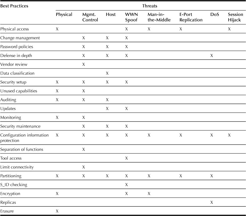
Table 33.1 summarizes the various best practices and the potential vulnerabilities they address.
Table 33.1
Best Practices and Potential Vulnerabilities
15. Encryption in Storage
Encryption is used to prevent disclosure of either stored or transmitted data by converting data to an unintelligible form called ciphertext. Decryption of the ciphertext converts the data back into its original form, called plaintext.
For environments that require even higher levels of security you can encrypt all transmissions (data and control) within the SAN utilizing a commercially available SAN encryption device. Also, for extremely sensitive data, host-based encryption should be considered. Most modern operating systems provide some form of encryption for their file systems. By utilizing these capabilities, all data is encrypted before it even leaves the host and is never exposed on the SAN in an unencrypted form.
The Process
Encryption simplifies the problem of securely sharing information by securely sharing a small key used to encrypt the information. In a two-party system, a process similar to these steps would be followed.2
1. Alice and Bob agree on an encryption algorithm to be used.
2. Alice and Bob agree on a key to be used for encryption/decryption.
3. Alice takes her plaintext message and encrypts it using the algorithm and key.
4. Alice sends the resulting ciphertext message to Bob.
5. Bob decrypts the ciphertext message with the same algorithm and key as the original encryption process.
6. Any change in the key or encryption algorithm has to be agreed on between Alice and Bob. The process of converting to a new key or algorithm requires decrypting the ciphertext using the original key and algorithm and reencrypting with the new key and algorithm. It is important that the key management system used securely preserves the old key for as long as the data retention policy for that data prescribes. Premature destruction of the key will result in loss of data.
The secure exchange of data in a two-party system is typically accomplished using a public/private key mechanism. Protecting data at rest, however, is best handled with a symmetric (private) key because the data is accessed from fixed and/or known locations. Typically one host would use the same algorithm and key to encrypt the data when writing to disk/tape and to decrypt the data when reading from disk/tape. In the case of multipathing or situations in which multiple applications from different nodes will access the data, centralized key management is essential.
Throughout the remainder of the chapter, only symmetric-key encryption will be discussed and will be referred to simply as encryption. Symmetric-key encryption, as noted, refers to the process by which data is encrypted and decrypted with the same key. This method of encryption is more suited to the performance demands of data path operations. Asymmetric-key encryption refers to the process where encryption is performed with one key and decryption is performed with another key, often referred to as a public/private key pair. Asymmetric-key encryption is not well suited to encrypting bulk data at rest due to performance constraints and manageability.
Encryption Algorithms
The algorithm used can be any one of a variety of well-known cryptosystems described in the industry. The U.S. Federal Information Processing Standards (FIPS) document the Advanced Encryption Standard (AES3) and specify it as the industry-standard algorithm in the United States. AES is the most common algorithm implemented in the current encryption methods described as follows. Triple-DES (Data Encryption Standard) is still a certified algorithm by the National Institute of Standards and Technology (NIST) and may be used but is not recommended.4
Encryption algorithms typically operate on block lengths of 64 to 128 bytes. To encrypt longer messages an encryption mode of operation may be used, such as:
The CBC, CTR, and GCM modes of operation used for encryption require the use of an initialization vector (IV), or nonce. The IV is a seed block used to start and provide randomization to the encryption process. The same IV and key combination must not be used more than once. XTS is the only one of the four that does not require an IV but instead has a second key called the tweak key.
In the event the length of the message to be encrypted is not a multiple of the block size, it may be required to pad the final block.
Key Management
The protection potentially afforded by encryption is only as good as the management, generation, and protection of the keys used in the encryption process. Keys must be available and organized in such a fashion that they can be easily retrieved, but at the same time, access to keys must be tightly controlled and limited only to authorized users. This attention to key management must persist for the lifetime of the data, not just the lifetime of the system that generates or encrypts the data. Generation of keys should follow some simple guidelines:
• The key generated must be random, for example, as specified by FIPS 186-2.5 There can be no predictability to the key used for encryption; pseudorandom number generators are not acceptable for key generation.
Once the keys are generated, their protection is crucial to guaranteeing confidentiality. This requires the following:
• Secure access to the key management solution. The key management solution must provide a method to guarantee that unauthorized access to keys is restricted. This access restriction should also extend to the facility for generating and managing keys. This can be accomplished via a number of mechanisms including secure Web, smart cards, or split key arrangements. The key management solution must also protect against physical tampering as outlined in FIPS 140-2.6
• Backup and recovery facilities for configuration and key information. This information itself must be encrypted and stored to a secure backup medium (for example, a smart card). The keys used for encryption must never be visible in plaintext outside the key management solution and, under most circumstances, should not be visible at all. For additional security, the recovery of the configuration/keys should be performed by a group of security administrators. This eliminates the potential for misuse due to corruption of a single administrator and utilizes a group key recovery model where M of N (that is, 2 of 3, 3 of 5, and so on) or a quorum of administrators is needed to reconstruct an encrypted configuration.
• The ability to apply high availability and business continuity practices and protocols to key stores.
• The ability to store keys and identify where they have been used for the lifetime of the data. This covers data that is written to tape and that may be read up to 30 years later.
• Integrity checking of keys. This is particularly important if there are no integrity checks on the data.
• Comprehensive logging and regular auditing of how and when the keys are used.
Key management can be distributed or centralized. A common implementation of these requirements is a key management station that can reside either online with the encryption engine or out of band via TCP/IP. The key management station provides a centralized location where keys can be managed and stored securely and meet the stringent standards of FIPS 140-2. At this point, there are very few certified, standalone key management systems.
Configuration Management
In configuring any of the methods for encrypting data described here, there are several common steps that need to be executed. The unit to be encrypted needs to be identified (for example, record, file, file system, volume, tape) and an associated key needs to be generated. This configuration information needs to be recorded, securely transmitted to the encryption engine, and securely stored for the lifetime of the encrypted data.
To ensure access to the encrypted data, the configuration must account for all paths available to the data and identify which applications, hosts, or appliances will access the data through those paths. Each needs access to the algorithm and key to be able to read/write uniformly from each path. In addition, replicas (for example, snaps, clones, and mirrors) need to be identified and associated with the original source data to ensure that they can also be correctly decoded when read.
16. Application of Encryption
Encryption is only one tool that can be applied as part of a comprehensive information security strategy, and as such, should be applied selectively, only where it makes sense. Determining exactly where and how this takes place begins with an assessment of risks to the data, the suitability of encryption to address the risk, and then, if appropriate, the options for deployment of the technology.
Risk Assessment and Management
Risk assessment is a calculation that requires three key pieces of information: the number and nature of threats, the likelihood of a threat being realized in the form of an attack, and the impact to the business in the event the attack succeeds. Let’s consider these in the context of a decision of whether it is appropriate to deploy encryption technology.
As administrators manage the flow of data from application to storage, they need to understand the nature of possible threats to the data and the likelihood of occurrence. These threats may take the form of:
These threats may occur at any point from where the information is generated to where it is stored. For each of these threats, an evaluation must be made as to the likelihood of attacks occurring and succeeding in light of existing protection measures. If any attack is determined to be likely, the value of the information subject to threat must be also considered. If the value to the business of the data being threatened is low, it ultimately may not warrant additional protection.
For those risks deemed to be significant, another calculation is required: are the tradeoffs of the proposed solution (in this case, encryption) worth making in context of the level of threat to the data. Considerations should include:
In this case, by restricting access to the information via authentication and authorization, the administrator can identify who has rights to use the information as well as who has attempted to use the information. Access privileges can be granted at various points in the information flow: at the application, operating system, network, and storage platform layers. If these measures are deemed insufficient, encryption might provide another layer of defense.
Modeling Threats
To make this process more specific to the problem at hand, Figure 33.1 illustrates some of the risks to data in the enterprise. By understanding the attacks that can occur, administrators can determine where encryption may help to protect data and where it would not be applicable.
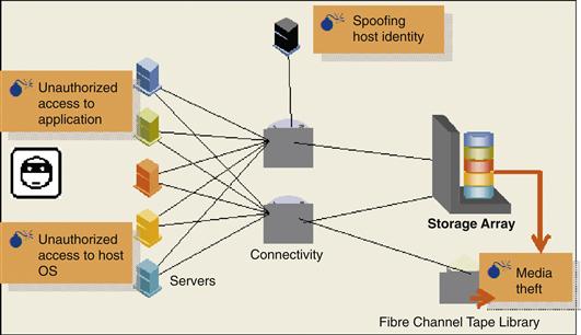
Figure 33.1 Threats to plaintext customer data.
Figure 33.1 shows the following:
• Encrypting the information at the application level protects against unauthorized viewing of information at the operating system (user) and network levels, as well as protects against media theft. However, encryption at this level will not protect against unauthorized access at the application level (as the information is decrypted at that point) nor root access from the operating system unless strong application access controls are in place.
• Encrypting the information at the host or operating system level protects against unauthorized viewing of information at the network level as well as protects against media theft. Encryption at this level will not protect against unauthorized access at the application or operating system level as the information is decrypted at that point. Access control technology would be required to provide additional security at the operating system and application levels.
• Encrypting the information in the network protects against unauthorized viewing of information from the encryption device to the storage device in the network as well as protects against media theft. Encryption at this level will not protect against unauthorized access at the application or operating system level or in the network up to the encryption device as the information is decrypted at that point.
• Encrypting the information at the device level protects against media theft. Encryption at this level will not protect against unauthorized access at the application or operating system level or in the network as all data external to the device is unencrypted.
Use Cases for Protecting Data at Rest
The following are some specific use cases that warrant deployment of encryption of data at rest. The primary use case is protecting data that leaves administrators’ direct control. Some examples of this situation include:
– Key-based data erasure for removed disk or array for return
– Data sent to a disaster recovery or remote site
• Protection of data between and in disaster recovery sites
– Consolidating data from many geographies to a single datacenter while still following each country’s security laws
– Using Type 1 encryption to share data between multiple secure sites
– Data in harm’s way (used for military applications such as planes, Humvees, embassies)
• Data extracts sent to service providers and partners
– Outsourcing scenarios where sensitive data resides in vendor systems
A second use case is protecting data from unauthorized access in the datacenter when existing access controls are deemed to be insufficient. Some examples of this situation are:
• Shared/consolidated storage used by numerous groups
– Sharing a single datacenter/array for multiple levels of security
– Sharing a platform between an intranet and Internet for consolidation
• Protecting data from insider theft (employees, administrators, contractors, janitors)
In addition, data encryption is mandated or recommended by a number of regulations. Deploying encryption will enable or aid in compliance. Selected examples of these regulations include:
• Sarbanes-Oxley Act. U.S. regulation with respect to disclosure of financial and accounting information.
• CA 1798 (formerly SB-1386). California state legislation requiring public disclosure when unencrypted personal information is compromised.
• HIPAA. U.S. health-care regulation that recommends encryption for security of personal information.
• Personal Information Protection Act. Japanese regulation on information privacy.
• Gramm-Leach-Bliley Act. U.S. finance industry regulation requiring public disclosure of personal data breaches.
• EU Data Protection Directive. European Union directive on privacy and electronic communications.
• National data privacy laws. Becoming pervasive in many nations, including Spain, Switzerland, Australia, Canada, and Italy.
Use Considerations
There are additional factors to consider when using encryption:
• Data deduplication at the disk level may be affected. Any good encryption algorithm will generate different ciphertext for the same plaintext in different circumstances. As a result, algorithms for capacity reduction by analyzing the disk for duplicate blocks will not work on encrypted data.
• Encrypted data is not compressible. Lossless compression algorithms could potentially expand as often as they compress encrypted data if applied. This will impact any WAN connectivity needing to transmit encrypted traffic.
• There is overhead in converting current plaintext data to ciphertext. This is done as a data migration project, even when it is done in place. Host resources, impact to CPU utilization, and running applications must be considered.
• An additional benefit to encrypting data at any level described is the ability to provide data shredding with the destruction of the key. This is especially efficient when there are multiple, distributed copies of the data encrypted with the same key. For the data to be considered shredded, all management copies of the key need to be destroyed for all security administrators, smart cards, backups, key management stations, and so on. Key destruction must follow similar guidelines as to the data erasure outlined in NIST SP 800-88.
Deployment Options
As we have seen, the use cases discuss why encryption would be used and the threats being protected against determine where encryption should be deployed. The following sections discuss in further detail deployments at each layer of the infrastructure.
Application Level
Perhaps the greatest control over information can be exercised where it originates, from the application. The application has the best opportunity to classify the information and manage who can access it, during what times and for what purpose. If the administrator has concerns/risks over the information at all levels in the infrastructure, it makes sense to begin with security at the application level and work down. In this case application-based encryption should be an option. Adding encryption at the application level allows for granular, specific information to be secured as it leaves the application. For example, a database could encrypt specific rows/columns of sensitive information (for example, Social Security numbers or credit-card numbers) while leaving less sensitive information unencrypted. Attempts to snoop writes-to-disk or to read-data directly from disk without the application decrypting it would yield useless information.
Encryption at the application level provides security from access at the operating system level as well as from other applications on the server as shown in Figure 33.2. The application would still need to provide user authentication and authorization to guarantee that only those with a need to know can access the application and the data. If the application lacks these strong access controls, application-based encryption will provide no additional security benefit. End-user activities with data after it is converted to clear text are potentially the highest security risk for organizations.

Figure 33.2 Coverage for application-based encryption.
There are some drawbacks to encrypting at the application level. First, encryption is done on a per-application basis. If multiple applications need encryption, each would have to handle the task separately, creating additional management complexities to ensure that all confidential data is protected. Second, application-level encryption solutions are typically software based. Encryption is a CPU-intensive process and will compete with normal operating resources on the server. In addition, the encryption keys will be stored in dynamic, nonvolatile memory on the server. If a hacker were to break into the server and find the keys, the information can be decrypted. Externalizing the encryption engine or key manager may address these issues at the expense of additional solution cost. An external key manager also enables clustered applications to share key information across nodes and geography (provided that each node can supply a secure channel from the server to the key manager.) If FIPS 140-2 compliance is a requirement for the encryption solution, an external appliance is typically used.
Application-based encryption also presents challenges in the area of rekeying. Any effort to rekey the data (to protect the integrity of the keys) will have to be done by the application. The application will need to read and decrypt the data using the old key and reencrypt and rewrite to disk using the new key. The application will also have to manage old and new key operations until all the previously encrypted information is reencrypted with the new key. This most likely will be done while the application is handling normal transactions, again presenting resource contention issues.
Another challenge occurs with the introduction of ediscovery solutions in the enterprise. Encryption at the application level will expose only encrypted information to other applications (including backup) and devices in the stack. Any attempt to perform analysis on the data will be useless as patterns and associations will be lost through the randomization process of encryption. To accomplish any analysis the ediscovery applications will need to be associated and linked to the application performing encryption to allow for a decryption of data at a level outside of the application, and a possible security risk could be introduced.
Application-based encryption (see Figure 33.2) must also account for variable record lengths. Encryption schemes must pad data up to their block size to generate valid signatures. Depending on the implementation, this may require some changes to application source code.
Application-based encryption doesn’t take into account the impact on replicated data. Any locally replicated information at the storage layer, that is, a clone, does not have visibility into the application and the keys and the application does not have visibility into the replication process. Key management can become more complex. In addition, compression in the WAN is impossible for remote replication of the encrypted information causing WAN capacity issues.
Host Level
Encrypting at the host level provides very similar benefits and tradeoffs to application-based encryption. At the host level, there are still opportunities to classify the data, but on a less granular basis; encryption can be performed at the file level for all applications running on the host (as shown in Figure 33.3). However, there are options for a host-based adapter or software to provide encryption of any data leaving the host as files, blocks, or objects. As with application-level implementations, the operating system must still provide user authentication and authorization to prevent against host-level attacks. If these strong access controls are absent, host-level encryption will provide no additional security benefit (aside from protection against loss or theft of media). If implemented correctly and integrated with the encryption solution, they can provide some process authorization granularity, managing which users should be allowed to view plaintext data.

Figure 33.3 Coverage for host-based encryption.
At the host level, encryption can be done in software, using CPU resources to perform the actual encryption and storing the keys in memory, or offloaded to specialized hardware. Offload involves use of an HBA or an accelerator card resident in the host to perform the actual encryption of the data. In the case of the HBA the encryption can be performed in-band and is dedicated to the particular transport connection from the host, that is, Fibre Channel. For an accelerator card approach, the encryption is done as a look-aside operation independent of the transport. This provides flexibility for host connectivity but increases the memory and I/O bus load in the system. In either case the host software would control the connection to the key manager and management of the keys.
There may be a need in the enterprise for the host-based encryption solution to support multiple operating systems, allowing for interoperability across systems or consistency in the management domain, something to consider when evaluating solutions. In addition, when encryption is implemented at the host level, there is the flexibility of being storage and array independent, allowing for support of legacy storage with no new hardware needed. Host-based encryption does present a challenge when coupled with storage-based functionality, that is, replication. If replication is employed underneath the host encryption level the host implementation must have the ability to track replicas and associate encryption keys, eliminating the need for users to manually manage the replication and encryption technology. As host encryption supplies encrypted data to the array, remote replication would transmit encrypted, uncompressible data. This would severely impact WAN performance.
As with application-based encryption, ediscovery solutions in the enterprise pose additional complexities. Encryption at the host level will expose only encrypted information to other hosts and devices in the stack, introducing the same challenges with analysis as those described in the prior section.
As encryption is performed at the host level, the data can be of variable record length. Similar to the application-based approach, the encryption solution can add information to the encryption payload to allow for a digital signature or cryptographic authentication. This would prevent a “man-in-the-middle” from substituting bad packets for the good encrypted packets from the host.
Network Level
If the threats in the enterprise are not at the server, operating system, or application level, but instead at the network or storage level, then a network-based appliance approach for encryption may work best. This approach is operating system independent and can be applied to file, block, tape, Fibre Channel, iSCSI, or NAS data. Encryption and key management are handled entirely in hardware and run at wire speed for the connection. The appliance presents an “unencrypted side” and “encrypted side” to the network. Encryption can be designated on a per block, file or tape basis and the keys maintained for the life of the data. Appliances available today are typically FIPS 140-2 level 3 validated.
There are two implementations for a network-based appliance design: store-and-forward or transparent. The store-and-forward design appears as storage to the server and a server to the storage, and supports iSCSI, Fibre Channel, SAN, NAS, and tape. An I/O operation comes to the appliance, is terminated, the data encrypted, and then forwarded to the destination storage device. This approach adds latency and as a result, some form of “cut-through“ ideally needs to be offered to minimize the impact of the device for nonencrypted traffic. In addition, to appear as both server and storage, the store-and-forward appliance either needs to spoof the identities of the attached devices or rely on robust security practices to counteract the attempts to circumvent the appliance. While there may be a latency penalty for encrypting data through the appliance, the store-and-forward-based design has the benefit of allowing the attached storage devices to be rekeyed in the background. This is performed with no disruption to host operations as all I/O operations to the storage are handled independently of the host. There may still be some performance impact to the rekeying process, depending on the I/O load on the encryptor.
The transparent approach provides a flow-through model for the data being encrypted, supporting Fibre Channel SAN and tape. The appliance inspects SCSI headers as data flows through the appliance and encrypts only the data payloads that match preset source/destination criteria in the appliance configuration. The latency associated with this approach is minimal. The transparent design does, however, have a drawback when the encrypted data needs to be rekeyed. Unlike the store-and-forward design, the device is essentially transparent in the data flow, requiring the host to perform the reads and writes required in rekeying the encrypted data. This process can be done by a separate host agent and could be performed while normal operations are in process.
For block-based implementations, the size of the encrypted data cannot increase. This means no additional information can be added to the encrypted payload (for example, a digital signature). This is not true for file or tape-based encryption where the record information may be variable. As noted in the discussion on standards, the IEEE is working to provide standards for encrypting block data at rest, in IEEE P1619.
There may be a need in the enterprise for the encryption to support multiple operating systems, allowing for interoperability across systems or consistency in the management domain. In addition, when encryption is implemented at the network level, there is the flexibility of being storage- and array-independent, allowing for support of legacy storage—at the cost of adding new hardware. Hardware in this case is added in increments of ports, typically two at a time, adding to the power, package, and cooling issues currently facing enterprises today. In addition, adding appliances in these increments can add complications in managing additional devices in the enterprise. Network-level encryption does present a challenge when coupled with storage-based functionality such as replication. If replication is employed underneath encryption at the network level, the implementation must have the ability to track replicas and associate encryption keys, eliminating the need for users to manually manage the replication and encryption technology. As network-level encryption supplies encrypted data to the array, remote replication would transmit encrypted, uncompressible data. This would severely impact WAN performance.
There are also implementations moving to use data integrity features as part of the protocols. Encryption in the network level (see Figure 33.4) would encrypt both the data and the data integrity, resulting in mismatches at this level of checking performed at the arrays.
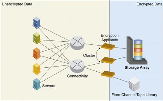
Figure 33.4 Coverage for network-based encryption.
Network-level encryption doesn’t take into account the impact on replicated data. Any locally replicated information at the storage layer, that is, a clone, does not have visibility into the network device management and the keys and the network device does not have visibility into the replication process. Key management can become more complex and more manual. In addition, compression in the WAN is impossible for remote replication of the encrypted information causing WAN capacity issues.
Device Level
Encryption at the device level—array, disk, or tape—is a sufficient method of protecting sensitive data residing on storage media, which is a primary security risk many organizations are seeking to address. All data written to the device would be encrypted and stored as such and then decrypted when read from the device. Encryption at this level would be application and host independent and can be transport independent as well. When addressing media theft, the granularity for encryption, and keys, can be at the disk or tape level. As demonstrated in Figure 33.5, exposure for unencrypted data is increased as compared to the previous implementation examples.

Figure 33.5 Coverage for device-based encryption.
Array-Level Encryption
There are a number of design points for encryption in the array, that is, at the disk or controller level. Design considerations for encryption include the interfaces to the array, software support, performance, FIPS validation, key management, and encryption object granularity to name a few. The intent is to have the encryption implementation transparent to the hosts attached while protecting the removable media. The connected hosts may not be knowledgeable of the encryption implementation but may be with respect to management and performance. All aspects of the design must be considered.
One possible approach is to implement the encryption in the disk drive, at the back end of the array. Some points to consider:
• As encryption is on a per-drive basis, the computes required are included in the drive enclosure, allowing for a scalable solution, adding encryption with every unit. The downside to this is cost to the functionality that is added with every unit. So while performance scales, so can cost.
• Customers might be unable to verify that encryption is enabled and functioning on the array, because data is always plaintext when it is external to the disk drive.
• Any approach to encryption at this level would also require interoperability of the encryption implementation across drive vendors to maintain flexibility and customer choice.
• Bulk drive encryption would not provide key granularity at the LUN/device level, which in many cases would eliminate the possibility of erasing specific confidential projects via key deletion.
• Last, as driven by the Trusted Computing Group, encryption at this level may follow a different path for validation, an alternative to FIPS 140 yet to be developed. Without a standard to evaluate it is impossible to understand the disk drive encryption validation proposal.
Another approach might be to implement encryption in the I/O controller connected to the disk drives. Some points to consider for this potential implementation are:
• Encryption is on the interface level and is required to support full wire speed versus interface speed in the drive approach.
• The cost model would be based on a single controller versus tens of drives connected to a single controller.
• The controller approach has the ability to perform encryption at the I/O level, allowing the granularity for key management to be at the LUN or disk level. This approach allows for future support of LUN-based erasure and logical data management.
• The controller approach is drive-independent, not relying on any specific vendor or interface, allowing for all standard tools and failure analysis to be performed.
• In supporting encryption at the controller level the crypto boundary can be well defined, allowing for FIPS 140-2 validation.
• Encryption and key control would be separate from the disk drive containing the encrypted data. This allows the customer to validate the encryption functionality is working and not be concerned with keys leaving with a removed disk drive.
An alternative to the encryption option for the protection against media theft is data erasure. It addresses the same primary use case: protection of disk media containing sensitive data and is available today, as erasure services (for removed drives) and software (for in-frame erasure). Erasure overwrites data multiple times, in accordance with the Department of Defense specification 5220.22-M, removing the data from the media. One consideration is that a minority of drives are not erasable for mechanical reasons.
Tape Encryption
As part of normal operations, data is frequently written from storage devices to tape for backup/data protection or third-party use. Data on tape cartridges becomes susceptible to theft or loss due to the size of the tape cartridge and quantity of the number of tapes to track during normal backup operations. To best protect the data on tape against unintended/unauthorized viewing, it can be encrypted. There are several approaches to encrypting tape as part of the backup operation:
• Reading encrypted data from application/disk and writing as encrypted data to tape
• Reading unencrypted data from application/disk and encrypting as part of the backup application
• Encrypting any/all data sent to tape via an encryption appliance in the network
• Encrypting any/all data written to the tape via an encrypting tape library or tape device
Tape encryption also presents key management challenges. Tapes may be stored for an extended period of time before an attempt is made to recover information. During the normal process of managing encrypted data, the application may have rekeyed the data on disk, updating all data on the disk to use a new key. This process would present the application with active data using one key and data on tape using an older key. The application must be therefore be able to manage keys for the lifetime of the data, regardless of where the data is stored. The following are tape encryption deployment options.
Application Level
Backup is typically another operation running on a host as a peer to the encrypting application. Any peer application or process will read data from the storage array as encrypted data. This allows the backup process to write already encrypted data to tape without having to perform the encryption itself. It will, however, prevent data compression during the backup process, as encrypted data is not compressible. Because typical compression ratios reduce data volumes anywhere from 2:1 to 4:1, this will impact performance of the backup process if a large amount of bulk data is encrypted.
Applications providing encryption can also provide access for authorized peer applications to read data in encrypted or unencrypted form. This would allow a backup application to read data in unencrypted form and allow for compression followed by encryption to be performed as part of the backup process.
Operating System/Host
Backup is another process on the host when using host-based encryption. The encryption process in the host operating system has the option of allowing the backup process to read data in encrypted or unencrypted form. If the authorization module determines that the backup process can read plaintext data, backup will receive decrypted data to be sent to tape. Encryption will also need to be performed by the backup application to allow for writing secure tapes. The backup process could take advantage of compression in this data flow. If the backup process is not allowed to view decrypted data, it will read encrypted data from disk and write it as such to tape. As in the application-based approach, compression may not be able to be utilized on this encrypted data, creating potential performance issues. In addition, the encryption engine for the host will have to maintain the keys for the lifetime of the data to ensure that decryption can take place in the event a restore from tape is needed.
In the Network
If an encryption appliance is placed in the network, backup can be handled in one of two ways. If backup is volume based, any data read from the storage array may already be encrypted. The backup application will read the encrypted data and write it directly to tape. In this scenario, there would be no benefit of compression in the data path. If the backup is file or incremental based, the backup process would read the data through the appliance, decrypting it in the process, and could then write the data to tape. To provide encryption, a tape encryption appliance would be positioned in front of the tape device, compressing and encrypting the data as it is written to tape. The tape encryption appliance would manage the keys for the lifetime of the tape.
At the Tape Library/Drive
Data can be encrypted at the tape drive level, independent of the backup process and application software. All encryption is performed at the device, or library, when data is written to the tape and decryption performed at the drive when data is read from the tape. The backup application deals with nothing but plaintext data. The tape drive or library can be the management interface to the key manager, requesting generation of keys for new tapes written and retrieval of keys for each tape read. Association of keys to tapes is managed at the key manager appliance. In some cases the key manager can be integrated to work cooperatively with a volume pool policy defined with backup application. Jobs directed to use tapes in a pool associated with this policy begin with a request by the drive or library for an encryption key only when the backup or restore job uses tapes in this volume pool.
17. Conclusion
Security is a complex and constantly evolving practice in the IT industry. Companies must recognize that threats to information infrastructures require vigilance on the part of IT managers and the vendors they rely on.
The management, integrity, and availability of your data should be your first priority. As this analysis has shown, basic security best practices can be implemented to greatly increase the security of your Fibre Channel SAN and the data it contains. The available avenues of attack are minimized by carefully controlling access to resources, both physically and logically.
While many storage vendors are making extensive investments in the security of their SAN products, they also recognize that it is impossible to predict every possible current and future combination of threats that might impact an IT environment. Ensure that your vendor constantly monitor changes and advances in security threats and technology, and updates its products with new features and functionality to address any issues that might impact the data on your SAN.
Encryption is a tool that can be used to protect the confidentiality of the information in the enterprise. To understand if and how an encryption solution should be deployed, administrators need to understand and assess the risks of unauthorized access and disclosure at each point of the information flow. They must also understand how deployment of encryption technology may add risk to other areas of the business, including complexity added to management, and risks to availability of encrypted data to authorized users. Data unavailability can come from something as simple as key management, which is perhaps the most important factor to consider in implementing an encryption solution. Encryption should be considered as part of a total security solution, but not the only solution; administrators need to take advantage of protection options at all levels of the information flow and architecture. Two general issues that are present across encryption implementations are:
• The conversion of plaintext to ciphertext when encrypting data for the first time or ciphertext to ciphertext when encrypting with a new key. Both are done as a data migration project, even when it is done in place. Host resources, impact to CPU utilization, and running applications must be considered.
• The replication of encrypted data across the WAN. Encryption, if done correctly, produces random, uncompressible data that will impact the utilization of remote connectivity.
Table 33.2 summarizes the various deployment options.
Table 33.2
Summary of encryption approaches

References
1. Blaul JC. Storage Security. Wiley Publishing, Inc. 2003.
2. Dwivedi H. Securing Storage: A Practical Guide to SAN and NAS Security. Pearson Education, Inc. 2006.
3. B. King, LUN Masking in a SAN, Aliso Viejo, California, October 8, 2001.
4. J. McDonald, Security Considerations for Fibre Channel Storage Area Networks, Hopkinton, Massachusetts, June 5, 2005.
5. C. McGowan, Approaches for Encryption of Data-at-Rest in the Enterprise, Hopkinton, Massachusetts, September 10, 2008.
1An attack in which an attacker is able to read, insert, and modifymessages between two parties without either party knowing that thelink between them has been compromised.
2N. Ferguson, Practical Cryptography, Wiley Publishing, 2003.
3FIPS 197, http://csrc.nist.gov/publications/fips/fips197/fips-197.pdf.
4FIPS 46-3, http://csrc.nist.gov/publications/fips/fips46-3/fips46-3.pdf.
5http://csrc.nist.gov/publications/fips/fips186-2/fips186-2-change1.pdf.
6http://csrc.nist.gov/cryptval/140-2.htm.
7An attack in which a third party tries to mislead participants in a privileged conversation using forged information.
8A form of network attack in which a valid transmission is maliciously or fraudulently repeated or delayed.