5.15. An MPSOC-Design Tool
Configurable, extensible processor cores and pre-configured processor cores are the backbone of high-performance MPSOC architecture. The availability of automatic techniques to derive instruction extensions for configurable processor cores allows the final processor-configuration process to be delayed till almost the end of the system-design process. Of course, pre-configured processors used in the MPSOC’s design need no additional configuration.
By automatically generating a configuration and extended ISA for the configurable processor cores early in the MPSOC’s design, a lower bound on the MPSOC’s performance envelope can be established for the initial task mappings onto the MPSOC’s processors, which can be quickly redone whenever changing requirements or quantitative simulation results lead to changes in the task mapping.
Manual improvements made to the configurable processors in the final MPSOC architectural design can create additional performance headroom and allow last-minute processor load balancing and power optimization through the strategic reallocation of some tasks. This refinement process can also help reduce the operating clock frequency for one or more on-chip processor cores by getting more work done per clock cycle, which in turn can lead to an operating-voltage reduction for the MPSOC, which reduces the chip’s operating power.
Tensilica is developing just such a processor-IP centric-design methodology that is specifically oriented toward Tensilica’s Xtensa and Diamond processor cores. This design methodology is based on the function-architecture co-design scheme first proposed in 1997. Early versions of the design tools associated with this design methodology appear in Figures 5.20–5.22.
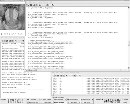
Figure 5.20 also illustrates a table-driven user interface for capturing an MPSOC’s system structure. Although future MPSOC-design tools may provide graphical, diagrammatic ways of capturing system structure, and this may be a desirable capability in the long term, the presently implemented tabular method captures MP system structure remarkably well.
Figure 5.20. One table-driven page can capture an MPSOC’s high-level architecture so that quantitative simulation results can be produced.

Modeled at the transaction level, processors and other system components have a reasonable and controlled number of high-level interfaces. Stitching these interfaces together by choosing links from drop-down boxes in a table is sufficient for MP architectures comprising a few tens of key system components. Support for hierarchical subsystem structures with continued use of high-level interfaces between subsystems permits continued use of tabular entry and allows graphical editing of system structure as MP systems grow in complexity.
The captured system structure; the configurable and pre-configured processor models; and the models for other system-level components such as memories, routers, queues, arbiters, and other devices can be used to automatically generate two kinds of system-simulation models, as shown in Figure 5.21.
Figure 5.21. Cycle-accurate SystemC models and instruction-accurate fast functional-simulation models can be automatically generated from system high-level system descriptions entered in tabular form.
The first model is a cycle-accurate SystemC model of the subsystem described via the entry table shown in Figure 5.20. This subsystem model has extensive tracing capabilities and can be linked to other SystemC models that represent other portions of the SOC, as long as compatible transaction-level models are used. Alternatively, appropriate wrappers or adapters placed around incompatible models based on different notions of “transaction” can bring compatibility to an incompatible mix of SystemC models.
Such a cycle-accurate, transaction-based system model runs at least two orders of magnitude faster than the equivalent RTL simulation. Faster simulation means better, more thorough simulation because there’s more time to try different loading scenarios and operating conditions. Tracing facilities allow system-level transaction performance to be monitored on a statistical basis. From this performance analysis, system designers can derive statistics on overall system throughput and latencies. The tracing facilities also allow detailed transaction-level debug to take place using a visual depiction of the traces.
Figure 5.22 shows a trace file generated in the course of cycle-accurate system simulation. This result display can be used to monitor and debug system-level transactions and to determine the systemic cause for system performance problems. Transaction requests can be examined as they ripple through a hierarchy of devices and their responses analyzed. Stalls, contention, and unusually long transaction-response delays can be visually highlighted as exception conditions.

Tensilica’s system-level design methodology provides system-level design capabilities and models some abstract communications mechanisms. It can map abstract FIFO communication channels into a variety of physical implementations supported by Xtensa and Diamond processor cores including direct hardware queues and shared memories with various locking mechanisms. The methodology can also generate instruction-accurate, fast-functional SystemC models. These models run 10–100× faster than cycle-accurate SystemC simulations for MP systems. Such fast models can only be run under a variety of restrictions but they are particularly useful for software developers, as long as careful attention is paid to the speed-accuracy tradeoff being made.
Fast simulation models require appropriate synchronization mechanisms to be effective. For example, a FIFO queue of fixed depth, which might be used in a cycle-accurate simulation, can stall processor execution for many cycles in an unbalanced system—a processor will stall when it tries to push data into a full FIFO or when it tries to pop data from an empty FIFO. It may be appropriate in such cases to use a FIFO buffer model with a queue depth that’s effectively infinite rather than fixed and finite to avoid such stalls in fast simulations, which can communicate with the infinite buffer using direct method calls rather than treating the FIFO as an explicitly modeled device. The behavior of such a modeled system will be functionally accurate for normal operation and thus will allow software development and verification to proceed without getting ensnared in secondary design issues such as optimal queue depths.