
The switcher is the heart of the studio.
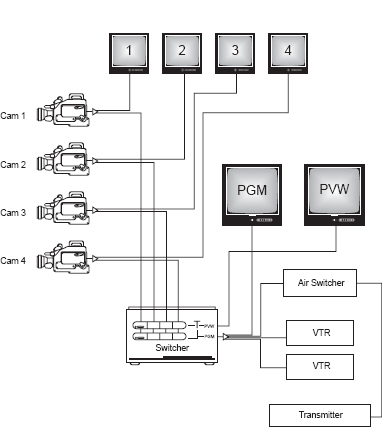
Production Switcher Flow Diagram
Take a look at the flow diagram of a switcher integrated into a simple video system. This switcher is very basic, and a lot has been left out to keep things as simple as possible. As you can see, this system has four cameras. Now follow the outputs of each camera. In each case, the output goes to a distribution amplifier and from there one output goes to a monitor and another goes to the production switcher.
Switcher Buses
You'll notice that at the switcher there are two rows of buttons, each row a duplicate of the other. These rows of buttons are called buses. They're what give you the ability to cut and dissolve between cameras.
Switcher Outputs
The switcher has two outputs. The preview (PVW) output allows the director to see the next shot before it is used. The program (PGM) output is what is intended to be recorded or transmitted. In this example, the final output is both recorded and transmitted.
The preview output is going to a preview monitor for the director's use. The program output is going to a distribution amplifier, and from there one output goes to the program monitor and another one goes to the on-air switcher, where it is fed to the transmitter. The other two program DA outputs are going to videotape recorders (VTRs) where the show is recorded.
Production switchers will usually have a master program bus (PGM). Whatever is punched up on this row of buttons will be the picture being recorded and sent out to the viewers. Below the program bus will be a preview (PVW) or preset (PST) bus. Next to these two rows of buttons will be a “Take” button and a T-shaped handle. Whatever the director wants to see next will be “punched up” on the PVW/PST bus. Pushing the “Take” button will create a cut from what was on the PGM bus to what is on the PVW/PST bus. Moving the T-shaped handle will create a dissolve between the two video sources. In either case the sources on the PVW/PST bus will swap positions or flip-flop with the source on the PGM bus.
This is a simplified diagram of a very basic system, but if you study it, you'll get a good idea of how the basic components are integrated.
Switcher flow diagram