Camera flow diagrams illustrate video signal paths
Camera Flow Diagrams
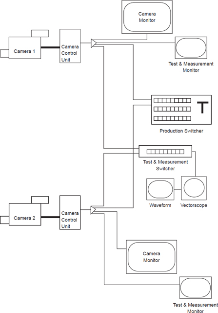
Take a look now at the flow diagrams for the cameras. As previously mentioned, this diagram traces output from the cameras to their ultimate destinations. The camera head is labeled Studio Camera 1, and its output goes to its CCU (camera control unit). The CCU has outputs labeled Video Out, R (red), G (green), and B (blue). The Video Out output is a fully encoded color output and goes from the CCU to a video distribution amplifier (VDA). The first VDA output goes to the main monitor wall. This is the monitor that the director looks at to decide what picture to put on the air. The second VDA output goes to the video control area. This allows the engineer to look at the various video sources to check for problems and fix them before they get too serious. The third VDA output goes to the production switcher. This allows the technical director to “punch up” the picture that the director has selected. The final VDA output goes to the patch panel. Patch panels are like switchboards; they tie all of the system components together.
The RGB outputs are the individual color components of the picture and may be kept separate throughout the studio that is set up for component operation (to be discussed later). The component outputs may also be routed to certain special effects units such as a chroma keyer.
Dropping down to camera 2, you see that it is just the same as camera 1. If there were additional cameras in the system, camera 3, 4, ... would be the same as 2. Whether you're in a small 2-camera studio at a school or are using 48 cameras at the Super Bowl, they would all be set up in a similar manner.