
Operations Manager (OpsMgr) 2007 can provide solutions when running on a single server or it can scale to multiple servers, depending on the specific requirements of your organization. This chapter offers insight for deploying OpsMgr in environments that require redundancy, multihoming, connected management groups, or gateway servers. The chapter also provides performance recommendations to consider when you are implementing complex configurations of OpsMgr.
Many management server configurations incorporate a “complex” OpsMgr environment. These configurations include multilocation deployments, connected management groups, multihomed deployments, and redundant configurations. When designing Operations Manager 2007 configurations, we always ask six key questions during the Assessment phase:
These questions affect how you configure your management group and the complexity of your environment.
To discuss multilocation deployments, we will use our fictitious company Odyssey. Odyssey’s campus includes a corporate Plano location. Plano’s OpsMgr implementation supports 500 servers, with the load split between two management servers named Hydra and Hornet, and a database server named Thunder. Odyssey also has a Carrollton location, with 250 servers.
A common practice is to have at least two management servers in your primary location (which typically is where the database server resides) and to split the agents between the management servers to provide load balancing and redundancy when a management server is not available.
Although only one Root Management Server (RMS) can exist in a management group, we suggest you always have at least two management servers (including the RMS) in your primary location. You should also be aware that because there is no data compression between the management server(s) and the Operational and Data Warehouse databases, these components are best placed on the same network or set up to communicate over a fast link.
Odyssey has installed a wide area network (WAN) link between the Plano and Carrollton locations and is placing an additional management server in Carrollton, as we show in Figure 10.1. The management server (Talon) in Carrollton communicates with the database server in Plano, which contains the Operations database. Using a local management server keeps each agent in Carrollton from needing to communicate with a management server in Plano, which reduces bandwidth requirements between the agents and the management server.
For multilocation deployments, we generally recommend at least one management server in each location to minimize WAN traffic and bandwidth requirements. Although the traffic between the agent and the management server is compressed, there can still be quite a bit of activity.
We can use several approaches for designing a solution for Odyssey. One implementation utilizes connected management groups, whereas the one Odyssey decided to implement uses a single management group, with a centralized database and multiple management servers to localize its server management. A potential downside of this configuration is that one of the management servers (Talon) accesses the Operations database across a WAN link. You would want to allow for this additional traffic when analyzing your WAN requirements.
One way to disperse agent traffic is by placing additional management servers in various locations; an alternative is to deploy multiple management groups. Implementing multiple management groups introduces complexity, and you will want to consider this option carefully. As discussed in Chapter 4, “Planning Your Operations Manager Deployment,” you should use multiple management groups in situations such as the following:
You are exceeding management group support limits. (Although the number of agents is actually a function of available resources and there is no hard limit on the number, we recommend no more than 5000 managed computers in a management group.)
There is a requirement to separate administrative control (application support in one group, web application support in another group).
You have multiple locations with servers at each location. Multiple locations is not an absolute criterion for creating additional management groups, but it’s something to consider.
You have network environment restrictions (for example, minimal bandwidth or reduced network traffic requirements).
Note: Sizing Your Management Groups
You may want take into consideration the size of your Operations database when planning your management groups. Although there technically is no limit to the size of the database, there are known issues when using a database larger than 40GB. In addition, some DBAs are unwilling to support a database larger than 100GB, which can put a serious crimp in your design if you have 6000 agents! We recommend not exceeding 40GB as a best practice, and we have heard Microsoft CSS (Customer Service and Support) recommending 30GB as a preferred maximum.
If you create a second OpsMgr management group, you must decide how to best separate agents across the two management groups. Common approaches include
Splitting the agents geographically.
Splitting the agents by departments. This comes into play when an IT department may have control over its group of servers but no control over a second IT department’s servers.
Allow for growth in the number of agents within your management groups and do not attempt to configure more than 5000 agents (the maximum supported by Microsoft) in a single management group.
When you have more than one management group, you can define a relationship between them. We call these connected management groups. When you connect management groups, you are not actually deploying new servers; rather you are defining a top-tier or local management group that will have access to the Alerts and Discovery information in a bottom-tier or connected management group. This capability allows you to use a single console to view and interact with the alerts and other monitoring data from multiple management groups. Using the Operations console, you can also execute tasks on the monitored computers of the connected management groups.
Establishing connected management groups requires that each management group is functional and able to communicate with each other using DNS name resolution. As we discussed in Chapter 4, management group names need to be unique so that they can be connected in this way.
If trust relationships are in place and the SDK service account has permissions in the connected management group, you can use the OpsMgr SDK account, which is the default configuration.
Establishing connected management groups allows you to see alerts from both the management group you originally were accessing and the alerts available through the connected management group. We discuss setting up this process in Chapter 22, “Interoperability.”
As discussed in Chapter 5, “Planning Complex Configurations,” a multihomed configuration exists when the agent on a server reports to more than one management group. Each management group has its own Operations database and management server(s). (An agent reporting to multiple management servers within a single management group is not multihomed.)
Multihoming allows you to distribute monitoring across multiple technical teams. For example, your security administrators can monitor a computer for security issues in one management group using ACS while your Exchange administrators can monitor the same system because it runs Microsoft Exchange. By installing multiple management groups and then multihoming agents, you can distribute monitoring requirements across multiple teams, thus enabling each team to use its own OpsMgr administrators and rule configurations. Because each management group has its own database, you can change rules in one group without affecting rules in another group.
A multihomed agent can report to a maximum of four management groups in a supported configuration. Each management group has its own set of processing rules and configuration information. A multihomed agent processes each set of processing rules independently, so there is no conflict in applying rules.
You deploy multihomed agents using the same mechanisms we discuss in Chapter 9, “Installing and Configuring Agents.” To install a multihomed agent, just install the agent in one management group and then install it in the second management group. You can install the agent using the Discovery Wizard in the Operations console or by manual agent installation, as well as any of the other techniques discussed in Chapter 9.
Figure 10.2 shows a sample multihomed configuration with two management groups (GROUP1 and GROUP2) reporting to two different management servers.
As you can see, management servers and management groups can be implemented in a variety of ways. Evaluate these options and consider the best course of action based on your specific business requirements.
In Chapter 6, “Installing Operations Manager 2007,” we discussed the process for installing a gateway server. Operations Manager 2007 requires mutual authentication between the agents and the management server, and between the gateway and the management server to which it reports. Mutual authentication increases the security of the communication model within OpsMgr by requiring the systems to authenticate.
OpsMgr supports two different methods to provide this authentication. The first method is Kerberos. You can use Kerberos authentication within the same Active Directory domain, or within domains having a two-way trust relationship with the domain with the management server. Kerberos is not available for systems in a workgroup or untrusted domain.
Operations Manager 2007 can also use x.509 certificates to provide the authentication required for mutual authentication, although there is more overhead here than with Kerberos. Gateway servers use certificate authentication to provide the mutual authentication to monitor systems that are part of a workgroup or an untrusted domain.
Figure 10.3 shows a configuration that uses both Kerberos and certificates for authentication. It includes the following components:
The agents in the Active Directory domain Odyssey.com use Kerberos authentication because they are part of the same (or two-way trusted) domain.
The agents in the untrusted Continent.com domain use a gateway server, which they locally communicate with from the agent using Kerberos.
The gateway server communicates with the management server in the Odyssey.com domain, using certificates for authentication.
The agents in a workgroup configuration each have certificates configured to communicate with the gateway server.

This configuration should be an uncommon one, because it uses all the major configurations available (same domain, untrusted domain, and workgroup) but shows an example of the variety of ways which these authentication methods can be used within Operations Manager 2007. You may have occasion to monitor agents in a workgroup in a DMZ that does not have its own domain.
It is also possible to monitor agents in a workgroup configuration without deploying a gateway server. This is possible by configuring certificate authentication directly from the agent to the management server. This approach is often used when there is no requirement to minimize the points of communication (using a gateway provides a single communication point from one set of agents to the management server) or when there are budget restrictions that remove the ability to add another (gateway) server.
Note: About the Gateway Server
You will install a gateway server in an environment that does not have a trust relationship with the domain containing the RMS. A gateway server is used as a centralized point for agent communications between the agents and their management server. You will find this component in untrusted domains or workgroups.
Additional steps are required on a gateway server to generate and import certificates and to approve the gateway server. At a high-level, the steps are as follows:
Request certificates (this will be for any computer in the agent, gateway server, and/or management server chain).
Import the certificates using MOMCertImport.
Run the Microsoft.EnterpriseManagement.GatewayApprovalTool.exe approval tool to initiate communication between the management and gateway servers.
Chapter 11, “Securing Operations Manager 2007,” includes a full discussion on generating and importing certificates.
After generating and importing your certificates (refer to Chapter 11), perform the following steps:
Copy the Microsoft.EnterpriseManagement.GatewayApprovalTool.exe approval tool from the Operations Manager installation media in the SupportTools folder to the Operations Manager 2007 installation folder (%ProgramFiles%System Center 2007 Operations Manager by default) on the management server.
On the management server targeted during your gateway server installation, log on using an account that is a member of the Operations Manager Administrators role.
Open a command prompt and navigate to the %ProgramFiles%System Center Operations Manager 2007 folder or the folder to which you copied the approval tool (Microsoft.EnterpriseManagement.GatewayApprovalTool.exe).
At the command prompt, run
<LINELENGTH>90</LINELENGTH>Microsoft.EnterpriseManagement.GatewayApprovalTool.exe /ManagementServerName=<ManagementServerFQDN> /GatewayName=<GatewayFQDN> /Action=Create.
Successfully executing this utility returns a message that the approval of server
<GatewayFQDN>completed successfully. (To later remove the gateway server from the management group, use the same command but change the syntax such that/Action=delete).To validate that the approval occurred correctly, open the Operations console and navigate to the Administration -> Device Management -> Management Servers folder to see the gateway server in the list.
Tip: Security Considerations for the Gateway Approval Tool
The Gateway Approval Tool attempts to write data to the Operations Manager database, so you will want to ensure that the account you log in with to use the Gateway Approval Tool has write permissions to that database.
For example, you could run the Gateway Approval Tool using the same credentials you specified for the SDK and Config account.
The suggested approach for redundancy with the Gateway Server Component is installing multiple gateway servers and distributing the load of agents between the gateway servers, such that no server is monitoring more than 200 agents at any point in time. This approach provides a way for agents to report to a different gateway server if their primary server is not available.
There is an additional level at which we want to consider redundancy. Gateway servers are configured to communicate with a specific management server. To provide redundancy at this level, we need to be able to configure the gateway servers to fail over between management servers as needed.
To configure gateway server failover between management servers, log in to the management server using an account that is a member of the Administrators role for the management group and open the Command Shell (Start -> All Programs -> System Center Operations Manager -> Command Shell).
Within the Command Shell, we can define the primary management server and failover management server for the gateway server. Perform the following steps:
To configure gateway server failover to multiple management servers, we first must define the variables used by the Set-ManagementServer command:
<LINELENGTH>90</LINELENGTH>$primaryMS = Get-ManagementServer | where {your filter here} $failoverMS = Get-ManagementServer | where {your filter here} $gatewayMS = Get-ManagementServer | where {your filter here}As an example, our environment has two management servers in the Odyssey domain named Hornet and Talon. We have a gateway server named Ambassador. The syntax to configure these filters would be:
<LINELENGTH>90</LINELENGTH>$primaryMS = Get-ManagementServer | where {$_.Name -eq 'Hornet.Odyssey.com' } $failoverMS = Get-ManagementServer | where {$_.Name -eq 'Talon.Odyssey.com' } $gatewayMS = Get-ManagementServer | where {$_.Name -eq 'Ambassador.Odyssey.com' }After defining these variables, we can use them within the Set-ManagementServer command using the following syntax:
<LINELENGTH>90</LINELENGTH>Set-ManagementServer -GatewayManagementServer: $gatewayMS -ManagementServer: $primaryMS -FailoverServer: $failoverMS
This process configures the gateway server to have a primary management server of Hornet and a failover management server of Talon.
You can find additional information for the technologies used with the gateway server:
Microsoft has provided a Certificate Services overview at http://technet2.microsoft.com/windowsserver/en/library/7d30a7ec-438f-41f8-a33a-f2e89d358b121033.mspx.
The Public Key Infrastructure for Windows 2003 is available at http://www.microsoft.com/windowsserver2003/technologies/pki/default.mspx.
SystemCenterForum has an excellent write-up on the gateway server and scenarios for it, available at http://systemcenterforum.org/wp-content/uploads/OpsMgr2007_Gateway_Config_v1.2.zip.
The “Management Server Configurations” section of this chapter listed six key questions you should consider during the Assessment phase. The third question—redundancy—is the key to determining whether or not this section of the chapter will be relevant to your environment.
If redundancy for Operations Manager is a business requirement, there are several different levels where you can apply redundant configurations. As an example, there may be a business requirement to have a highly available OpsMgr monitoring solution, but reporting may not require high availability. The key to designing a highly available OpsMgr configuration is to understand the different components and the different options available for redundancy. Table 10.1 presents a high-level overview of this.
Table 10.1. Components and Redundancy Options Available
Component Name | Redundancy Option | Microsoft Supported? | Details |
|---|---|---|---|
Root Management Server | Clustering | Yes | Active/Passive Cluster details can be found in the “Root Management Server Clustering” section of this chapter. |
Root Management Server and Operations Database | Clustering | No support | Active/Passive configuration where the RMS and the Operations database are on the same node is possible, although this is not supported by Microsoft. |
Root Management Server, Operations Database, and Web Console Server | Clustering | No support | Active/Passive configuration where the RMS, Operations database, and Web console server are on the same node is possible, although this is not supported by Microsoft. |
Operations Database Server | Clustering | Yes | Active/Passive Cluster details can be found in the “Operations Database Clustering” section of this chapter. |
Data Warehouse | Clustering | Yes | Active/Passive Cluster details can be found in the “Data Warehouse Clustering” section of this chapter. |
Reporting outside of OpsMgr | No methods currently available | No support | A discussion on redundant reporting can be found in the “Reporting Installation” section of this chapter. |
All-in-One database cluster | Clustering | Yes | A discussion on clustering all databases can be found in the “Complex Database Clusters” section of this chapter. |
ACS Collector | No methods currently available | No support | A discussion on redundant ACS collectors can be found in the “ACS Installation” section of this chapter. |
Management Servers | Additional management servers | Yes | Management servers provide redundancy through providing additional management servers to fail agents to. |
ACS Database Servers | Clustering | Yes | Active/Passive Cluster details can be found in the “ACS Installation” section of this chapter. |
ACS Servers | No methods currently available | No support | A discussion on redundant ACS collectors can be found in the “ACS Installation” section of this chapter. |
AEM Servers | No methods currently available | No support | A discussion on redundant AEM servers can be found in the “AEM Installation” section of this chapter. |
Whereas Table 10.1 shows the current state of redundancy options available for Operations Manager 2007, we also provide “next step” theories for redundancy on those components where that is currently unsupported in a highly available configuration.
High availability within Operations Manager is not an all-or-nothing situation. Many organizations may find that although they need a highly available RMS and Operations database, reporting components do not need to be highly available. Other examples of this apply for components such as ACS and AEM, which you may not be deploying in your environment or may not require redundancy.
This part of the chapter discusses how to make the various Operations Manager 2007 components redundant. We will begin with setting the prerequisites to installing high availability through discussions of common clustering concepts and processes for installing clusters. We next will discuss clustering the Operations, Data Warehouse, and ACS databases. We will discuss the Reporting database, RMS, ACS collector, and AEM server as well.
Figure 10.4 shows a fully redundant Operations Manager 2007 environment, which we will focus on how to build out throughout the chapter.

Before we delve into the specifics of how we install any of the Operations Manager 2007 components in a clustered configuration, it is important to start with a brief explanation of what a cluster is, how it works, and what is required to make it work.
A cluster is a group of computer systems that work together to provide either increased computing power or a platform for highly available applications. In the case of OpsMgr, the focus is not on increasing the computing power; rather, the focus is on providing a highly available application (Operations Manager).
A cluster consists of different computer systems called nodes. These nodes are computer systems running Windows Server operating systems (Enterprise and Datacenter edition), which are configured to be part of the cluster. Windows Server 2003 supports up to eight nodes in a server cluster. Clusters use resources that are physical or logical entities managed by the cluster. Examples of entities include IP addresses, network names, and physical disks. Each resource is owned by only by one node in the cluster at any point in time. Resources are collected together into resource groups, which can be moved between the nodes of the cluster. One important resource to be aware of is the quorum. The quorum is the resource that maintains the configuration data that is required for recovery of the cluster, including the details of changes applied to the cluster. Finally, the process of moving resources from one node to another is failover, and the process to move the resources back is failback.
To install a cluster, you need to have multiple systems attached to a shared storage array. Installing a cluster requires at least one network adapter (per system, two recommended), two IP addresses, a cluster name, and at least one shared drive for use as the quorum drive. These components become the resources within the cluster.
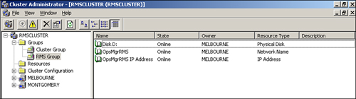
The resources required in a cluster include a cluster resource group, which contains at a minimum the cluster IP address, cluster name, and quorum drive (shown in Figure 10.5). To share resources such as a database or the RMS, you would create a second resource group, which means defining at least one additional IP address, name, and shared drive. Use the Cluster Administrator, available under Start -> All Programs -> Administrative Tools, to create the cluster.

Prior to installing any of the Operations Manager components in a clustered configuration, you must first create the cluster and validate its functionality. You can validate the functionality of the cluster by failing resource groups from one node to the other, testing the functionality, and then failing the resource group back to the original node. Follow these steps:
For our cluster example shown in Figure 10.5, we start with resources running on the Melbourne server (which will host our clustered RMS). To validate the functionality of this cluster, we need to access the shared resources, which in this case are the IP Address, Network Name, and Physical Disk resources. This test involves pinging the name of the cluster (found on the parameters of the cluster name resources) from a system that is not a member of the cluster. A successful ping validates both name resolution and the IP address (found on the parameters of the IP address resource).
To validate the physical disk resource, we access that drive from the node that owns the resource. Opening up the Q: drive on the Melbourne server, you will get one of the following results:
If the node owns the resource, the drive is able to read and write to the drive.
If the node does not own the resource, a message displays stating that the device is not ready.
Once we have validated the resources on the first node, we need to fail over the cluster to the second node. Right-click the resource group and choose the Move Group option. Once you have moved the resources to the other node (see Figure 10.6), perform the same process you performed on the first node. Once that test is done, fail back the resources to the original node.

If there are any failures in these tests, do not continue installing the application you will be clustering (such as the RMS or Microsoft SQL Server). Instead, focus on resolving the issues and stabilizing the cluster before starting the application installation. Do not install a clustered application until the cluster can successfully function on each node of the cluster and can fail over and fail back without issues.
Tip: Installing Clusters in Virtual Server 2005 R2
You can use Microsoft Virtual Server 2005 R2 to provide a clustering environment without the extensive hardware that is typically required. With Virtual Server, you can create a cluster with a single physical node using virtual SCSI controllers to provide the shared storage for the cluster. This is an excellent method to provide both testing or demonstration environments and can also be used in production environments, depending on the hardware requirements.
An excellent write-up that provides step-by-step processes to create a virtual server cluster is available at http://www.roudybob.net/downloads/Setting-Up-A-Windows-Server-2003-Cluster-in-VS2005-Part1.pdf.
Installing a functional cluster is relevant for the OpsMgr components that use SQL Server and for the RMS component, which we will discuss in the “Root Management Server Clustering” section of this chapter.
After installing the cluster, if you will be providing redundancy for an OpsMgr database component, your next step is to install SQL Server 2005 into your clustered configuration. You can use SQL Server 2005 clusters with the Operations Database, Data Warehouse Database, and ACS Database Components. Because installing a SQL Server 2005 cluster is very similar to a nonclustered SQL Server installation, we will focus on what the differences are and what is required to complete the installation:
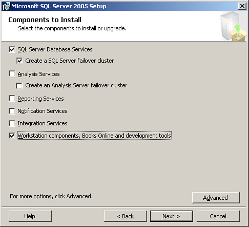
During the database server installation, the major change is the screen that displays what components to install in the process of installing SQL Server 2005 on a cluster. The Components to Install screen has a check box for Create a SQL Server failover cluster, which you need to select. Other items to check include the SQL Server Database Services option and the Workstation components, Books Online and development tools option (see Figure 10.7).
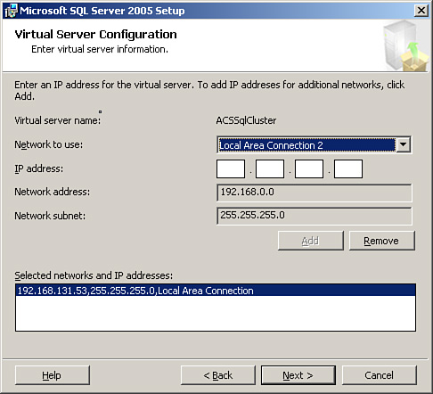
As part of the installation, you also need to configure the Virtual Server IP address (see Figure 10.8). This address specifies the network adapter and IP address used by the SQL Server cluster.
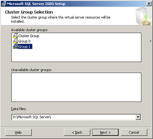
The available cluster groups display in the Cluster Group Selection screen (see Figure 10.9). Choose the cluster group you created to use with SQL Server.
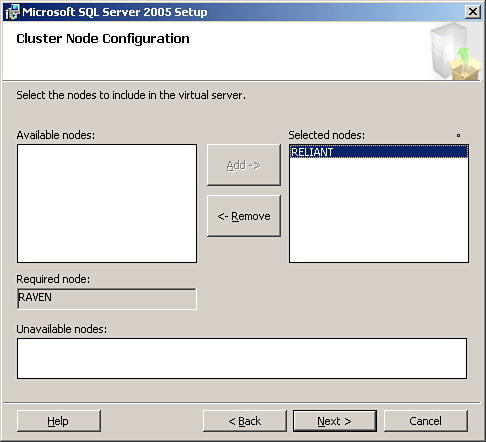
The Cluster Node Configuration screen displays the nodes in the cluster. The available nodes display, with the node you are currently running the installation from is listed in the Required node section, and the other nodes in the cluster are listed in the Available nodes section. Highlight the additional nodes and move them to the Selected nodes section, as we have in Figure 10.10.
There is another cluster-specific screen where you will need to specify the account to use for remote setup. This account will install the SQL Server services on each of the nodes in the cluster you specified.
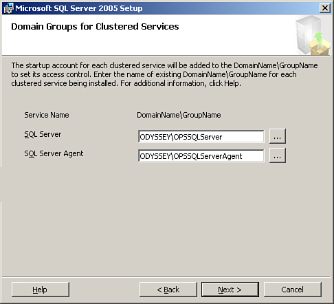
The final cluster-specific screen specifies the startup accounts to use for each clustered service. The installation process does not create these DomainNameGroupName entries, so you should create them before running the setup. Figure 10.11 shows the Domain Groups for Clustered Services screen where you specify the group names.
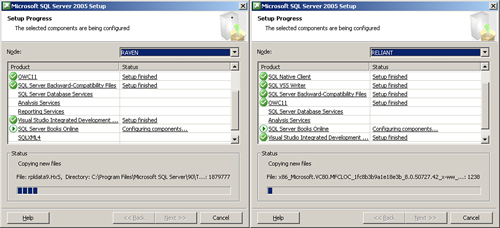
The installation process actually occurs on each of the nodes at the same time (which is actually pretty cool!) and is shown in Figure 10.12.
After the SQL Server 2005 installation completes, install SQL 2005 Service Pack (SP) 1. Run the Service Pack installation in the active node in the cluster; like the SQL 2005 installation, the active node can run both SP 1 installations simultaneously. After installing SP 1, reboot each of the nodes (one at a time) before continuing with any other installation activities on the nodes.
Tip: Startup Mode for the SQL Server Service
Although the SQL Server service must be in automatic startup on nonclustered installations, the service is configured for manual startup in a clustered installation. This is a default configuration on a cluster and is set this way so that it can activate on the node on the cluster that is running SQL Server at that point in time.
Installing the Operations database in a clustered configuration is basically the same as the process explained in Chapter 6. The installation needs to occur on the active node of the SQL cluster. To verify the node, open the Cluster Administrator (Start -> All Programs -> Administrative Tools -> Cluster Administrator), open the connection to the SQL cluster, and make sure that all cluster resources are running on the node where you will be installing the operations database. When installing, make sure to only check the Database component (uncheck the other selections), as shown in Figure 10.13.
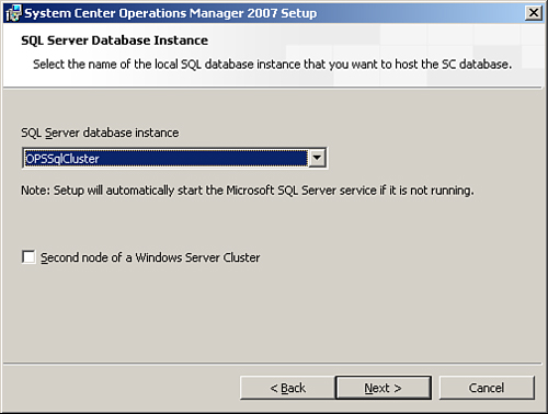
During the installation process, the SQL Server Database Instance screen has a check box labeled Second node of a Windows Server Cluster, as shown in Figure 10.14. This box should not be checked and can be ignored. Because no program files are installed on the cluster nodes during the database-only installation, there is no need to repeat the installation on the second node of the cluster. (We discuss sizing for the database and logs in Chapter 4.)
After completing the installation, you can verify the success of the installation by opening the SQL Server Management Studio (Start -> All Programs -> Microsoft SQL Server 2005 -> SQL Server Management Studio), connecting to the cluster, and verifying that the Operations database exists (the default database name is OperationsManager).
Redundancy Using Log Shipping
Operations Manager 2007 supports log shipping for redundancy on the Operations and Data Warehouse databases.
Log shipping is essentially the process of automating the backup of database and transaction log files on a production SQL server, then restoring them to a standby server. More than that, the key feature of log shipping is that it will automatically back up transaction logs at an interval you specify, and automatically restore them to the standby server. This essentially keeps the two SQL Server systems in sync. If the production server fails (and if you put enough effort into your log shipping setup), all you have to do is point your users to the new server and “go.”
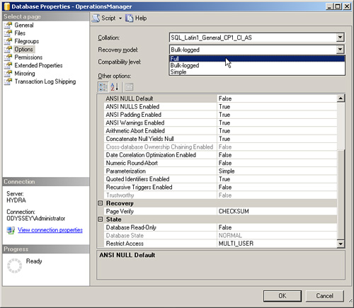
Log shipping requires that the database be set to Full Recovery mode. You can change the recovery mode using the ALTER DATABASE statement with Transact-SQL, or with SQL Server Management Studio. Select Databases -> <database name> and then right-click to select Properties. On the Options page, select the dropdown for Recovery model to change from Simple to Full, as displayed in Figure 10.15 for the OperationsManager database.
Details on how to configure log shipping will be included in the upcoming “Operations Manager 2007 High Availability and Disaster Recovery” white paper, which when it is completed will be available at http://technet.microsoft.com/en-us/opsmgr/bb498235.aspx.
Because the ACS database already has high processing requirements, we do not recommend log shipping (or mirroring) for this database. Also, note that overhead is associated with log shipping, and clustering the Operational and data warehouse databases offers with a less resource-intensive approach.
Before installing the data warehouse, be sure to install and test the cluster (see the “Common Clustering Concepts” section earlier in this chapter) and install SQL 2005 SP 1 on the cluster, as we discuss in the “Installing SQL 2005 Clusters” section.
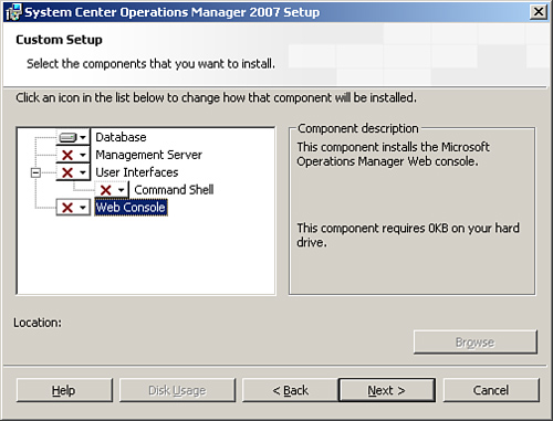
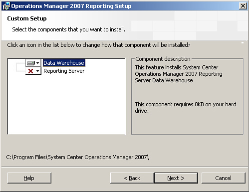
The actual installation process is the same when installing on a cluster as it is when installing on a single system. When you select components in the OpsMgr setup program, be sure to only choose the Data Warehouse Component (see Figure 10.16), and not the Reporting Server Component. The SQL Server Reporting feature is not cluster-aware and we do not recommend you install it on a cluster, because installing both clustered applications and nonclustered applications on a clustered system is not a recommended best practice.
During the setup process, you choose the clustered instance you created when installing the SQL cluster (in the example shown in Figure 10.17, this is the Operations Database instance called OpsSqlCluster).

The database name defaults to OperationsManagerDW and a size of 1GB. Move the database files to shared storage, shown in Figure 10.18, where the data files are on the D: drive and the log files are on the L: drive. This database size should be set to the estimated database size based on the calculations for the data warehouse sizing, discussed in Chapter 4.

Once the database installation is complete, you should see the .mdf and .ldf files in the locations that you specified during the installation (see Figure 10.18 for the path to these files).
The ACS installation will only run from a management server. Therefore, installation prerequisites include installing a management server designated as an ACS collector, and for high availability installing a clustered SQL Server 2005 database environment for the ACS database (see the “Common Clustering Concepts” and “Installing SQL 2005 Clusters” sections for details on these processes). For detailed information on ACS (other than clustering), see Chapter 15, “Monitoring Audit Collection Services.”
Installing the ACS components follows the same steps described in Chapter 6. The ACS installation process installs both the collector and the database. You can validate a successful installation of the database by accessing the server (or cluster) where you created the database and validating that the OperationsManagerAC (default name) exists.
Note: Installing the ACS Components on Separate Servers
Although you can cluster the database, Microsoft does not support clustering the collector. The database typically is installed on the collector. If you want a redundant ACS database, you must install it separate from the collector.
Consider placing the ACS database on a cluster to provide a highly available solution. Each collector reports to its own ACS database server. This means that redundancy is not available for ACS collectors by installing a second ACS collector (unlike management servers or gateway servers, which can have additional servers installed to provide redundancy).
To provide redundancy for the ACS collector, the best available option is installing a second collector that will work as a “cold” server. This cold server is a collector that is installed and configured to report to the ACS database server but has the ACS service (the Operations Manager Audit Collector service) disabled on the system. For our environment, the first ACS collector installed is Hurricane, and the cold backup ACS server is Hopi (as we illustrated in Figure 10.4 earlier in the chapter). Another option to provide redundancy is to install multiple pairs of ACS collectors/database servers. We discuss this approach in Chapter 15.
Installing the OpsMgr Data Warehouse or Operations database only creates the database on the specified server; the installation process does not install any executable programs on the server. This is important because it increases the likelihood that these database components will be able to coexist on the same server without having issues from interaction. The ACS installation actually runs from the collector (not from the ACS database server), implying that it also does not install binary files as part of its installation process. This is important because it greatly increases the likelihood that these databases can coexist with other databases on the same server or cluster.
We have deployed multiple configurations where the Operations and Data Warehouse databases run on the same physical node and although there is an impact in terms of increased CPU, memory, disk, and network load, we have not seen any collisions caused by these databases running on the same physical server in the same SQL instance. These concepts bring two major variations on the supported cluster configurations, which would be very likely configurations to use in production deployments. Please note that Microsoft does not support either of the following two configurations at this time, but they should be viable configurations based on available information:
The first configuration installs all three databases on a single server into a single SQL Server instance. The result would be one instance with the OperationsManager, OperationsManagerDW, and OperationsManagerAC databases (remember these are all default names which can be changed) in that instance. This option is now supported but not recommended by Microsoft.
Providing each of these three functions from a single server will require a more powerful hardware configuration than if these run on three separate servers. The actual configuration you would use would vary depending on the number of agents you will be monitoring and the management packs that are deployed. Best-practice approaches to this would be a configuration with high-end equipment that includes the following:
At least four processors
Sixteen gigabytes of memory
A gigabit network adapter
Dedicated drives for each of the log and database files, separated for each of the three databases
A second logical configuration to draw from this is a four-node cluster in an Active/Active/Active/Passive configuration:
The first node would host the Operations database in the default cluster instance.
The second node would host the Data Warehouse database in a second instance.
The third node would host the ACS database in a third instance.
The fourth node would be available to provide high availability in case of the failure of a node in the cluster.
OpsMgr’s capability to capture, aggregate, and report on application crashes depends on the availability of the Agentless Exception Monitoring share. A Group Policy Administrative template specifies the location of this share to the ACS clients. If the AEM share is not available, crash data is not reported.
There are currently no supported (or recommended) methods to provide high availability for the AEM file share. However, using either the Windows 2003 Distributed File System (DFS) or Windows Clustering may provide a viable method of making this share available, even if one of the nodes hosting the sharing is unavailable. At this time, there are several issues with the DFS approach:
The Client Monitoring Configuration Wizard does not allow using a DFS share, because the wizard itself creates the share rather than using an existing file share.
Using DFS to provide redundancy may result in large amount of additional network traffic as the different DFS servers communicate crash information between them.
Windows Vista clients communicate via port number 51906, so this form of high availability will not work for Vista clients, because they communicate via the port, not the share.
Clustering the server that provides the file share functionality (and running it on the RMS) may be the most viable option in the future. This method would allow both the share functionality and port 51906 functionality while providing a highly available solution.
Installing a reporting server within a highly available environment follows the same process used for new installations (which we discussed in Chapter 6).
Tip: SQL Reporting and Other OpsMgr Databases
Microsoft does not recommend installing the SQL Reporting components on a database server already providing OpsMgr functionality (such as the Operations, Data Warehouse, and ACS databases). SQL Reporting is an intensive application, and it may cause performance issues when installed on a server that is providing a role other than the SQL Server Reporting function.
However, this concern must be balanced with the reality that creating a separate SQL Reporting environment is generally overkill, especially when considering that the SQL reporting environment cannot be shared with other SQL reports due to the new security model implemented with the Operations Manager 2007 Reporting component.
We have not seen issues with these components coexisting as long as the hardware acquired for the database and reporting server is sufficient.
Note the following items of interest when installing the reporting components:
When installing the prerequisites for the reporting components, remember to install IIS and ASP.NET before installing the SQL Server 2005 components (otherwise, the reporting services option is not available when you install the SQL Server components).
During the OpsMgr installation process, specify a custom installation and only choose the Reporting Server option (see Figure 10.19).
During the installation, there is a step where you need to enter the name of the RMS. For a highly available configuration, you need to specify the name of the RMS cluster. Figure 10.20 shows an example, where we use a RMS cluster name of OpsMgrRms.
You will need to specify the name of the SQL Server Database instance (in our example, DWSQLCluster), the SQL database name (defaults to OperationsManagerDW) and the port (1433 by default), as shown in Figure 10.21. If you have multiple instances installed on the SQL Server, you will need to specify the SQL instance and the port associated with the instance on this screen.


When the installation completes successfully, we have a functional OpsMgr Reporting server on a single server. At this point, we have a supported configuration, but we do not have a highly available solution.
As we discuss in Chapter 4, you can establish redundancy for this component by using Network Load Balancing, although Microsoft does not support this. The trick on this is how to keep the reporting information in sync between the systems.
Our tests indicate that the first step in creating a redundant reporting configuration is installing a single Reporting server with the Data Warehouse Components on a different server (or cluster, as discussed in the “Operations Database Clustering” and “Data Warehouse Clustering” sections of this chapter). This installation places the report databases local to the system where we installed the OpsMgr reporting components.
To make the configuration redundant, manually replicate the reporting databases between the two systems, and then configure NLB on both reporting servers. Finally, change the OpsMgr configuration to use the NLB address instead of the address of the originally installed reporting server. You can change the address in the Operations console at Administration -> Settings -> Reporting.
We recommend this approach as the most likely method of providing redundancy for the Reporting Server Component at this time.
The RMS is the only management server in the management group running the OpsMgr SDK and OpsMgr Config services. Clustering these services (and the RMS) can provide high availability. Installing a clustered RMS is not a simple process, because the RMS installs as a generic application using generic services.
As an example, when you installed the SQL cluster earlier in this chapter (in the “Installing SQL Server 2005 Clusters” section), the installation created the resources (such as the services) and placed them into the resource group. This is not the case for the RMS cluster. Additional steps are required during the installation process, which are not required with a more cluster-aware application such as SQL Server or Exchange.
The process to install a clustered RMS is not a short one. We recommend testing this process through a virtual configuration prior to trying it in a production environment because this is a long and complicated process.
The following are the high-level steps we will use to install the RMS Cluster.
Validate cluster prerequisites—Install the cluster and verify it is fully functional, as discussed in the “Common Clustering Concepts” section of this chapter.
Group and resources—Create the RMS resource group and resources (IP Address, Physical Disk, Network Name).
OpsMgr prerequisites—Install the prerequisites on each node for the OpsMgr management server and user interface.
OpsMgr security—Verify that the Operations Manager Administrators group is part of the local Administrators security group and that the Cluster service account is a member of the domain Operations Manager Administrators security group. Add the SDK and Config service accounts in the Local Administrators group on each node.
RMS and MS installations—Perform an installation of only the management server and console options first on the primary node of the cluster and then on the secondary nodes of the cluster.
RMS cluster resources—Create resources for the three Windows services (Health, Config, and SDK services).
Sharing the RMS key—Create a file share and export the RMS key.
Creating the Virtual RMS—Use the ManagementServerConfigTool to create the Virtual RMS cluster and add nodes to the cluster.
Testing the cluster—Validate that the cluster works through the Operations console.
To create the RMS resource group and resources, perform the following steps:
Log on to the primary node of the cluster with full administrative rights. We will refer to the first node in the cluster as the primary node of the cluster, and additional nodes of the cluster as secondary nodes.
Open the Cluster Administrator (Start -> All Programs -> Administrative Tools). Create a cluster group for the RMS called RMS Group.
Within the cluster group, we will create resources for the IP address, physical disk, and network name, as shown in Figure 10.22.
For each of the resources created, the possible owners should be all nodes in the cluster.
Within the RMS group, create an IP Address resource. The configuration for this resource should be as follows:
Possible owners—All nodes in the cluster.
Resource dependencies—None.
Parameters—Publicly accessible IP address and subnet mask. Select the public network from the Network dropdown list.
Within the RMS group, create a Physical Disk resource. The configuration for this resource should be as follows:
Possible owners—All nodes in the cluster.
Resource dependencies—None.
Parameters—A drive letter to the dedicated RMS disk must already exist and be available to all the nodes in the cluster.
Within the RMS group, create a network name resource. The configuration for this resource should be as follows:
Possible owners—All nodes in the cluster.
Resource dependencies—The RMS IP address resource.
Parameters—A valid NetBIOS name in the Name field. Do not select the DNS Registration Must Succeed check box. Do select the Enable Kerberos Authentication check box, as shown in Figure 10.23.
Right-click the RMS cluster group and click Bring Online. If the group does not come online successfully, a likely cause is a previous association of the IP address or network name either in DNS or Active Directory.

On each node of the cluster, check the prerequisites for installing the management server and user interface components, using the Check Prerequisites option from the SetupOM program on the OpsMgr installation media. These prerequisites should include Windows Server 2003 SP 1, MDAC version 2.80.1022.0 or later, .NET Framework version 2.0, and .NET Framework version 3.0 components.
You can ignore warnings from the prerequisite checker, but there is a risk of degraded performance, as shown with the example in Figure 10.24, where the system does not have enough memory available to run the RMS functionality efficiently. You must fix any failed prerequisites prior to installing the OpsMgr components.

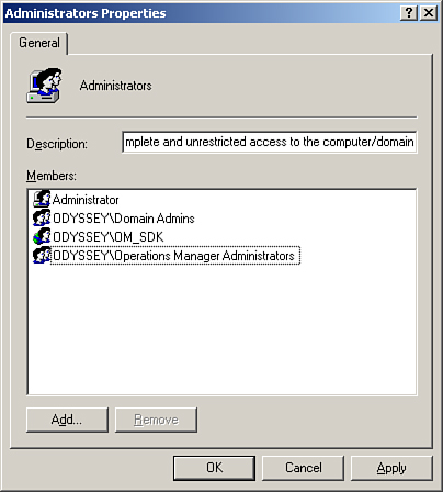
For each node in the RMS cluster, add the domain Operations Manager Administrators security group into the local Administrators group (if this global group does not already exist, create a group with this name as a global security group in the domain). The cluster service account needs to be a member of the Operations Manager Administrators security group that you previously added to the local Administrators group on each node. Also, add the SDK and Config service account (OM_SDK, in our case) to the local Administrators group on each node (see Figure 10.25).
Installing the RMS on a cluster is the same process used when installing a nonclustered RMS (see Chapter 6 for details). As a reminder, choose a custom installation, selecting only the Server and Console options during the installation.
For the remaining nodes in the cluster, perform the same installation process for the RMS installation again, using a custom installation and only selecting the Server and Console options.
Now that we have the RMS and Management Server Components installed, log back in to the primary node of the cluster (using an account with full administrative rights). Open the Cluster Administrator. Within the RMS Group, we will be creating new services. Right-click the RMS Group and select New -> Resource. Using the New Resource Wizard, create a service with the following configuration:
Name—RMS Health Service.
Resource type—Generic Service.
Group—RMS Group.
Possible owners—All nodes in the cluster.
Resource dependencies—The RMS Disk and RMS Network Name resources, which we previously defined in the “Group and Resources” section of this chapter.
Generic Service Parameters—In the Service name field, enter HealthService (this must be exact and cannot be modified).
Startup Parameters—Leave this blank.
Registry Replication—Leave this blank.
Perform a similar process for the Operations Manager Config Service:
Name—RMS Config Service.
Resource type—Generic Service.
Group—RMS Group.
Possible owners—All nodes in the cluster.
Resource dependencies—The RMS Disk and RMS Network Name resources, which we defined in the “Group and Resources” section of this chapter.
Generic Service Parameters—On the Service name field, enter OMCFG (this must be exact and cannot be modified).
Startup Parameters—Leave this blank.
Registry Replication—Leave this blank.
Perform the same process for the Operations Manager SDK Service:
Name—RMS SDK Service.
Resource type—Generic Service.
Group—RMS Group.
Possible owners—All nodes in the cluster.
Resource dependencies—The RMS Disk and RMS Network Name resources, which we defined in the “Group and Resources” section of this chapter.
Generic Service Parameters—On the Service name field, enter OMSDK (this must be exact and cannot be modified).
Startup Parameters—Leave this blank.
Registry Replication—Leave this blank.
To share the RMS key, we will create a file share on the network accessible from all cluster nodes and name it RMSKey. This share will provide a location for storing the RMS key. Give the account running the Cluster service full access to the file share. For security purposes, you may want to make this a hidden share—append a dollar sign ($) to the end of the share name to hide the share. Perform the following steps:
Log in to the primary cluster node with the account the Cluster service is running under. Move the cluster resources to the primary node of the cluster if they are not already there.
From the Operations Manager 2007 installation media, copy the SecureStorageBackup.exe and ManagementServerConfigTool.exe files from the SupportTools folder to the installation folder for OpsMgr (by default %ProgramFiles%System Center Operations Manager 2007).
Open a command prompt and
cdto the folder where you copied the files. From the command prompt, we will make a backup of the RMS key with the following syntax:<LINELENGTH>90</LINELENGTH>SecureStorageBackup.exe Backup \<ServerName><ShareName>RMSkey.bin
For instance, the command
SecureStorageBackup.exe Backup \PantheonRMSKEYRMSkey.binwould back up the key to the Pantheon server in the RMSKEY share.When you enter the
SecureStorageBackupcommand, you must enter and confirm a password that is at least eight characters long and includes at least one symbol. Make note of this password, because it will be required not only for the process of installing the RMS cluster but also in a disaster recovery scenario.Next, we need to restore the RMSKEY onto each secondary node. To do this, log in to each secondary node and copy the SecureStorageBackup file to the installation directory for the system.
Open a command prompt and
cdto the folder where you copied the files. From the command prompt, we will restore the backup of the RMS key with the following syntax:<LINELENGTH>90</LINELENGTH>SecureStorageBackup.exe Restore \<ServerName><ShareName>RMSkey.bin
As an example,
SecureStorageBackup.exe Restore \PantheonRMSKEYRMSkey.binrestores the key stored on the Pantheon server within the RMSKEY share. You will be required to enter the same password you created when you exported the RMS key from the primary node.
You have now restored the RMS key to each node of the cluster.
Caution: Back Up the Operations Database
Before actually creating the RMS cluster, perform a full backup the Operations database. For details on how to backup the database, see Chapter 12, “Backup and Recovery.”
In the next step of this process, we will use the ManagementServerConfigTool to create the RMS cluster. Because this tool can potentially cause irrecoverable damage to the database, a backup is strongly suggested prior to continuing.
To create the virtual RMS, log back in to the primary node of the cluster and perform the following steps:
Open a command prompt and
cdto the Operations Manager installation directory.Use the ManagementServerConfigTool.exe tool to instantiate the RMS cluster group as a cluster, as follows:
<LINELENGTH>90</LINELENGTH>ManagementServerConfigTool.exe InstallCluster /vs:<VirtualServerNetBiosName> /Disk:<RMS Disk resource letter>
Figure 10.26 shows an example of using the ManagementServerConfigTool with the virtual server name of OpsMgrRms on the D: drive.
Caution: Using the
SetSPNCommandRun the ManagementServerConfigTool utility using the account that is running the cluster service. If you run this under a different account, you will need to run the SetSPN utility manually.
Details on the process to create the SPN manually are included within the Operations Manager 2007 Deployment Guide, available for download at http://technet.microsoft.com/en-us/opsmgr/bb498235.aspx. SetSPN itself is available in the Windows 2000 Resource Kit at http://go.microsoft.com/fwlink/?LinkId=80094.
After the primary node has run the ManagementServerConfigTool and it has successfully completed, perform the same process on the secondary nodes as well. Log in to the secondary node, and within the cluster administrator move the RMS cluster resources to the node you are logged in to.
As an example, if the primary node is Montgomery and the secondary node is Melbourne, we would now log in to the Melbourne server and move any cluster resources over from Montgomery onto Melbourne.
From the Windows Services management console, change the startup type for the OpsMgr SDK service from Disabled (the default when not the RMS) to Automatic. Then start the OpsMgr SDK service. Note that the OpsMgr SDK service must be running on the primary RMS node as well.
Note: Initial Startup Type for the OpsMgr SDK Service on Secondary Cluster Node
Although one might think that the service would already have its startup type set as Manual because the cluster is controlling the service, this is not the case. The first node in the cluster has the service set to Automatic because it has the RMS role. The second node initially has the startup type as Disabled; we change it to Manual here as part of establishing our RMS cluster.
Open a command prompt to the Operations Manager installation directory and run the ManagementServerConfigTool with a configuration that adds the node to the cluster:
<LINELENGTH>90</LINELENGTH>ManagementServerConfigTool.exe AddRMSNode /vs:<VirtualServerNetBiosName> /Disk:<RMS Disk resource letter>
For the Montgomery/Melbourne example, the shared disk is D: and the VirtualServerNetBiosName is OpsMgr RMS. The sample syntax for this on the secondary node (Melbourne) would be the following:
<LINELENGTH>90</LINELENGTH>ManagementServerConfigTool.exe AddRMSNode /vs:OpsMgrRms /Disk:D

To test the functionality of your OpsMgr RMS cluster, open the Operations console. To log in, you will need to specify the name of the RMS cluster (in our example, it is OpsMgrRms) for the server name. In the console, navigate to Administration -> Device Management -> Management Server. You should now see the name of the RMS cluster listed as a management server. In addition, under Administration -> Device Management -> Agentless Managed, you should also see the names of the nodes in the cluster as in Figure 10.27. Notice that the cluster nodes appear as agentless managed. This should change once the Clustering management pack is available, but for now it is normal.

You can also use the ldifde utility to verify everything is registered properly in Active Directory. Syntax would be the following:
Ldifde -f c:ldifdeout.txt -t 3268 -d DC=<domain name>,DC=COM -l serviceprincipalname -p subtreeAlthough the majority of the entries will register automatically during your OpsMgr installation, you may need to use SetSPN to register the virtual name of the RMS cluster. If you are registering manually, register both the NetBIOS name itself and the FQDN.
The following are SPN entries for a properly registered virtual RMS:
dn: CN=CLUST-RMS,CN=Computers,DC=ODYSSEY,DC=com
changetype: add
servicePrincipalName: MSOMHSvc/OPSMGRRMS
servicePrincipalName: MSOMHSvc/OPSMGRRMS.ODYSSEY.com
servicePrincipalName: MSOMHSvc/MONTGOMERY
servicePrincipalName: MSOMHSvc/MONTGOMERY.ODYSSEY.com
servicePrincipalName: MSOMHSvc/MELBOURNE
servicePrincipalName: MSOMHSvc/MELBOURNE.ODYSSEY.com
servicePrincipalName: MSClusterVirtualServer/OPSMGRRMS
servicePrincipalName: MSClusterVirtualServer/OPSMGRRMS.ODYSSEY.com
servicePrincipalName: HOST/OPSMGRRMS
servicePrincipalName: HOST/OPSMGRRMS.ODYSSEY.com
Here are some points to note:
OPSMGRRMS is the virtual name of the RMS cluster.
ODYSSEY is the domain name.
MONTGOMERY and MELBOURNE are the two physical nodes in the RMS cluster.
Note that if the server is in a child domain, you will need DC entries for each level in ldifde. We have also found the following caveats:
AD does not validate the service name. Be sure you type correctly!
SetSPN does not return any sort of “access denied” errors if you run it with insufficient privileges.
When creating an Operations Manager 2007 environment, you have four primary areas to consider in providing an optimally performing configuration: memory, disk, processor, and network performance. We complete this chapter by discussing each of these aspects in the following sections.
The amount of memory available to the servers in an Operations Manager 2007 environment has the most direct impact on the performance of OpsMgr. There are a variety of reasons why this is the situation:
SQL Server 2005 really likes memory. With its default configuration, SQL Server will use as much memory as it can. We have worked in environments with fewer than 200 servers and the combined Operations and Data Warehouse SQL Server database engine was using more than 11GB on a 16GB server. In another environment we worked in, the Operations database server had a total of 4GB of memory, and all 4GB of memory were consistently in use either by SQL Server or by the Operating System.
The RMS really likes memory. We have seen implementations with fewer than 200 agents where the RMS had 8GB of memory and consistently used more than 5GB. In another environment where there were fewer than 300 agents and the RMS had 6GB of memory, it consistently used over 4GB of memory. We used the Task Manager to gather the memory statistics discussed here on the Performance tab from Pagefile Usage. These memory statistics do not consider how much memory the System Cache was using, so the actual memory in use on the server was even higher.
The System Cache is one of the most underestimated performance boosts available within Windows. The System Cache takes memory and uses it to store data that was accessed from the drive, and stores it in memory. While working on one client engagement, by dedicating large amounts of memory for System Cache, we were able to achieve a 500% application performance increase by using the System Cache functionality.
The current amount of memory used by the System Cache is viewable through the Task Manager. To determine how much memory you are using for the System Cache, select the Performance tab within the Task Manager. The System Cache displays within the Physical Memory section of the Task Manager, as shown in Figure 10.28. This is a server running the RMS (Windows 64-bit) with 6GB of memory installed (4.57GB in use plus just over 1GB of System Cache in use). For Operations Manager 2007, the System Cache provides benefits to the RMS by caching frequently accessed files such as those used by the OpsMgr programs that run. A great discussion on how this works is available at http://channel9.msdn.com/ShowPost.aspx?PostID=61242.

To summarize our recommendations on memory: Go big! Particularly with 64-bit operating systems, the cost required to install systems using over 2GB of memory is not anywhere near where it was in recent years. For the RMS, go with 8GB if the cost is not prohibitive. For database servers, go with 16GB (or 32GB if that is not cost prohibitive). The more memory, the better the performance you will have with your Operations Manager environment.
Operations Manager itself will notify you when you are reaching bottlenecks with your servers that run your Operations Manager components. During one deployment, we started with an RMS on a server that had 2GB of memory, but due to messages from OpsMgr, we ended up increasing it to 6GB. On the database side, we started with a 4GB configuration but ended up upgrading it to an 8GB configuration (again due to bottlenecks identified by OpsMgr itself).
Disk performance is extremely important, particularly for the database-related components used by Operations Manager. From a disk perspective, the more spindles the SQL Server has, the better it will perform. The preferred method is to configure your system using multiple drives for the operating system, SQL binaries, and the Windows page file (swap file), transaction logs, and data files:
The exception to this rule is when you are connecting your SQL Server to a Storage Array Network (SAN). In this situation, you would use the following configuration:
Use RAID 1 for the operating system drive (locally stored), or boot to the SAN.
Use RAID 1 or RAID 5 for SQL binaries and the swap file because they are always read from (locally stored), or store the data on the SAN.
Use the SAN to store the log files on one Logical Unit Number (LUN). The personnel responsible for configuring the SAN can best determine the actual RAID configuration for the LUN.
Use the SAN to store the database files on another LUN.
Remember that when it comes to performance, the more spindles you can put to a drive, the better the performance you will get from it. As an example, a RAID 10 array with four drives outperforms a RAID 10 array with two drives!
Although processor performance is important in Operations Manager, OpsMgr bottlenecks are most likely from memory or disk from a performance perspective. The same applies from a networking perspective. For high-usage environments, consider a gigabit network connection for the various OpsMgr servers to communicate with each other; but a bottleneck on the network adapter is not very likely from what we have seen.
In this chapter, we have discussed some of the more complex configurations that can exist within an Operations Manager 2007 environment. These include multihomed configurations, connected management groups, gateway servers, redundant configurations, and performance considerations. The next chapter discusses securing Operations Manager 2007.